Intel DG33TL Product Specification - Page 23
Parallel IDE Controller, Real-Time Clock Subsystem - ram
 |
View all Intel DG33TL manuals
Add to My Manuals
Save this manual to your list of manuals |
Page 23 highlights
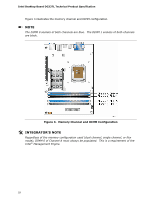
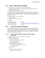
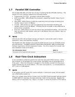
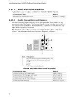
Product Description 1.7 Parallel IDE Controller The Parallel ATA IDE controller has one bus-mastering Parallel ATA IDE interface. The Parallel ATA IDE interface supports the following modes: • Programmed I/O (PIO): processor controls data transfer. • 8237-style DMA: DMA offloads the processor, supporting transfer rates of up to 16 MB/sec. • Ultra DMA: DMA protocol on IDE bus supporting host and target throttling and transfer rates of up to 33 MB/sec. • ATA-66: DMA protocol on IDE bus supporting host and target throttling and transfer rates of up to 66 MB/sec. ATA-66 protocol is similar to Ultra DMA and is device driver compatible. • ATA-100: DMA protocol on IDE bus allows host and target throttling. The ATA-100 logic can achieve read transfer rates up to 100 MB/sec and write transfer rates up to 88 MB/sec. NOTE ATA-66 and ATA-100 are faster timings and require a specialized cable to reduce reflections, noise, and inductive coupling. The Parallel ATA IDE interface also supports ATAPI devices (such as CD-ROM drives) and ATA devices. The BIOS supports Logical Block Addressing (LBA) and Extended Cylinder Head Sector (ECHS) translation modes. The drive reports the transfer rate and translation mode to the BIOS. For information about The location of the Parallel ATA IDE connector Refer to Figure 10, page 44 1.8 Real-Time Clock Subsystem A coin-cell battery (CR2032) powers the real-time clock and CMOS memory. When the computer is not plugged into a wall socket, the battery has an estimated life of three years. When the computer is plugged in, the standby current from the power supply extends the life of the battery. The clock is accurate to ± 13 minutes/year at 25 ºC with 3.3 VSB applied. NOTE If the battery and AC power fail, custom defaults, if previously saved, will be loaded into CMOS RAM at power-on. When the voltage drops below a certain level, the BIOS Setup program settings stored in CMOS RAM (for example, the date and time) might not be accurate. Replace the battery with an equivalent one. Figure 1 on page 12 shows the location of the battery. 23
-
 1
1 -
2
-
3
-
4
-
5
-
6
-
7
-
8
-
9
-
10
-
11
-
12
-
13
-
14
-
15
-
16
-
17
-
 18
18 -
 19
19 -
 20
20 -
 21
21 -
 22
22 -
 23
23 -
 24
24 -
 25
25 -
 26
26 -
 27
27 -
 28
28 -
29
-
30
-
31
-
32
-
33
-
34
-
35
-
36
-
37
-
38
-
39
-
40
-
41
-
42
-
43
-
44
-
45
-
46
-
47
-
48
-
49
-
50
-
51
-
52
-
53
-
54
-
55
-
56
-
57
-
58
-
59
-
60
-
61
-
62
-
63
-
64
-
65
-
66
-
67
-
68
-
69
-
70
-
71
-
72
-
73
-
74
-
75
-
76
-
77
-
78
-
79
-
80
-
81
-
82
-
83
-
84
-
85
-
86
-
87
-
88
 |
 |