Intel DG33TL Product Specification - Page 35
Fan Headers, 13.2.3, LAN Wake Capabilities, CAUTION - cpu fan
 |
View all Intel DG33TL manuals
Add to My Manuals
Save this manual to your list of manuals |
Page 35 highlights
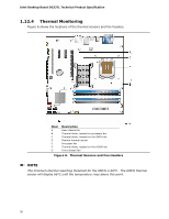
Product Description 1.13.2.2 Fan Headers The function/operation of the fan headers is as follows: • The fans are on when the board is in the S0 state. • The fans are off when the board is off or in the S3, S4, or S5 state. • The CPU fan header is wired to a fan tachometer input and the Front and Rear fan headers share the tachometer input of the hardware monitoring and fan control device. All fan headers support closed-loop fan control that can adjust the fan speed or switch the fan on or off as needed. • All fan headers have a +12 V DC connection. For information about The locations of the fan headers and thermal sensors The signal names of the processor fan header The signal names of the chassis fan headers Refer to Figure 6, page 30 Table 18, page 47 Table 17, page 47 1.13.2.3 LAN Wake Capabilities CAUTION For LAN wake capabilities, the +5 V standby line from the power supply must be capable of providing adequate +5 V standby current. Failure to provide adequate standby current when implementing LAN wake capabilities can damage the power supply. LAN wake capabilities enable remote wake-up of the computer through a network. The LAN subsystem PCI bus network adapter monitors network traffic at the Media Independent Interface. Upon detecting a Magic Packet* frame, the LAN subsystem asserts a wake-up signal that powers up the computer. Depending on the LAN implementation, the board supports LAN wake capabilities with ACPI in the following ways: • The PCI Express WAKE# signal • The PCI bus PME# signal for PCI 2.3 compliant LAN designs ⎯ By Ping ⎯ Magic Packet • The onboard LAN subsystem • Wake from CIR 35
-
 1
1 -
2
-
3
-
4
-
5
-
6
-
7
-
8
-
9
-
10
-
11
-
12
-
13
-
14
-
15
-
16
-
17
-
18
-
19
-
20
-
21
-
22
-
23
-
24
-
25
-
26
-
27
-
28
-
29
-
 30
30 -
 31
31 -
 32
32 -
 33
33 -
 34
34 -
 35
35 -
 36
36 -
 37
37 -
 38
38 -
 39
39 -
 40
40 -
41
-
42
-
43
-
44
-
45
-
46
-
47
-
48
-
49
-
50
-
51
-
52
-
53
-
54
-
55
-
56
-
57
-
58
-
59
-
60
-
61
-
62
-
63
-
64
-
65
-
66
-
67
-
68
-
69
-
70
-
71
-
72
-
73
-
74
-
75
-
76
-
77
-
78
-
79
-
80
-
81
-
82
-
83
-
84
-
85
-
86
-
87
-
88
 |
 |