Intel DG41MJ Product Guide
Intel DG41MJ - Desktop Board Classic Series Motherboard Manual
 |
UPC - 735858206907
View all Intel DG41MJ manuals
Add to My Manuals
Save this manual to your list of manuals |
Intel DG41MJ manual content summary:
- Intel DG41MJ | Product Guide - Page 1
Intel® Desktop Board DG41MJ Product Guide Order Number: E59138-001 - Intel DG41MJ | Product Guide - Page 2
Intel® Desktop Board DG41MJ Product Guide Date February 2009 If an FCC declaration of conformity marking is present on the board instructions INTEL® PRODUCTS. NO LICENSE, EXPRESS Intel may make changes to specifications and product descriptions at any time, without notice. Intel® Desktop Board DG41MJ - Intel DG41MJ | Product Guide - Page 3
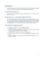
by Intel. Document Organization The chapters in this Product Guide are arranged as follows: 1 Desktop Board Features: a summary of product features 2 Installing and Replacing Desktop Board Components: instructions on how to install the Desktop Board and other hardware components 3 Updating the BIOS - Intel DG41MJ | Product Guide - Page 4
Intel Desktop Board DG41MJ Product Guide Conventions The following conventions are used in this manual: CAUTION Cautions warn the user about how to prevent damage to hardware or loss of data. NOTE Notes call attention to important information. Terminology The - Intel DG41MJ | Product Guide - Page 5
1 Desktop Board Features Desktop Board Components 11 Processor ...12 Main Memory...13 Intel® G41 Express Chipset 14 Graphics Support 14 Intel® GMA X4500 Graphics Controller 14 DVI Support 14 Audio Subsystem 15 Legacy Input/Output (I/O) Controller 15 LAN Subsystem 16 USB 2.0 Support 17 - Intel DG41MJ | Product Guide - Page 6
Intel Desktop Board DG41MJ Product Guide Connecting the Processor Fan Heat Sink Cable 31 Removing the Processor 31 Installing and Removing Memory 32 Installing DIMMs 33 Removing DIMMs 35 Using the Serial ATA (SATA) Cables 35 Connecting a Standard SATA Drive 36 Connecting a Slimline SATA Drive - Intel DG41MJ | Product Guide - Page 7
43 21. Connecting Power Supply Cables 44 22. Location of the BIOS Configuration Jumper Block 45 23. Removing the Battery 51 Tables 1. Feature Summary 9 2. Intel Desktop Board DG41MJ Components 12 3. Audio Jack Retasking Support 15 4. LAN Connector LEDs 16 5. Front Panel Audio Signal Names for - Intel DG41MJ | Product Guide - Page 8
Intel Desktop Board DG41MJ Product Guide viii - Intel DG41MJ | Product Guide - Page 9
for an Intel® processor in the LGA775 package • Two 240-pin, DDR2 SDRAM Dual Inline Memory Module (DIMM) sockets • 800/667 MHz single or dual channel DDR2 SDRAM interface • Support for up to 8 GB of system memory Intel® G41 Express Chipset consisting of: • Intel G41 Express Chipset Graphics and - Intel DG41MJ | Product Guide - Page 10
Desktop Board DG41MJ Product Guide Table 1. Feature Summary (continued) BIOS • Intel® Platform Innovation Framework for extensible firmware interface • 8 Mb symmetrical flash memory device • Support for SMBIOS • Intel® Rapid BIOS Boot • Intel® Express BIOS Update Power Management • Support - Intel DG41MJ | Product Guide - Page 11
Desktop Board Features Desktop Board Components Figure 1 shows the approximate location of the major components on Intel Desktop Board DG41MJ. Figure 1. Intel Desktop Board DG41MJ Components 11 - Intel DG41MJ | Product Guide - Page 12
function properly. Intel Desktop Board DG41MJ supports an Intel processor in the LGA775 package. Processors are not included with the Desktop Board and must be purchased separately. The processor connects to the Desktop Board through the LGA775 socket (Figure 1, G). For instructions on installing - Intel DG41MJ | Product Guide - Page 13
Desktop Board Features Main Memory NOTE To be fully compliant with all applicable Intel ® SDRAM memory specifications, the board should be populated with DIMMs that support the Serial Presence Detect (SPD) data structure. If your memory modules do not support SPD, you will see a notification to this - Intel DG41MJ | Product Guide - Page 14
to the processor, memory, PCI, and the DMI interconnect. The component also provides integrated graphics capabilities supporting 3D, 2D, and display capabilities. ICH7 is a centralized controller for the board's I/O paths. Graphics Support The Intel G41 Express Chipset supports two separate - Intel DG41MJ | Product Guide - Page 15
Desktop Board Features Audio Subsystem The onboard audio subsystem consists of the following: • Intel® ICH7 • Realtek ALC888VC audio codec • Back panel audio connectors (see Figure 19) • Front panel audio header supporting both Intel High Definition Audio and AC '97 Audio (see Figure 18, A) The - Intel DG41MJ | Product Guide - Page 16
Intel Desktop Board DG41MJ Product Guide LAN Subsystem The LAN subsystem includes: • Intel ICH7 • Realtek 8111D-GR Gigabit Ethernet Controller for operation at 10/100/1000 Mb/s • RJ-45 LAN connector with integrated status LEDs The subsystem features: • - Intel DG41MJ | Product Guide - Page 17
operating systems that do not support USB 2.0. Serial ATA The Desktop Board supports three Serial ATA channels (3.0 Gb/s) via ICH7, connecting one device per channel. Expandability For system expansion, the Desktop Board includes one PCI bus connector. BIOS The BIOS provides the Power-On Self - Intel DG41MJ | Product Guide - Page 18
password to boot the computer. For instructions on resetting the password, see Clearing Passwords on page 46. Hardware Management Features The hardware management features of Intel Desktop Board DG41MJ enable the board to be compatible with the Wired for Management (WfM) specification. The board has - Intel DG41MJ | Product Guide - Page 19
technology (Suspend to RAM) ⎯ +5 V standby power indicator LED ⎯ Wake from USB ⎯ Power Management Event signal (PME#) wake-up support ⎯ Wake from PS using the Last Power State feature in the BIOS Setup program's Boot menu. The Desktop Board has two power connectors. See Figure 21 on page 44 - Intel DG41MJ | Product Guide - Page 20
Intel Desktop Board DG41MJ Product Guide Fan Headers The function/operation of the fans is as follows: • The fans are on when the computer is in the ACPI S0 state. • The fans are off when the computer is in the ACPI S3, S4, or S5 state. • The processor fan header is wired to a fan tachometer input. - Intel DG41MJ | Product Guide - Page 21
present at the memory module sockets and the PCI bus connector. Figure 3. Location of the Standby Power Indicator For more information on standby current requirements for the Desktop Board, refer to the Technical Product Specification at http://www.intel.com/products/motherboard/DG41MJ/index.htm. 21 - Intel DG41MJ | Product Guide - Page 22
Intel Desktop Board DG41MJ Product Guide Wake from USB Support NOTE Wake from USB requires the use of a USB peripheral that supports Wake from USB. USB bus activity wakes the computer from an ACPI S1 or S3 state. PME# Signal Wake-up Support When the PME# signal on the PCI bus is asserted, the - Intel DG41MJ | Product Guide - Page 23
• Install the I/O shield • Install and remove the Desktop Board • Install and remove a processor • Install and remove memory • Use the Serial ATA cables • Connect to the from its power source and from any telecommunications links, networks, or modems before performing any of the procedures described - Intel DG41MJ | Product Guide - Page 24
Intel Desktop Board DG41MJ Product Guide Installation Precautions When you install and test the Intel Desktop Board, observe all warnings and cautions in the installation instructions. To avoid injury, be careful of: • Sharp pins on connectors • Sharp pins on printed circuit assemblies • Rough edges - Intel DG41MJ | Product Guide - Page 25
transmissions, protects internal components from dust and foreign objects, and promotes correct airflow within the chassis. Install the I/O shield before installing the Desktop Board in the chassis. Place the shield inside the chassis as shown in Figure 4. Press the shield into place so that it fits - Intel DG41MJ | Product Guide - Page 26
Intel Desktop Board DG41MJ Product Guide Installing and Removing the Desktop Board CAUTION Only qualified manual for instructions on installing and removing the Desktop Board. Figure 5 shows the location of the mounting screw holes for Intel Desktop Board DG41MJ. Figure 5. Intel Desktop Board DG41MJ - Intel DG41MJ | Product Guide - Page 27
Installing and Replacing Desktop Board Components Installing and Removing a Processor Instructions on how to install the processor to the Desktop Board are given below. Installing a Processor CAUTION Before installing or removing the processor, make sure the AC power has been removed by unplugging - Intel DG41MJ | Product Guide - Page 28
Intel Desktop Board DG41MJ Product Guide 3. Lift the load plate (Figure 7, A). Do not touch the socket contacts (Figure 7, B). Figure 7. Lift the Load Plate 4. Remove the plastic protective socket cover from the - Intel DG41MJ | Product Guide - Page 29
Installing and Replacing Desktop Board Components 5. Remove the processor from the protective processor cover. Hold the processor only at the edges, being careful not to touch the bottom of the processor (Figure 9). Do not discard the protective processor cover. Always replace the processor cover if - Intel DG41MJ | Product Guide - Page 30
Intel Desktop Board DG41MJ Product Guide 7. Pressing down on the load plate (Figure 11, A), close and engage the socket lever (Figure 11, B). Figure 11. Close the Load Plate 30 - Intel DG41MJ | Product Guide - Page 31
Replacing Desktop Board Components Installing the Processor Fan Heat Sink Intel Desktop Board DG41MJ has mounting holes for a processor fan heat sink. For instructions on how to attach the processor fan heat sink to the Desktop Board, refer to the boxed processor manual. Connecting the Processor Fan - Intel DG41MJ | Product Guide - Page 32
Board DG41MJ Product Guide Installing and Removing Memory NOTE To be fully compliant with all applicable Intel SDRAM memory specifications, the board requires DIMMs that support the Serial Presence Detect (SPD) data structure. The Desktop Board has two 240-pin DDR2 DIMM sockets providing Channel - Intel DG41MJ | Product Guide - Page 33
Installing and Replacing Desktop Board Components Installing DIMMs To make sure you have the correct DIMM, place it on the illustration of the DDR2 DIMM in Figure 14. All the notches should match with the DDR2 DIMM. Figure 14. Use DDR2 DIMMs 33 - Intel DG41MJ | Product Guide - Page 34
Intel Desktop Board DG41MJ Product Guide To install a DIMM, follow these steps: 1. Observe the precautions in "Before You Begin" on page 23. 2. Turn off all peripheral devices connected to the computer. - Intel DG41MJ | Product Guide - Page 35
sockets. 8. Replace the computer's cover and reconnect the AC power cord. Using the Serial ATA (SATA) Cables Two SATA cables are provided with the Desktop Board: • a standard SATA data cable • a SATA-to-Slimline SATA adapter cable (with power) that allows you to connect a Slimline SATA drive to the - Intel DG41MJ | Product Guide - Page 36
Intel Desktop Board DG41MJ Product Guide Connecting a Standard SATA Drive You can use the standard SATA data cable supplied to connect a standard SATA drive to the Desktop Board. For correct cable function: 1. Observe the precautions in "Before You Begin" on page 23. 2. Attach one end of the SATA - Intel DG41MJ | Product Guide - Page 37
You can use the SATA-to-Slimline SATA adapter cable to connect a slimline SATA drive to a standard SATA data connector on the Desktop Board. This adapter splits a Slimline SATA connector into a standard SATA data cable and a power connector which plugs into a 4-pin 5 V Molex* power connector from - Intel DG41MJ | Product Guide - Page 38
Intel Desktop Board DG41MJ Product Guide Connecting to the Internal Headers and Connectors Before connecting cables to the internal headers and connectors, observe the precautions in "Before You Begin" on page 23. Figure 18 shows the location of the internal headers and connectors for Intel Desktop - Intel DG41MJ | Product Guide - Page 39
Installing and Replacing Desktop Board Components Front Panel Audio Header The front panel audio header shown in Figure 18, A on page 38 supports both Intel HD Audio and AC'97 Audio. Table 5 shows the pin assignments and signal names for Intel HD Audio and Table 6 shows the pin assignments and - Intel DG41MJ | Product Guide - Page 40
Intel Desktop Board DG41MJ Product Guide USB 2.0 Headers Before connecting to the USB 2.0 headers, observe the precautions in "Before You Begin" on page 23. See Figure 18, C on page 38 for - Intel DG41MJ | Product Guide - Page 41
Installing and Replacing Desktop Board Components Alternate Front Panel Power LED Header Figure 18, E on page 38 shows the location of the alternate front panel power LED header. Pins 1 and 3 - Intel DG41MJ | Product Guide - Page 42
Intel Desktop Board DG41MJ Product Guide Connecting to the Back Panel Audio Connectors After the audio driver has been installed, the multi-channel audio feature can be enabled. Figure 19 shows the back panel audio connectors. The default connector assignments are shown in the figure. Refer to Table - Intel DG41MJ | Product Guide - Page 43
Installing and Replacing Desktop Board Components Connecting Chassis Fan and Power Supply Cables Connecting a Chassis Fan Cable Connect your chassis fan cable to the 3-pin chassis fan header on the Desktop Board. Figure 20 shows the location of the chassis fan header. Figure 20. Location of the - Intel DG41MJ | Product Guide - Page 44
Intel Desktop Board DG41MJ Product Guide Connecting Supply Power Cables CAUTION Failure to use an appropriate power supply and/or not connecting the 12 V (2 x 2 pin) power connector to the Desktop Board may result in damage to the board or the system may not function properly. The 2 x 12 pin main - Intel DG41MJ | Product Guide - Page 45
operation. Figure 22 shows the location of the Desktop Board's BIOS configuration jumper block. Figure 22. Location of the BIOS Configuration Jumper Block The three-pin BIOS jumper block enables all board configurations to be done in the BIOS Setup program. Table 12 shows the jumper settings - Intel DG41MJ | Product Guide - Page 46
Intel Desktop Board DG41MJ Product Guide Table 12. Jumper Settings for the BIOS Setup Program Modes Jumper Setting Mode Normal (default) (1-2) Description The BIOS uses the current configuration and passwords for booting. Configure (2-3) Recovery (None) After the Power-On Self-Test (POST) runs, - Intel DG41MJ | Product Guide - Page 47
and Replacing Desktop Board Components 12. To restore normal operation, place the jumper on pins 1-2 as shown below. 13. Replace the cover, plug in the computer, and turn on the computer. Replacing the Battery A coin-cell battery (CR2032) powers the real-time clock and CMOS memory. When the - Intel DG41MJ | Product Guide - Page 48
Intel Desktop Board DG41MJ Product Guide VARO Räjähdysvaara, jos pariston tyyppi on väärä. Paristot on kierrätettävä, jos se on mahdollista. Käytetyt paristot on hävitettävä paikallisten ympäristömääräysten mukaisesti. VORSICHT Bei - Intel DG41MJ | Product Guide - Page 49
Installing and Replacing Desktop Board Components VIGYÁZAT Ha a telepet nem a megfelelő típusú telepre cseréli, az felrobbanhat. A telepeket lehetőség szerint újra kell hasznosítani. A használt telepeket a helyi környezetvé - Intel DG41MJ | Product Guide - Page 50
Intel Desktop Board DG41MJ Product Guide POZOR Zamenjava baterije z baterijo drugačnega tipa lahko povzroči eksplozijo. Če je mogoče, baterije reciklirajte. Rabljene baterije zavrzite v skladu z lokalnimi okoljevarstvenimi predpisi. . UYARI Yanlış türde pil - Intel DG41MJ | Product Guide - Page 51
Installing and Replacing Desktop Board Components To replace the battery, follow these steps: 1. Observe (wall outlet or power adapter). 3. Remove the computer cover. 4. Locate the battery on the board (see Figure 23). 5. Push the battery retention clip aside and remove the battery from the connector - Intel DG41MJ | Product Guide - Page 52
Intel Desktop Board DG41MJ Product Guide 52 - Intel DG41MJ | Product Guide - Page 53
Intel® Flash Memory Update Utility and the ease of use of Windows-based installation wizards. To update the BIOS with the Intel Express BIOS Update utility: 1. Go to the Intel World Wide Web site at http://support.intel.com/support/motherboards/desktop/ 2. Navigate to the Intel Desktop Board DG41MJ - Intel DG41MJ | Product Guide - Page 54
support/motherboards/desktop Navigate to the Intel Desktop Board DG41MJ page, click "Latest BIOS," and select the ISO Image BIOS Update or Iflash BIOS Update utility file. Updating the BIOS with the ISO Image BIOS Update File The ISO Image BIOS update allows for the update of an Intel® Desktop Board - Intel DG41MJ | Product Guide - Page 55
Intel Desktop Board BIOS Upgrade CD-ROM" page, press any key to confirm the BIOS upgrade operation. 6. Wait for the BIOS upgrade process to complete. CAUTION DO NOT POWER DOWN YOUR COMPUTER before the update is complete. The update may take up to 5 minutes. Updating the BIOS with the Iflash Memory - Intel DG41MJ | Product Guide - Page 56
Intel Desktop Board DG41MJ Product Guide 1. Uncompress the BIOS update file and copy the .BIO file, IFLASH.EXE, and .ITK file (optional) to a bootable USB flash drive or other bootable USB media. 2. Configure the BIOS or use the F10 option during POST to boot to the USB device. 3. Manually run the - Intel DG41MJ | Product Guide - Page 57
A Error Messages and Indicators Intel Desktop Board DG41MJ reports POST errors in two ways: • By sounding a beep code • By displaying an error message on the monitor BIOS Beep Codes The BIOS also issues a beep code (one long tone followed by two short tones) during POST if the video configuration - Intel DG41MJ | Product Guide - Page 58
Intel Desktop Board DG41MJ Product Guide 58 - Intel DG41MJ | Product Guide - Page 59
(EMC) regulations • Product certifications Safety Standards Intel Desktop Board DG41MJ complies with the safety standards stated in Table Place Battery Marking There is insufficient space on this Desktop Board to provide instructions for replacing and disposing of the Lithium ion coin cell - Intel DG41MJ | Product Guide - Page 60
Intel Desktop Board DG41MJ Product Guide European Union Declaration of Conformity Statement We, Intel Corporation, declare under our sole responsibility that the product Intel® Desktop Board DG41MJ is in conformity with all applicable essential requirements necessary for CE marking, following the - Intel DG41MJ | Product Guide - Page 61
consult http://www.intel.com/intel/other/ehs/product_ecology for the details of this program, including the scope of covered products, available locations, shipping instructions, terms and conditions, etc Intel Product Recycling Program http://www.intel.com/intel/other/ehs/product_ecology 61 - Intel DG41MJ | Product Guide - Page 62
Intel Desktop Board DG41MJ Product Guide Deutsch Als Teil von Intels Engagement für den Umweltschutz hat das Unternehmen das Intel Produkt-Recyclingprogramm implementiert, das Einzelhandelskunden von Intel , les instructions d'expédition, les conditions générales, etc. http://www.intel.com/in - Intel DG41MJ | Product Guide - Page 63
os locais disponíveis, as instruções de envio, os termos e condições, etc. Russian Intel Intel (Product Recycling Program Intel http://www.intel.com/intel/other/ehs/product_ecology Türkçe Intel Intel Desktop Board DG41MJ is lead-free although certain discrete components used on the board - Intel DG41MJ | Product Guide - Page 64
Intel Desktop Board DG41MJ Product Guide Table 16 shows the lead-free board markings as they appear on the board and accompanying collateral. Table 16. Lead-Free Board Markings Description Mark Lead-Free 2nd Level Interconnect: This symbol is used to identify electrical and electronic - Intel DG41MJ | Product Guide - Page 65
Regulatory Compliance EMC Regulations Intel Desktop Board DG41MJ complies with the EMC regulations stated in Table 17 when correctly installed in a compatible host in a domestic environment, it may cause radio interference. Install and use the equipment according to the instruction manual. 65 - Intel DG41MJ | Product Guide - Page 66
Intel Desktop Board DG41MJ Product Guide Korean Class B statement translation: This is household equipment and are marked accordingly. Pay close attention to the following when reading the installation instructions for the host chassis, power supply, and other modules: • Product certifications or - Intel DG41MJ | Product Guide - Page 67
for Intel Desktop Boards: E210882. Mark FCC Declaration of Conformity logo mark for Class B equipment. Includes Intel name and DG41MJ model CPU-DG41MJ (B). Taiwan BSMI (Bureau of Standards, Metrology, and Inspections) mark. Includes adjacent Intel company number, D33025. Printed wiring board - Intel DG41MJ | Product Guide - Page 68
Intel Desktop Board DG41MJ Product Guide Chassis and Component Certifications Ensure that the chassis and certain components , or ETL signifies compliance with safety requirements. Wiring and cables must also be UL listed or recognized and suitable for the intended use. The FCC Class B logo for home
-
 1
1 -
 2
2 -
 3
3 -
 4
4 -
 5
5 -
 6
6 -
 7
7 -
8
-
9
-
10
-
11
-
12
-
13
-
14
-
15
-
16
-
17
-
18
-
19
-
20
-
21
-
22
-
23
-
24
-
25
-
26
-
27
-
28
-
29
-
30
-
31
-
32
-
33
-
34
-
35
-
36
-
37
-
38
-
39
-
40
-
41
-
42
-
43
-
44
-
45
-
46
-
47
-
48
-
49
-
50
-
51
-
52
-
53
-
54
-
55
-
56
-
57
-
58
-
59
-
60
-
61
-
62
-
63
-
64
-
65
-
66
-
67
-
68
 |
 |
Intel
®
Desktop Board DG41MJ
Product Guide
Order Number:
E59138-001