Intel DG41RQ Product Guide
Intel DG41RQ - Desktop Board Essential Series Motherboard Manual
 |
UPC - 735858206860
View all Intel DG41RQ manuals
Add to My Manuals
Save this manual to your list of manuals |
Intel DG41RQ manual content summary:
- Intel DG41RQ | Product Guide - Page 1
Intel® Desktop Board DG41RQ Product Guide Order Number: E59137-001 - Intel DG41RQ | Product Guide - Page 2
Intel® Desktop Board DG41RQ Product Guide Date December 2008 If an FCC declaration of conformity marking is present on the board accordance with the instructions, may cause Intel may make changes to specifications and product descriptions at any time, without notice. Intel® Desktop Board DG41RQ - Intel DG41RQ | Product Guide - Page 3
Installing and Replacing Desktop Board Components: instructions on how to install the Desktop Board and other hardware components 3 Updating the BIOS: instructions on how to update the BIOS A Error Messages and Indicators: information about BIOS error messages and beep codes B Regulatory Compliance - Intel DG41RQ | Product Guide - Page 4
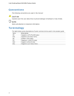
Intel Desktop Board DG41RQ Product Guide Conventions The following conventions are used in this manual: CAUTION Cautions warn the user about how to prevent damage to hardware or loss of data. NOTE Notes call attention to important information. Terminology The - Intel DG41RQ | Product Guide - Page 5
1 Desktop Board Features Desktop Board Components 11 Processor ...13 Main Memory...14 Intel® G41 Express Chipset 15 Audio Subsystem 16 Legacy Input/Output (I/O) Controller 17 LAN Subsystem 17 Hi-Speed USB 2.0 Support 18 Enhanced IDE Interface 18 Serial ATA...18 Expandability...19 BIOS ...19 - Intel DG41RQ | Product Guide - Page 6
BIOS Update File 58 Updating the BIOS with the ISO Image BIOS Update File 58 Updating the BIOS with the Iflash Memory Update Utility 59 Recovering the BIOS 60 A Error Messages and Indicators BIOS Beep Codes 61 BIOS Error Messages 61 B Regulatory Compliance Safety Standards 63 Place Battery - Intel DG41RQ | Product Guide - Page 7
of the BIOS Configuration Jumper Block 50 25. Removing the Battery 56 Tables 1. Feature Summary 9 2. Intel Desktop Board DG41RQ Components 12 3. Audio Jack Retasking Support 16 4. LAN Connector LEDs 18 5. Front Panel Audio Signal Names for Intel HD Audio 43 6. Front Panel Audio Header Signal - Intel DG41RQ | Product Guide - Page 8
Intel Desktop Board DG41RQ Product Guide viii - Intel DG41RQ | Product Guide - Page 9
This chapter briefly describes the features of Intel® Desktop Board DG41RQ. Table 1 summarizes the major features of the Desktop Board. Table 1. Feature Summary Form Factor Processor Main Memory Chipset Graphics Audio LAN Support Expansion Capabilities Peripheral Interfaces microATX (218.44 - Intel DG41RQ | Product Guide - Page 10
• Microsoft Windows XP Professional x64 Edition • Microsoft Windows XP Home Related Links: For more information about Intel Desktop Board DG41RQ, including the Technical Product Specification (TPS), BIOS updates, and device drivers, go to: http://support.intel.com/support/motherboards/desktop/ 10 - Intel DG41RQ | Product Guide - Page 11
Desktop Board Features Desktop Board Components Figure 1 shows the approximate location of the major components on Intel Desktop Board DG41RQ. Figure 1. Intel Desktop Board DG41RQ Components 11 - Intel DG41RQ | Product Guide - Page 12
more information about: • Intel Desktop Board DG41RQ • Supported processors • Audio software and utilities • LAN software and drivers http://www.intel.com/design/motherbd http://support.intel.com/support/motherboards/desktop http://processormatch.intel.com http://www.intel.com/design/motherbd http - Intel DG41RQ | Product Guide - Page 13
connects to the Desktop Board through the LGA775 socket (Figure 1, H). Go to the following page or link for more information about: • Instructions on installing or upgrading the processor, page 29 in Chapter 2 • Supported processors for Intel Desktop Board DG41RQ, http://processormatch.intel.com 13 - Intel DG41RQ | Product Guide - Page 14
Intel Desktop Board DG41RQ Product Guide Main Memory NOTE To be fully compliant with all applicable Intel ® SDRAM memory specifications, the board should be populated with DIMMs that support the Serial Presence Detect (SPD) data structure. If your memory modules do not support SPD, you will see a - Intel DG41RQ | Product Guide - Page 15
Desktop Board Features Intel® G41 Express Chipset The Intel G41 Express Chipset consists of the following devices: • Intel G41 Express Chipset Graphics and Memory Controller Hub (GMCH) with Direct Media Interface (DMI) • Intel 82801GB I/O Controller Hub (ICH7) with DMI The GMCH component provides - Intel DG41RQ | Product Guide - Page 16
Intel Desktop Board DG41RQ Product Guide Audio Subsystem The onboard audio subsystem consists of the following: • Intel® ICH7 • Realtek ALC662 audio codec • Back panel audio connectors • Onboard audio headers/connectors: ⎯ Front panel audio header supporting both Intel High Definition Audio and AC - Intel DG41RQ | Product Guide - Page 17
The subsystem features: • CSMA/CD protocol engine • LAN connect interface between ICH7 and the LAN controller • PCI bus power management Go to the following link for information about LAN software and drivers: http://support.intel.com/support/motherboards/desktop Two LEDs are built into the RJ-45 - Intel DG41RQ | Product Guide - Page 18
Intel Desktop Board DG41RQ Product Guide Table 4 describes the LED states when the board is powered up and the LAN subsystem is operating. Table 4. LAN Connector LEDs LED A B LED Color Green N/A Green Yellow LED State Off On Blinking Off On On Indicates LAN link is not established LAN link is - Intel DG41RQ | Product Guide - Page 19
expansion, the Desktop Board provides the following expansion slots: • One PCI Express x16 connector • Two PCI bus connectors BIOS The BIOS provides the Power-On Self-Test (POST), the BIOS Setup program, the PCI/PCI Express and IDE auto-configuration utilities, and the video BIOS. The BIOS is stored - Intel DG41RQ | Product Guide - Page 20
boot the computer. Related Links: For instructions on resetting the password, see Clearing Passwords on page 51. Hardware Management Features The hardware management features of Intel Desktop Board DG41RQ enable the board to be compatible with the Wired for Management (WfM) specification. The board - Intel DG41RQ | Product Guide - Page 21
Desktop Board Features Power Management Features Power management is implemented at several levels, including: • Software support through the Advanced Configuration and Power Interface (ACPI) • Hardware support: ⎯ Power connectors ⎯ Fan headers ⎯ LAN BIOS Setup program's Boot menu. The Desktop Board - Intel DG41RQ | Product Guide - Page 22
Intel Desktop Board DG41RQ Product Guide • All fan headers support closed-loop fan control that can adjust the fan speed according to thermal conditions. • All fan headers have a +12 V DC connection. The Desktop Board has a 4-pin processor fan header and a 3-pin rear chassis fan header. LAN Wake - Intel DG41RQ | Product Guide - Page 23
current requirements for the Desktop Board, refer to the Technical Product Specification by going to the following link, finding the product, and selecting Product Documentation from the left-hand menu: http://support.intel.com/support/motherboards/desktop/ Wake from USB Support NOTE Wake from USB - Intel DG41RQ | Product Guide - Page 24
is mounted on the Desktop Board. The speaker provides audible error code (beep code) information during the Power-On Self-Test (POST). Battery A battery on the Desktop Board keeps the values in CMOS RAM and the clock current when the computer is turned off. Go to page 52 for instructions on how to - Intel DG41RQ | Product Guide - Page 25
Desktop Board • Install and remove a processor • Install and remove memory • Install and remove a PCI Express x16 card • Connect the IDE and Serial ATA cables • Connect to the internal headers and connectors • Connect to the audio system • Connect chassis fan and power supply cables • Set the BIOS - Intel DG41RQ | Product Guide - Page 26
Intel Desktop Board DG41RQ Product Guide Installation Precautions When you install and test the Intel Desktop Board, observe all warnings and cautions in the installation instructions all warnings and cautions that instruct you to refer computer servicing to qualified technical personnel. Prevent - Intel DG41RQ | Product Guide - Page 27
transmissions, protects internal components from dust and foreign objects, and promotes correct airflow within the chassis. Install the I/O shield before installing the Desktop Board in the chassis. Place the shield inside the chassis as shown in Figure 4. Press the shield into place so that it fits - Intel DG41RQ | Product Guide - Page 28
Intel Desktop Board DG41RQ Product Guide Installing and Removing the Desktop Board CAUTION Only qualified manual for instructions on installing and removing the Desktop Board. Figure 5 shows the location of the mounting screw holes for Intel Desktop Board DG41RQ. Figure 5. Intel Desktop Board DG41RQ - Intel DG41RQ | Product Guide - Page 29
Installing and Replacing Desktop Board Components Installing and Removing a Processor Instructions on how to install the processor to the Desktop Board are given below. Installing a Processor CAUTION Before installing or removing the processor, make sure the AC power has been removed by unplugging - Intel DG41RQ | Product Guide - Page 30
Intel Desktop Board DG41RQ Product Guide 3. Lift the load plate (Figure 7, A). Do not touch the socket contacts (Figure 7, B). Figure 7. Lift the Load Plate 4. Remove the plastic protective socket cover from the load plate (Figure 8). Do not discard the protective socket cover. Always replace the - Intel DG41RQ | Product Guide - Page 31
Installing and Replacing Desktop Board Components 5. Remove the processor from the protective processor cover. Hold the processor only at the edges, being careful not to touch the bottom of the processor (Figure 9). Do not discard the protective processor cover. Always replace the processor cover if - Intel DG41RQ | Product Guide - Page 32
Intel Desktop Board DG41RQ Product Guide 7. Pressing down on the load plate (Figure 11, A), close and engage the socket lever (Figure 11, B). Figure 11. Close the Load Plate 32 - Intel DG41RQ | Product Guide - Page 33
Replacing Desktop Board Components Installing the Processor Fan Heat Sink Intel Desktop Board DG41RQ has mounting holes for a processor fan heat sink. For instructions on how to attach the processor fan heat sink to the Desktop Board, refer to the boxed processor manual. Connecting the Processor Fan - Intel DG41RQ | Product Guide - Page 34
Intel Desktop Board DG41RQ Product Guide Installing and Removing Memory NOTE To be fully compliant with all applicable Intel SDRAM memory specifications, the board requires DIMMs that support the Serial Presence Detect (SPD) data structure. The Desktop Board has two 240-pin DDR2 DIMM sockets - Intel DG41RQ | Product Guide - Page 35
Installing and Replacing Desktop Board Components Installing DIMMs To make sure you have the correct DIMM, place it on the illustration of the DDR2 DIMM in Figure 14. All the notches should match with the DDR2 DIMM. Figure 14. Use DDR2 DIMMs 35 - Intel DG41RQ | Product Guide - Page 36
Intel Desktop Board DG41RQ Product Guide To install a DIMM, follow these steps: 1. Observe the Remove the computer's cover and locate the DIMM sockets (see Figure 15). Figure 15. Installing a DIMM 4. Make sure the clips at either end of the DIMM socket(s) are pushed outward to the open position. - Intel DG41RQ | Product Guide - Page 37
you removed or disconnected to reach the DIMM sockets. 8. Replace the computer's cover and reconnect the AC power cord. Installing and Removing a PCI Express x16 Card CAUTION When installing a PCI Express x16 card on the Desktop Board, ensure that the card is fully seated in the PCI Express x16 - Intel DG41RQ | Product Guide - Page 38
Intel Desktop Board DG41RQ Product Guide Installing a PCI Express x16 Card CAUTION When installing a PCI Express x16 card on the Desktop Board, ensure that the card is fully seated in the PCI Express x16 connector before you power on the system. If the card is not fully seated in the PCI Express - Intel DG41RQ | Product Guide - Page 39
Installing and Replacing Desktop Board Components Removing the PCI Express x16 Card Follow these instructions to remove the PCI Express x16 card from the connector: 1. Observe the precautions in "Before You Begin" on page 25. 2. Remove the screw (Figure 17, A) that secures the card's metal bracket - Intel DG41RQ | Product Guide - Page 40
Intel Desktop Board DG41RQ Product Guide Connecting the IDE Cable The IDE cable can be used to connect two IDE drives to the Desktop Board. The cable supports the ATA-66/100 transfer protocol. Figure 18 shows the correct installation of the cable. NOTES ATA-66/100 compatible cables are backward - Intel DG41RQ | Product Guide - Page 41
Components Connecting the Serial ATA (SATA) Cables SATA cables support the Serial ATA protocol. Each cable can be used to connect a single internal SATA drive to the Desktop Board. For correct cable function: 1. Observe the precautions in "Before You Begin" on page 25. 2. Attach one end of the SATA - Intel DG41RQ | Product Guide - Page 42
Intel Desktop Board DG41RQ Product Guide Connecting to the Internal Headers and Connectors Before connecting cables to the internal headers and connectors, observe the precautions in "Before You Begin" on page 25. Figure 20 shows the location of the internal headers and connectors for Intel Desktop - Intel DG41RQ | Product Guide - Page 43
Installing and Replacing Desktop Board Components Front Panel Audio Header The front panel audio header shown in Figure 20, A on page 42 supports both High Definition (HD) Audio and AC'97 Audio. Table 5 shows the pin assignments and signal names for HD Audio and Table 6 shows the pin assignments - Intel DG41RQ | Product Guide - Page 44
Intel Desktop Board DG41RQ Product Guide Serial Port Header See Figure 20, C on page 42 for DCD 3 TXD# 5 Ground 7 RTS 9 RI Pin Signal Name 2 RXD# 4 DTR 6 DSR 8 CTS 10 No Connection Parallel Port Header See Figure 20, D on page 42 for the location of the serial port header. - Intel DG41RQ | Product Guide - Page 45
Installing and Replacing Desktop Board Components Front Panel Header Before connecting to the front panel header, observe the precautions in "Before You Begin" on page 25. See Figure 20, E on page 42 for the location of the multi-colored front panel header. Table 10 shows the pin assignments for - Intel DG41RQ | Product Guide - Page 46
Intel Desktop Board DG41RQ Product Guide USB 2.0 Headers Before connecting to the USB 2.0 headers, observe the A Pin Signal Name Pin 1 Power (+5 V) 2 3 D- 4 5 D+ 6 7 Ground 8 9 Key 10 Note: USB ports may be assigned as needed. USB Port B Signal Name Power (+5 V) DD+ Ground No - Intel DG41RQ | Product Guide - Page 47
Installing and Replacing Desktop Board Components Connecting to the Back Panel Audio Connectors After installing the audio driver from the Intel Express Installer CD-ROM, the multichannel audio feature can be enabled. Figure 21 shows the back panel audio connectors. The default connector assignments - Intel DG41RQ | Product Guide - Page 48
Intel Desktop Board DG41RQ Product Guide Connecting Chassis Fan and Power Supply Cables Connecting a Chassis Fan Cable Connect your chassis fan cable to the 3-pin rear chassis fan header on the Desktop Board. Figure 22 shows the location of the rear chassis fan header. Figure 22. Location of the - Intel DG41RQ | Product Guide - Page 49
may not function properly. The 2 x 12 pin main power connector on the Desktop Board is backwards compatible with ATX12V power supplies with 2 x 10 connectors. Figure 23 shows the location of the Desktop Board power connectors. Figure 23. Connecting Power Supply Cables 1. Observe the precautions in - Intel DG41RQ | Product Guide - Page 50
Intel Desktop Board DG41RQ Product Guide Setting the BIOS Configuration Jumper NOTE Always turn off the power and unplug the power cord from the computer before moving the jumper. Moving the jumper with the - Intel DG41RQ | Product Guide - Page 51
Desktop Board Components Clearing Passwords This procedure assumes that the board computer, turn on the computer, and allow it to boot. 7. The computer starts the Setup program. Setup displays the > to save the current values and exit Setup. 10. Turn off the computer. Disconnect the computer's power - Intel DG41RQ | Product Guide - Page 52
Intel Desktop Board DG41RQ Product Guide Replacing the Battery A coin-cell battery (CR2032) powers the real-time clock and CMOS memory. When the computer is not plugged into a wall socket, the battery has an estimated life of three years. When the computer is plugged in, the standby current from the - Intel DG41RQ | Product Guide - Page 53
Installing and Replacing Desktop Board Components VORSICHT Bei falschem Einsetzen einer neuen Batterie besteht Explosionsgefahr. Die Batterie darf nur durch denselben oder einen entsprechenden, vom Hersteller empfohlenen Batterietyp ersetzt werden. Entsorgen Sie verbrauchte Batterien den Anweisungen - Intel DG41RQ | Product Guide - Page 54
Intel Desktop Board DG41RQ Product Guide VIGYÁZAT Ha a telepet nem a megfelelő típusú telepre cseréli, az felrobbanhat. A telepeket lehetőség szerint újra kell hasznosítani. A használt telepeket a helyi környezetvédelmi - Intel DG41RQ | Product Guide - Page 55
Installing and Replacing Desktop Board Components UYARI Yanlış türde pil takıldığında patlama riski vardır. Piller mümkün olduğunda geri dönüştürülmelidir. Kullanılmış piller, yerel çevre yasalarına uygun olarak atılmalıdır. O 55 - Intel DG41RQ | Product Guide - Page 56
Intel Desktop Board DG41RQ Product Guide To replace the battery, follow these steps: 1. Observe the precautions in "Before You Begin" (see page 25). 2. Turn off all peripheral devices connected to the computer. Disconnect the computer's - Intel DG41RQ | Product Guide - Page 57
Intel® Flash Memory Update Utility and the ease of use of Windows-based installation wizards. To update the BIOS with the Intel Express BIOS Update utility: 1. Go to the Intel World Wide Web site: http://support.intel.com/support/motherboards/desktop/ 2. Navigate to the Intel Desktop Board DG41RQ - Intel DG41RQ | Product Guide - Page 58
: http://support.intel.com/support/motherboards/desktop Navigate to the Intel Desktop Board DG41RQ page, click "[view] Latest BIOS updates," and select the ISO Image BIOS Update or Iflash BIOS Update utility file. Updating the BIOS with the ISO Image BIOS Update File The ISO Image BIOS update allows - Intel DG41RQ | Product Guide - Page 59
boot from the hard drive if no key is pressed within 15 seconds. 5. At the "Welcome to the Intel Desktop Board BIOS Upgrade CD-ROM" page, press any key to confirm the BIOS upgrade operation. 6. Wait for the BIOS upgrade process to complete. CAUTION DO NOT POWER DOWN YOUR COMPUTER before the update - Intel DG41RQ | Product Guide - Page 60
Intel Desktop Board DG41RQ Product Guide 1. Uncompress the BIOS update file and copy the .BIO file, IFLASH.EXE, and .ITK file (optional) to a bootable USB flash drive or other bootable USB media. 2. Configure the BIOS or use the F10 option during POST to boot to the USB device. 3. Manually run the - Intel DG41RQ | Product Guide - Page 61
Intel Desktop Board DG41RQ reports POST errors in two ways: • By sounding a beep code • By displaying an error message on the monitor BIOS Beep Codes The BIOS also issues a beep code (one long tone followed by two short tones) during POST if the video configuration fails (a faulty video card - Intel DG41RQ | Product Guide - Page 62
Intel Desktop Board DG41RQ Product Guide 62 - Intel DG41RQ | Product Guide - Page 63
• Electromagnetic Compatibility (EMC) regulations • Product certifications Safety Standards Intel Desktop Board DG41RQ complies with the Battery Marking There is insufficient space on this Desktop Board to provide instructions for replacing and disposing of the Lithium ion coin cell battery - Intel DG41RQ | Product Guide - Page 64
Intel Desktop Board DG41RQ Product Guide European Union Declaration of Conformity Statement We, Intel Corporation, declare under our sole responsibility that the product Intel® Desktop Board DG41RQ is in conformity with all applicable essential requirements necessary for CE marking, following the - Intel DG41RQ | Product Guide - Page 65
consult http://www.intel.com/intel/other/ehs/product_ecology for the details of this program, including the scope of covered products, available locations, shipping instructions, terms and conditions, etc Intel Product Recycling Program http://www.intel.com/intel/other/ehs/product_ecology 65 - Intel DG41RQ | Product Guide - Page 66
Intel Desktop Board DG41RQ Product Guide Deutsch Als Teil von Intels Engagement für den Umweltschutz hat das Unternehmen das Intel Produkt-Recyclingprogramm implementiert, das Einzelhandelskunden von Intel , les instructions d'expédition, les conditions générales, etc. http://www.intel.com/in - Intel DG41RQ | Product Guide - Page 67
product. EU RoHS restricts the use of six materials. One of the six restricted materials is lead. Intel Desktop Board DG41RQ is lead-free although certain discrete components used on the board contain a small amount of lead which is necessary for component performance and/or reliability. This - Intel DG41RQ | Product Guide - Page 68
Intel Desktop Board DG41RQ Product Guide Table 17 shows the lead-free board markings as they appear on the board and accompanying collateral. Table 17. Lead-Free Board Markings Description Mark Lead-Free 2nd Level Interconnect: This symbol is used to identify electrical and electronic - Intel DG41RQ | Product Guide - Page 69
Regulations Intel Desktop Board DG41RQ complies with the EMC regulations stated in Table 18 when correctly installed in a compatible host V-3/2007.04, V-4/2007.04, Class B Title Title 47 of the Code of Federal Regulations, Part 15, Subpart B, Radio Frequency Devices. (USA instruction manual. 69 - Intel DG41RQ | Product Guide - Page 70
Intel Desktop Board DG41RQ Product Guide Korean Class B statement translation: This is household equipment that is certified to comply with EMC requirements. You may use this equipment in residential environments and other non-residential environments. Ensure Electromagnetic Compatibility (EMC) - Intel DG41RQ | Product Guide - Page 71
Description UL joint US/Canada Recognized Component mark. Includes adjacent UL file number for Intel Desktop Boards: E210882. Mark FCC Declaration of Conformity logo mark for Class B equipment. Includes Intel name and DG41RQ model designation. CE mark. Declaring compliance to European Union (EU - Intel DG41RQ | Product Guide - Page 72
Intel Desktop Board DG41RQ Product Guide Chassis and Component Certifications Ensure that the chassis and certain components , or ETL signifies compliance with safety requirements. Wiring and cables must also be UL listed or recognized and suitable for the intended use. The FCC Class B logo for home
-
 1
1 -
 2
2 -
 3
3 -
 4
4 -
 5
5 -
 6
6 -
 7
7 -
8
-
9
-
10
-
11
-
12
-
13
-
14
-
15
-
16
-
17
-
18
-
19
-
20
-
21
-
22
-
23
-
24
-
25
-
26
-
27
-
28
-
29
-
30
-
31
-
32
-
33
-
34
-
35
-
36
-
37
-
38
-
39
-
40
-
41
-
42
-
43
-
44
-
45
-
46
-
47
-
48
-
49
-
50
-
51
-
52
-
53
-
54
-
55
-
56
-
57
-
58
-
59
-
60
-
61
-
62
-
63
-
64
-
65
-
66
-
67
-
68
-
69
-
70
-
71
-
72
 |
 |

Intel
®
Desktop Board DG41RQ
Product Guide
Order Number:
E5913
7
-001