Intel DG41TY Product Guide
Intel DG41TY - Desktop Board Classic Series Motherboard Manual
 |
UPC - 735858204392
View all Intel DG41TY manuals
Add to My Manuals
Save this manual to your list of manuals |
Intel DG41TY manual content summary:
- Intel DG41TY | Product Guide - Page 1
Intel® Desktop Board DG41TY Product Guide Order Number: E52797-001 - Intel DG41TY | Product Guide - Page 2
at any time, without notice. Intel® Desktop Board DG41TY may contain design defects or errors known as errata which may cause the product to deviate from published specifications. Current characterized errata are available on request. Contact your local Intel sales office or your distributor to - Intel DG41TY | Product Guide - Page 3
equipment, etc. may not be supported without further evaluation by Intel. Document Organization The chapters in this Product Guide are arranged as follows: 1 Desktop Board Features: a summary of product features 2 Installing and Replacing Desktop Board Components: instructions on how to install the - Intel DG41TY | Product Guide - Page 4
Intel Desktop Board DG41TY Product Guide Conventions The following conventions are used in this manual: CAUTION Cautions warn the in the product guide. Term Description GB Gigabyte (1,073,741,824 bytes) GHz Gigahertz (one billion hertz) KB Kilobyte (1024 bytes) MB Megabyte (1,048,576 - Intel DG41TY | Product Guide - Page 5
Contents 1 Desktop Board Features Supported Operating Systems 10 Desktop Board Components 11 Processor ...13 Main Memory...13 Intel® G41 Express Chipset 14 Intel® G41 Graphics Subsystem 15 Intel® GMA X4500 Graphics Controller (Intel® GMA X4500 15 Audio Subsystem 16 Legacy Input/Output (I/O) - Intel DG41TY | Product Guide - Page 6
Intel Desktop Board DG41TY Product Guide Installing a Processor 31 Installing the Processor Fan Heat Sink 34 Connecting the Processor Fan Heat Statements 69 Recycling Considerations 69 Lead-Free Desktop Board 71 EMC Regulations 73 Ensure Electromagnetic Compatibility (EMC) Compliance 74 vi - Intel DG41TY | Product Guide - Page 7
52 25. Location of the BIOS Configuration Jumper Block 53 26. Removing the Battery 59 Tables 1. Feature Summary 9 2. Intel Desktop Board DG41TY Components 12 3. Audio Jack Retasking Support 16 4. LAN Connector LEDs 18 5. S/PDIF Connector 46 6. Jumper Settings for the Front Panel Audio Select - Intel DG41TY | Product Guide - Page 8
Intel Desktop Board DG41TY Product Guide 19. Lead-Free Board Markings 72 20. EMC Regulations 73 21. Product Certification Markings 75 viii - Intel DG41TY | Product Guide - Page 9
Intel® GMA X4500) • Intel® 82801G I/O Controller Hub (ICH7) • Intel G41 Express Chipset Graphics and Memory Controller Hub (GMCH) • Integrated graphics output for VGA and DVI-D • One PCI Express* x16 connector supporting PCI Express graphics cards • 5.1 + 2-channel onboard audio subsystem, featuring - Intel DG41TY | Product Guide - Page 10
Links: For more information about Intel Desktop Board DG41TY, including the Technical Product Specification (TPS), BIOS updates, and device drivers, go to: http://support.intel.com/support/motherboards/desktop/ Supported Operating Systems The Desktop Board supports the following operating systems - Intel DG41TY | Product Guide - Page 11
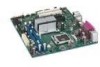
Desktop Board Features Desktop Board Components Figure 1 shows the approximate location of the major components on Intel Desktop Board DG41TY. Figure 1. Intel Desktop Board DG41TY Components 11 - Intel DG41TY | Product Guide - Page 12
Desktop Board DG41TY Product Guide Table 2. Intel Desktop Board DG41TY Components Label A B C D E F G H I J K L M N O P Q R S T U V WW X Y Z AA BB Description PCI bus connector 2 PCI bus connector 1 PCI Express x1 connector PCI Express x16 connector Rear chassis fan header (3-pin) - Intel DG41TY | Product Guide - Page 13
: • Intel Desktop Board DG41TY http://www.intel.com/design/motherbd http://support.intel.com/support/motherboards/desktop • Supported processors http://processormatch.intel.com • Audio software and utilities http://www.intel.com/design/motherbd • LAN software and drivers http://www.intel.com - Intel DG41TY | Product Guide - Page 14
information about: • SDRAM specifications, http://intel.com/technology/memory/ • Installing memory, page 36 in Chapter 2 • Tested memory, http://cmtlabs.com/mbsearch.asp Intel® G41 Express Chipset The Intel G41 Express Chipset consists of the following devices: • Intel G41 Express Chipset Graphics - Intel DG41TY | Product Guide - Page 15
Desktop Board Features Intel® G41 Graphics Subsystem The Intel G41 Express Chipset supports two separate, mutually exclusive graphics options. Either the integrated Intel® Graphics Media Accelerator X4500 (Intel® GMA X4500) graphics controller is used or a PCI Express x16 add-in card can be used. - Intel DG41TY | Product Guide - Page 16
Subwoofer No No No No Yes No No No No Yes Related Links: Go to the following link or pages for more information about: • Audio drivers and utilities http://support.intel.com/support/motherboards/desktop/ • The location of the back panel audio connectors, Figure 22 on page 50 16 - Intel DG41TY | Product Guide - Page 17
status LEDs The subsystem features: • CSMA/CD protocol engine • LAN connect interface between ICH7 and the LAN controller • PCI bus power management Related Links: Go to the following link for information about LAN software and drivers: http://support.intel.com/support/motherboards/desktop RJ-45 LAN - Intel DG41TY | Product Guide - Page 18
Intel Desktop Board DG41TY Product Guide Table 4 describes the LED states when the board is powered are backward compatible with USB 1.1 devices. USB 1.1 devices will function normally at USB 1.1 speeds. USB 2.0 support requires both an operating system and drivers that fully support USB 2.0 - Intel DG41TY | Product Guide - Page 19
Features (SPI) Flash component. The BIOS can be updated by following the instructions on page 61 in Chapter 3. Serial ATA and IDE Auto Configuration If IDE device. You can override the auto-configuration options by specifying manual configuration in the BIOS Setup program. PCI* and PCI Express - Intel DG41TY | Product Guide - Page 20
. Related Links: For instructions on resetting the password, see Clearing Passwords on page 54. Hardware Management Features The hardware management features of Intel Desktop Board DG41TY enable the board to be compatible with the Wired for Management (WfM) specification. The board has several - Intel DG41TY | Product Guide - Page 21
fans, that can adjust fan speed or switch the fans off as needed Chassis Intrusion The board supports a chassis security feature that detects if the chassis cover has been removed. The security feature uses a mechanical switch on the chassis that can be connected to the chassis intrusion header on - Intel DG41TY | Product Guide - Page 22
Intel Desktop Board DG41TY Product Guide Hardware Support Power Connectors ATX12V-compliant power supplies can turn either on or off). The computer's response can be set by using the Last Power State feature in the BIOS Setup program's Boot menu. The Desktop Board has two power connectors. See Figure - Intel DG41TY | Product Guide - Page 23
standby current. Failure to provide adequate standby current when using this feature can damage the power supply and/or effect ACPI S3 sleep state. The Desktop Board supports the PCI Bus Power Management Interface Specification. Add-in cards that support this specification can participate in power - Intel DG41TY | Product Guide - Page 24
DG41TY Product Guide Related Links: For more information on standby current requirements for the Desktop Board, refer to the Technical Product Specification by going to the following link, finding the product, and selecting Product Documentation from the left-hand menu: http://support.intel.com - Intel DG41TY | Product Guide - Page 25
Desktop Board Features Real-Time Clock The Desktop Board has a time-of-day clock and 100-year calendar. The battery on the Desktop Board keeps the clock current when the computer is turned off. 25 - Intel DG41TY | Product Guide - Page 26
Intel Desktop Board DG41TY Product Guide 26 - Intel DG41TY | Product Guide - Page 27
2 Installing and Replacing Desktop Board Components This chapter tells you how to: • Install the I/O shield • Install and remove the Desktop Board • Install and remove a processor • Install and remove memory • Install and remove a PCI Express x16 card • Connect the diskette drive cable • Connect the - Intel DG41TY | Product Guide - Page 28
DG41TY Product Guide Installation Precautions When you install and test the Intel Desktop Board, observe all warnings and cautions in the installation instructions circuit Observe all warnings and cautions that instruct you to refer computer servicing to qualified technical personnel. Prevent Power - Intel DG41TY | Product Guide - Page 29
Installing and Replacing Desktop Board Components Installing the I/O Shield The Desktop Board comes with an I/O shield. When installed in the chassis, the shield blocks radio frequency transmissions, protects internal components from dust and foreign objects, and promotes correct airflow within the - Intel DG41TY | Product Guide - Page 30
Intel Desktop Board DG41TY Product Guide Installing and Removing the Desktop Board CAUTION Only qualified manual for instructions on installing and removing the Desktop Board. Figure 5 shows the location of the mounting screw holes for Intel Desktop Board DG41TY. Figure 5. Intel Desktop Board DG41TY - Intel DG41TY | Product Guide - Page 31
should not be lit (see Figure 3 on page 23). Failure to do so could damage the processor and the board. To install a processor, follow these instructions: 1. Observe the precautions in "Before You Begin" on page 27. 2. Open the socket lever by pushing the lever down and away from the socket (Figure - Intel DG41TY | Product Guide - Page 32
Intel Desktop Board DG41TY Product Guide 3. Lift the load plate (Figure 7, A). Do not touch the socket contacts (Figure 7, B). Figure 7. Lift the Load Plate 4. Remove the plastic protective socket cover from the - Intel DG41TY | Product Guide - Page 33
Installing and Replacing Desktop Board Components 5. Remove the processor from the protective processor cover. Hold the processor only at the edges, being careful not to touch the bottom of the processor (see Figure 9). Do not discard the protective processor cover. Always replace the processor - Intel DG41TY | Product Guide - Page 34
Board DG41TY Product Guide 7. Pressing down on the load plate (Figure 11, A), close and engage the socket lever (Figure 11, B). Figure 11. Close the Load Plate Installing the Processor Fan Heat Sink Intel Desktop Board DG41TY has mounting holes for a processor fan heat sink. For instructions on - Intel DG41TY | Product Guide - Page 35
Installing and Replacing Desktop Board Components Connecting the Processor Fan Heat Sink Cable Connect the processor fan heat sink cable to the 4-pin processor fan header (see Figure 12). A fan with a 4-pin connector as shown in Figure 12, A is recommended; however, a fan with a 3-pin connector ( - Intel DG41TY | Product Guide - Page 36
Intel Desktop Board DG41TY Product Guide Removing the Processor For instructions on how to remove the processor fan heat sink and processor, refer to the processor installation manual. Installing and Removing Memory NOTE To be fully compliant with all applicable Intel SDRAM memory specifications, - Intel DG41TY | Product Guide - Page 37
Installing and Replacing Desktop Board Components Installing DIMMs To make sure you have the correct DIMM, place it on the illustration of the DDR2 DIMM in Figure 14. All the notches should match with the DDR2 DIMM. Figure 14. Use DDR2 DIMMs 37 - Intel DG41TY | Product Guide - Page 38
Intel Desktop Board DG41TY Product Guide To install a DIMM, follow these steps: 1. Observe the precautions in "Before You Begin" on page 27. 2. Turn off all peripheral devices connected to the computer. - Intel DG41TY | Product Guide - Page 39
Installing and Replacing Desktop Board Components 7. Insert the bottom edge of the DIMM into the socket. 8. When the DIMM is inserted, push down on the top edge of the DIMM until the retaining clips snap into place. Make sure the clips are firmly in place. 9. Replace the computer's cover and - Intel DG41TY | Product Guide - Page 40
Intel Desktop Board DG41TY Product Guide Installing a PCI Express x16 Card CAUTION When installing a PCI Express x16 card on the desktop board, ensure that the card is fully seated in the - Intel DG41TY | Product Guide - Page 41
Installing and Replacing Desktop Board Components Removing the PCI Express x16 Card Follow these instructions to remove the PCI Express x16 card from the connector: 1. Observe the precautions in "Before You Begin" on page 27. 2. Remove the screw (Figure 17, A) - Intel DG41TY | Product Guide - Page 42
Intel Desktop Board DG41TY Product Guide Connecting the Diskette Drive Cable The diskette drive cable Begin" on page 27. 2. Attach the cable end labeled P1 to the diskette drive connector on the Intel Desktop Board (Figure 18, A). 3. Attach the cable end labeled P2 to the diskette drive (Figure 18 - Intel DG41TY | Product Guide - Page 43
supports the ATA-66/100 transfer protocol. Figure 19 shows the correct installation of the cable. NOTES ATA-66/100 compatible cables are backward compatible 27. 2. Attach the cable end with the single connector (blue) to the Intel Desktop Board (Figure 19, A). 3. Attach the cable end with the two - Intel DG41TY | Product Guide - Page 44
Intel Desktop Board DG41TY Product Guide Connecting the Serial ATA (SATA) Cables SATA cables support the Serial ATA protocol. Each cable can be used to connect a single internal SATA drive to the Desktop Board. For correct cable function: 1. Observe the - Intel DG41TY | Product Guide - Page 45
headers and connectors, observe the precautions in "Before You Begin" on page 27. Figure 21 shows the location of the internal headers and connectors for Intel Desktop Board DG41TY. Figure 21. Internal Headers and Connectors 45 - Intel DG41TY | Product Guide - Page 46
Intel Desktop Board DG41TY Product Guide S/PDIF Connector Figure 21, A on page 45 shows the location Ground Front Panel Audio Header The front panel audio header shown in Figure 21, B on page 45 supports both High Definition (HD) Audio and AC'97 Audio. Table 7 shows the pin assignments and signal - Intel DG41TY | Product Guide - Page 47
Installing and Replacing Desktop Board Components Table 8. Front Panel Audio Header Signal Names for AC'97 Audio Pin Signal Name 1 MIC 3 MIC_BIAS 5 FP_OUT_R 7 AUD_5V 9 FP_OUT_L Pin Signal Name 2 AUD_GND 4 AUD_GND 6 FP_RETURN_R 8 KEY (no pin) 10 FP_RETURN_L Serial Port - Intel DG41TY | Product Guide - Page 48
Intel Desktop Board DG41TY Product Guide Chassis Intrusion Header Figure 21, E on page 45 shows the location of the chassis intrusion header. This header can be connected to a mechanical switch on - Intel DG41TY | Product Guide - Page 49
Installing and Replacing Desktop Board Components Alternate Front Panel Power LED Header Figure 21, G on page 45 shows the location of the alternate front panel power LED header. Pins 1 and 3 of this header duplicate the signals on pins 2 and 4 of the front panel header. If your chassis has a three - Intel DG41TY | Product Guide - Page 50
Desktop Board DG41TY Product Guide Connecting to the Back Panel Audio Connectors After installing the audio driver from the Intel Express Installer CD-ROM, the multichannel audio feature can be enabled. Figure 22 shows the back panel audio connectors. The default connector assignments are shown - Intel DG41TY | Product Guide - Page 51
Installing and Replacing Desktop Board Components Connecting Chassis Fan and Power Supply Cables Connecting Chassis Fan Cables Connect chassis fan cables to the 3-pin chassis fan headers on the Desktop Board. Figure 23 shows the location of the chassis fan headers. Figure 23. Location of the Chassis - Intel DG41TY | Product Guide - Page 52
Intel Desktop Board DG41TY Product Guide Connecting Supply Power Cables CAUTION Failure to use an appropriate function properly. The 2 x 12 pin main power connector on the Desktop Board is backwards compatible with ATX12V power supplies with 2 x 10 connectors. Figure 24 shows the location of the - Intel DG41TY | Product Guide - Page 53
Installing and Replacing Desktop Board Components Setting the BIOS Configuration Jumper NOTE Always turn off the power and unplug the power cord from the computer before moving the jumper. Moving the jumper with the power on may result in unreliable computer operation. Figure 25 shows the location - Intel DG41TY | Product Guide - Page 54
Intel Desktop Board DG41TY Product Guide Clearing Passwords This procedure assumes that the board is installed in the computer and the configuration jumper block is set to normal mode. 1. Observe the - Intel DG41TY | Product Guide - Page 55
Installing and Replacing Desktop Board Components Replacing the Battery A coin-cell battery (CR2032) powers the real-time clock and CMOS memory. When the computer is not plugged into a wall socket, the battery has an estimated life of three years. When the computer is plugged in, the standby current - Intel DG41TY | Product Guide - Page 56
Intel Desktop Board DG41TY Product Guide VORSICHT Bei falschem Einsetzen einer neuen baterias devem ser recicladas nos locais apropriados. A eliminação de baterias usadas deve ser feita de acordo com as regulamentações ambientais da região. AŚCIAROŽZNA UPOZORNÌNÍ V případě výměny baterie za nesprá - Intel DG41TY | Product Guide - Page 57
Installing and Replacing Desktop Board Components VIGYÁZAT Ha a telepet nem a megfelelő típusú telepre cseréli, az felrobbanhat. A telepeket lehetőség szerint újra kell hasznosítani. A használt telepeket a helyi környezetvédelmi előírásoknak megfelelően kell kiselejtezni. AWAS Risiko letupan wujud - Intel DG41TY | Product Guide - Page 58
Intel Desktop Board DG41TY Product Guide UYARI Yanlış türde pil takıldığında patlama riski vardır. Piller mümkün olduğunda geri dönüştürülmelidir. Kullanılmış piller, yerel çevre yasalarına uygun olarak atılmalıdır. O 58 - Intel DG41TY | Product Guide - Page 59
Installing and Replacing Desktop Board Components To replace the battery, follow these steps: 1. Observe the precautions in "Before You Begin" (see page 27). 2. Turn off all peripheral devices connected to the computer. Disconnect the computer's power cord from the AC power source (wall outlet or - Intel DG41TY | Product Guide - Page 60
Intel Desktop Board DG41TY Product Guide 60 - Intel DG41TY | Product Guide - Page 61
the Intel Express BIOS Update utility: 1. Go to the Intel World Wide Web site: http://support.intel.com/support/motherboards/desktop/ 2. Navigate to the Intel Desktop Board DG41TY page, runs the update program. 6. Follow the instructions provided in the dialog boxes to complete the BIOS update. 61 - Intel DG41TY | Product Guide - Page 62
Intel Desktop Board DG41TY Product Guide Updating the BIOS with the ISO Image BIOS Update by navigating to the Intel Desktop Board DG41TY page on the Intel World Wide Web site at: http://support.intel.com/support/motherboards/desktop Navigate to the Intel Desktop Board DG41TY page, click "[view] - Intel DG41TY | Product Guide - Page 63
flash drive, or other bootable USB media. The utility available on the Intel World Wide Web site provides a simple method for creating a bootable CD-ROM that will automatically section of the BIOS NOTE Review the instructions distributed with the update utility before attempting a BIOS update. 63 - Intel DG41TY | Product Guide - Page 64
Intel Desktop Board DG41TY Product Guide to the USB device. 3. Manually run the IFLASH.EXE file from the USB device and manually update the BIOS. Recovering the BIOS the Intel Desktop Board BIOS or recovering from a BIOS update failure, go to: http://support.intel.com/support/motherboards/desktop - Intel DG41TY | Product Guide - Page 65
A Error Messages and Indicators Intel Desktop Board DG41TY reports POST errors in two ways: • By sounding a beep code • By recoverable error occurs during the POST, the BIOS displays an error message describing the problem. Table 17 gives an explanation of the BIOS error messages. Table 17. - Intel DG41TY | Product Guide - Page 66
Intel Desktop Board DG41TY Product Guide 66 - Intel DG41TY | Product Guide - Page 67
statements • Electromagnetic Compatibility (EMC) regulations • Product certifications Safety Standards Intel Desktop Board DG41TY complies with the Marking There is insufficient space on this Desktop Board to provide instructions for replacing and disposing of the Lithium ion coin cell battery. - Intel DG41TY | Product Guide - Page 68
Intel Desktop Board DG41TY Product Guide European Union Declaration of Conformity Statement We, Intel Corporation, declare under our sole responsibility that the product Intel® Desktop Board DG41TY is in conformity with all applicable essential requirements necessary for CE marking, following the - Intel DG41TY | Product Guide - Page 69
Portuguese Este produto cumpre com as normas da intel.com/intel/other/ehs/product_ecology for the details of this program, including the scope of covered products, available locations, shipping instructions, terms and conditions, etc Intel Product Recycling Program http://www.intel.com/intel - Intel DG41TY | Product Guide - Page 70
Intel Desktop Board DG41TY Product Guide Deutsch Als Teil von Intels Engagement für den Umweltschutz hat das Unternehmen das Intel Produkt-Recyclingprogramm implementiert, das Einzelhandelskunden von Intel , les instructions d'expédition, les conditions générales, etc. http://www.intel.com/in tel - Intel DG41TY | Product Guide - Page 71
Intel usados para locais selecionados, onde esses produtos são reciclados de maneira adequada. Consulte o site http://www.intel.com/intel/ six materials. One of the six restricted materials is lead. Intel Desktop Board DG41TY is lead-free although certain discrete components used on the board - Intel DG41TY | Product Guide - Page 72
Intel Desktop Board DG41TY Product Guide Table 19 shows the lead-free board markings as they China RoHS/Environmentally Friendly Use Period Logo: This is an example of the symbol used on Intel Desktop Boards and associated collateral. The color of the mark may vary depending upon the application. - Intel DG41TY | Product Guide - Page 73
Regulatory Compliance EMC Regulations Intel Desktop Board DG41TY complies with the EMC regulations stated in Table 20 when correctly installed in a compatible host system. Table 20. EMC Regulations Regulation interference. Install and use the equipment according to the instruction manual. 73 - Intel DG41TY | Product Guide - Page 74
Intel Desktop Board DG41TY Product Guide Korean Class B statement translation: This is household equipment that is certified to comply with EMC requirements. You may use this equipment in residential environments and other non-residential environments. Ensure Electromagnetic Compatibility (EMC) - Intel DG41TY | Product Guide - Page 75
(Korean Communications Commission) EMC certification mark. Includes adjacent KCC certification number: CPU-DG41TY (B). Taiwan BSMI (Bureau of Standards, Metrology, and Inspections) mark. Includes adjacent Intel company number, D33025. Printed wiring board manufacturer's recognition mark. Consists - Intel DG41TY | Product Guide - Page 76
Intel Desktop Board DG41TY Product Guide Chassis and Component Certifications Ensure that the chassis Radio and Telecommunications Terminal Equipment (R&TTE) directive may also apply depending on product features. In the United States A certification mark by a Nationally Recognized Testing Laboratory
-
 1
1 -
 2
2 -
 3
3 -
 4
4 -
 5
5 -
 6
6 -
 7
7 -
8
-
9
-
10
-
11
-
12
-
13
-
14
-
15
-
16
-
17
-
18
-
19
-
20
-
21
-
22
-
23
-
24
-
25
-
26
-
27
-
28
-
29
-
30
-
31
-
32
-
33
-
34
-
35
-
36
-
37
-
38
-
39
-
40
-
41
-
42
-
43
-
44
-
45
-
46
-
47
-
48
-
49
-
50
-
51
-
52
-
53
-
54
-
55
-
56
-
57
-
58
-
59
-
60
-
61
-
62
-
63
-
64
-
65
-
66
-
67
-
68
-
69
-
70
-
71
-
72
-
73
-
74
-
75
-
76
 |
 |

Intel
®
Desktop Board DG41TY
Product Guide
Order Number:
E52797-001