Intel DG965OT Product Guide
Intel DG965OT - Desktop Board Motherboard Manual
 |
UPC - 735858186049
View all Intel DG965OT manuals
Add to My Manuals
Save this manual to your list of manuals |
Intel DG965OT manual content summary:
- Intel DG965OT | Product Guide - Page 1
Intel® Desktop Board DG965OT Product Guide Order Number: D63605-003 - Intel DG965OT | Product Guide - Page 2
Intel® Desktop Board DG965OT Product Guide Second release of the Intel® Desktop Board DG965OT Product Guide Added operating system support and updated installed and used in accordance with the instructions, may cause harmful interference to radio communications. However, there is no guarantee that - Intel DG965OT | Product Guide - Page 3
how to install the desktop board and other hardware components 3 Updating the BIOS: instructions on how to update the BIOS 4 Configuring for RAID (Intel® Matrix Storage Technology): information about configuring your system for RAID 5 Intel® Quick Resume Technology Driver (Intel® QRTD): information - Intel DG965OT | Product Guide - Page 4
million hertz) Box Contents • Intel Desktop Board DG965OT • I/O shield • One diskette drive cable • One ATA-66/100 cable • Two locking Serial ATA cables • Back panel audio port covers • Intel® Express Installer DVD-ROM • Intel® Matrix Storage Technology RAID driver diskette • Quick Reference poster - Intel DG965OT | Product Guide - Page 5
Contents 1 Desktop Board Features Supported Operating Systems 10 Desktop Board Components 11 Processor ...13 Main Memory ...13 Intel® G965 Express Chipset 14 Intel G965 Graphics Subsystem 15 Onboard Audio Subsystem 16 Input/Output (I/O) Controller 17 LAN Subsystem 17 LAN Subsystem Software - Intel DG965OT | Product Guide - Page 6
Intel Desktop Board DG965OT Product Guide Installing and Removing a Processor 29 Installing a Processor 29 Installing the Processor Fan Heat Sink 32 Connecting the Processor Fan Heat Sink Cable 32 Removing the Processor 33 Installing and Removing Memory 33 Guidelines for Dual Channel Memory - Intel DG965OT | Product Guide - Page 7
17 3. Location of Standby Power Indicator 23 4. Installing the I/O Shield 27 5. Desktop Board DG965OT Mounting Screw Hole Locations 28 6. Lift Socket Lever 29 7. Lift the Load Plate 29 8. Remove the Protective Socket Cover 30 9. Remove the Processor from the Protective Processor Cover 30 10 - Intel DG965OT | Product Guide - Page 8
Intel Desktop Board DG965OT Product Guide 30. Original SATA Port Mapping for Desktop Board DG965OT 63 31. SATA Port Mapping for Desktop Board DG965OT After RAID is Enabled 64 Tables 1. Feature Summary 9 2. Desktop Board DG965OT Components 12 3. LAN Connector LED States 18 4. Front Panel Audio - Intel DG965OT | Product Guide - Page 9
describes the main features of Intel® Desktop Board DG965OT. Table 1 summarizes the major features of the desktop board. Table 1. Feature Summary Form Factor Processor Main Memory Chipset Graphics Audio Expansion Capabilities Peripheral Interfaces LAN Support microATX (243.84 millimeters [9.60 - Intel DG965OT | Product Guide - Page 10
(Intel® QST) fan speed control Related Links: For more information about Desktop Board DG965OT, including the Technical Product Specification (TPS), BIOS updates, and device drivers, go to: http://support.intel.com/support/motherboards/desktop/ Supported Operating Systems The desktop board supports - Intel DG965OT | Product Guide - Page 11
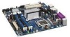
Desktop Board Features Desktop Board Components Figure 1 shows the approximate location of the major components on Desktop Board DG965OT. Figure 1. Desktop Board DG965OT Components 11 - Intel DG965OT | Product Guide - Page 12
for more information about: • Desktop Board DG965OT • Supported processors • Audio software and utilities • LAN software and drivers http://www.intel.com/design/motherbd http://support.intel.com/support/motherboards/desktop http://www.intel.com/go/findCPU http://www.intel.com/design/motherbd http - Intel DG965OT | Product Guide - Page 13
purchased separately. The processor connects to the desktop board through the LGA775 socket. The supported processors list for Desktop Board DG965OT is located on the web at: http://www.intel.com/go/findCPU Related Links: Go to the following links or pages for more information about: • Instructions - Intel DG965OT | Product Guide - Page 14
Intel Desktop Board DG965OT Product Guide ― Memory configurations listed below: • Up to 2.0 GB utilizing 256 Mb technology • Up to 4.0 GB utilizing 512 Mb or 1 Gb technology • Up to 8.0 GB utilizing 1 Gb technology NOTE 1 Gb memory technology is not supported on DDR2-800 DIMMs. Intel recommends - Intel DG965OT | Product Guide - Page 15
Desktop Board Features Intel G965 Graphics Subsystem The Intel G965 Express Chipset contains two separate, mutually exclusive graphics options. Either the integrated GMA X3000 graphics controller is used or a PCI Express x16 add-in card can be used. When a PCI Express x16 add-in card is installed, - Intel DG965OT | Product Guide - Page 16
― Mic in/retasking jack Related Links: Go to the following link or pages for more information about: • Audio drivers and utilities http://support.intel.com/support/motherboards/desktop/ • Installing the front panel audio solution, page 43 • The location of audio connectors, Figure 23 on page 46 16 - Intel DG965OT | Product Guide - Page 17
Connection • RJ-45 connector with status indicator LEDs LAN Subsystem Software For LAN software and drivers, refer to the DG965OT link on Intel's World Wide Web site at: http://support.intel.com/support/motherboards/desktop RJ-45 LAN Connector LEDs Two LEDs are built into the RJ-45 LAN connector - Intel DG965OT | Product Guide - Page 18
Hi-Speed USB in the BIOS reverts all USB 2.0 ports to USB 1.1 operation. This may be required to accommodate operating systems that do not support USB 2.0. Enhanced IDE Interface The desktop board's IDE interface handles the exchange of information between the processor and peripheral devices such - Intel DG965OT | Product Guide - Page 19
PCI bus connectors BIOS The BIOS provides the Power-On Self-Test (POST), the BIOS Setup program, the PCI/PCI Express and IDE auto-configuration utilities, and the video BIOS. The BIOS is stored in a Serial Peripheral Interface (SPI) Flash device. The BIOS can be updated by following the instructions - Intel DG965OT | Product Guide - Page 20
Product Guide Hardware Management Features The hardware management features of Desktop Board DG965OT enable the board to be compatible with the Wired for Management (WfM) specification. The board has several hardware management features including the following: • Fan speed monitoring and control - Intel DG965OT | Product Guide - Page 21
input of the hardware monitoring and control device. • All fan headers support closed-loop fan control that can adjust the fan speed or switch the fan on or off as needed. • All fan headers have a +12 V dc connection. The desktop board has a 4-pin processor fan header and two 3-pin chassis - Intel DG965OT | Product Guide - Page 22
by a wake-up device or event, the computer quickly returns to its last known awake state. The desktop board supports the PCI Bus Power Management Interface Specification. Add-in cards that support this specification can participate in power management and can be used to wake the computer. 22 - Intel DG965OT | Product Guide - Page 23
on standby current requirements for the desktop board, refer to the Technical Product Specification by going to the following link, finding the product, and selecting Product Documentation from the left-hand menu: http://support.intel.com/support/motherboards/desktop/ Resume on Ring Resume on Ring - Intel DG965OT | Product Guide - Page 24
Intel Desktop Board DG965OT Product Guide Wake from USB NOTE Wake from USB requires the use of a USB peripheral that supports Wake from USB. USB bus activity wakes the computer from an ACPI S3 state. Wake from PS/2 Keyboard/Mouse PS/2 keyboard/mouse activity wakes the - Intel DG965OT | Product Guide - Page 25
I/O shield • Install and remove the desktop board • Install and remove a processor • Install and remove memory • Install and remove a PCI Express x16 card • Connect the IDE and Serial ATA cables • Connect to the internal headers • Connect the flexible audio system • Connect the chassis fan and power - Intel DG965OT | Product Guide - Page 26
Intel Desktop Board DG965OT Product Guide Installation Precautions When you install and test the Intel desktop board, observe all warnings and cautions in the installation instructions. To avoid injury, be careful of: • Sharp pins on connectors • Sharp pins on printed circuit assemblies • Rough - Intel DG965OT | Product Guide - Page 27
components from dust and foreign objects, and promotes correct airflow within the chassis. Install the I/O shield before installing the desktop board in the chassis. Place the shield inside the chassis as shown in Figure 4. Press the shield into place so that it fits tightly and securely. If the - Intel DG965OT | Product Guide - Page 28
computer can result in personal injury or equipment damage. Refer to your chassis manual for instructions on installing and removing the desktop board. Figure 5 shows the location of the mounting screw holes for Desktop Board DG965OT. Figure 5. Desktop Board DG965OT Mounting Screw Hole Locations 28 - Intel DG965OT | Product Guide - Page 29
Replacing Desktop Board Components Installing and Removing a Processor Instructions on how to install the processor on the desktop board are given below. Installing a Processor CAUTION Before installing or removing the processor, make sure the AC power has been removed by unplugging the power cord - Intel DG965OT | Product Guide - Page 30
Intel Desktop Board DG965OT Product Guide 4. Remove the plastic protective socket cover from the load plate (see Figure 8). Do not discard the protective socket cover. Always replace the socket cover if the processor is removed from the socket. Figure 8. Remove the Protective Socket Cover 5. Remove - Intel DG965OT | Product Guide - Page 31
Installing and Replacing Desktop Board Components 6. Hold the processor with your thumb and index fingers oriented as shown in Figure 10. Make sure fingers align to the socket cutouts (Figure 10, A). Align notches (Figure 10, B) with the socket (Figure 10, C). Lower the processor straight down - Intel DG965OT | Product Guide - Page 32
Product Guide Installing the Processor Fan Heat Sink Desktop Board DG965OT has an integrated processor fan heat sink retention mechanism (RM). For instructions on how to attach the processor fan heat sink to the integrated processor fan heat sink RM, refer to the boxed processor manual or the Intel - Intel DG965OT | Product Guide - Page 33
applicable Intel SDRAM memory specifications, the board requires DIMMs that support the Serial Presence Detect (SPD) data structure. You can access the PC Serial Presence Detect Specification at: http://www.intel.com/technology/memory/ddr/specs/dda18c32_64_128x72ag_a.pdf Desktop Board DG965OT has - Intel DG965OT | Product Guide - Page 34
Intel Desktop Board DG965OT Product Guide If additional memory is to be used, install another matched pair of DIMMs in DIMM 1 (black) in both channels A and B (see Figure 14). Figure 14. Dual Channel Memory Configuration Example 2 Three DIMMs Install a matched pair of DIMMs equal in speed and size - Intel DG965OT | Product Guide - Page 35
Installing and Replacing Desktop Board Components Installing DIMMs To make sure you have the correct DIMM, place it on the illustration of the DDR2 DIMM in Figure 16. All the notches should match with the DDR2 DIMM. Figure 16. Use DDR2 DIMMs 35 - Intel DG965OT | Product Guide - Page 36
Intel Desktop Board DG965OT Product Guide NOTE Memory must be installed in the Channel A, DIMM 0 socket to enable Intel® Quiet System Technology. To install a DIMM, follow these steps: 1. Observe the precautions in "Before You Begin" on page 25. 2. Turn off all peripheral devices connected - Intel DG965OT | Product Guide - Page 37
Installing and Replacing Desktop Board Components Removing DIMMs To remove a DIMM, follow these steps: 1. Observe the precautions in "Before You Begin" on page 25. 2. Turn off all peripheral devices connected to the computer. Turn off the computer. 3. Remove the AC power cord from the computer. 4. - Intel DG965OT | Product Guide - Page 38
Intel Desktop Board DG965OT Product Guide Installing and Removing a PCI Express x16 Card CAUTION When installing a PCI Express x16 card on the desktop board, ensure that the card is fully seated in the PCI Express x16 connector before you power on the system. If the card is not fully seated in the - Intel DG965OT | Product Guide - Page 39
Installing and Replacing Desktop Board Components Removing the PCI Express x16 Card Follow these instructions to remove the PCI Express x16 card from the connector: 1. Observe the precautions in "Before You Begin" on page 25. 2. Remove the screw (Figure 19, A) that secures the card's metal bracket - Intel DG965OT | Product Guide - Page 40
Intel Desktop Board DG965OT Product Guide Connecting the IDE Cable The IDE cable can connect two drives to the desktop board. The cable supports the ATA-66/100 transfer protocol. Figure 20 shows the correct installation of the cable. NOTES ATA-66/100 compatible cables are backward compatible with - Intel DG965OT | Product Guide - Page 41
ATA (SATA) Cable The SATA cable supports the Serial ATA protocol and connects a single drive to the desktop board. For correct cable function: 1. Observe the precaution in "Before You Begin" on page 25. 2. Attach the locking cable end to the connector on the board (Figure 21, A). 3. Attach the cable - Intel DG965OT | Product Guide - Page 42
Intel Desktop Board DG965OT Product Guide Connecting to Internal Headers Before connecting cables to the internal headers, observe the precautions in "Before You Begin" on page 25. Figure 22 shows the location of the internal headers. Item Description A HD Audio Link B IEEE 1394a C Front - Intel DG965OT | Product Guide - Page 43
and Replacing Desktop Board Components Installing a Front Panel Audio Solution for Intel® High Definition Audio Figure 22, C on page 42 shows the location of the yellow front panel audio header. Table 4 shows the pin assignments for the front panel audio header. Table 4. Front Panel Audio Header - Intel DG965OT | Product Guide - Page 44
Intel Desktop Board DG965OT Product Guide To restore back panel audio, follow these steps: 1. Observe the precautions in "Before You Begin" on page 25. 2. Turn off all peripheral devices connected to the computer. Turn off the computer and disconnect the AC power cord. 3. Remove the cover. 4. - Intel DG965OT | Product Guide - Page 45
Installing and Replacing Desktop Board Components Connecting to the Alternate Front Panel Power LED Header Figure 22, E on page 42 shows the location of the alternate front panel power LED header. Pins 1 and 3 of this header duplicate the signals on pins 2 and 4 of the front panel header. If your - Intel DG965OT | Product Guide - Page 46
Intel Desktop Board DG965OT Product Guide Connecting to the HD Audio Link Header See Figure 22, A for the location of the HD Audio Link header. Table 9 shows the pin assignments for the header. Table 11. HD Audio Link Header Signal Names Pin Signal Name Pin Signal Name 1 BLCK 3 RST 5 SYNC 2 - Intel DG965OT | Product Guide - Page 47
and Replacing Desktop Board Components Connecting Chassis Fan and Power Cables Connecting Chassis Fan Cables Connect the chassis fan cables to the two chassis fan headers on the desktop board. Figure 24 shows the location of the chassis fan headers. Figure 24. Location of Chassis Fan Headers 47 - Intel DG965OT | Product Guide - Page 48
Intel Desktop Board DG965OT Product Guide Connecting Power Cables CAUTION Failure to use the appropriate power supply and/or not connecting the 12 V (2 x 2 pin) power connector to the desktop board may result in damage to the board or the system may not function properly. The 2 x 12 pin main power - Intel DG965OT | Product Guide - Page 49
Connectors and Headers Figure 26 shows the location of the other connectors and headers on the desktop board. Item Description A PCI bus connector 2 B PCI bus connector 1 C PCI Express x1 connector D Diskette drive connector D Chassis intrusion header Figure 26. Location of Other Connectors and - Intel DG965OT | Product Guide - Page 50
Intel Desktop Board DG965OT Product Guide Setting the BIOS Configuration Jumper NOTE Always turn off the power and unplug the power cord from the computer before moving the jumper. Moving the jumper with the power on may result in unreliable computer operation. Figure 27 shows the location of the - Intel DG965OT | Product Guide - Page 51
Installing and Replacing Desktop Board Components The three-pin BIOS jumper block enables all board configurations to be done in the BIOS Setup program. Table 12 shows the jumper settings for the BIOS Setup program modes. Table 12. Jumper Settings for the BIOS Setup Program Modes Jumper Setting - Intel DG965OT | Product Guide - Page 52
Intel Desktop Board DG965OT Product Guide Back Panel Connectors NOTE The line out connector, located on the back panel, is designed to power either headphones or amplified speakers only. Poor audio quality may occur if passive (nonamplified) speakers are connected to this output. Figure 28 shows the - Intel DG965OT | Product Guide - Page 53
Installing and Replacing Desktop Board Components Replacing the Battery A coin-cell battery (CR2032) powers the real-time clock and CMOS memory. When the computer is not plugged into a wall socket, the battery has an estimated life of three years. When the computer is plugged in, the - Intel DG965OT | Product Guide - Page 54
Intel Desktop Board DG965OT Product Guide VORSICHT Bei falschem Einsetzen einer neuen Batterie besteht Explosionsgefahr. Die Batterie darf nur durch denselben oder einen entsprechenden, vom Hersteller empfohlenen Batterietyp ersetzt werden. Entsorgen - Intel DG965OT | Product Guide - Page 55
Installing and Replacing Desktop Board Components VIGYAZAT Ha a telepet nem a megfelelő típusú telepre cseréli, az felrobbanhat. A telepeket lehetőség szerint újra kell hasznosítani. A használt telepeket a helyi környezetvédelmi - Intel DG965OT | Product Guide - Page 56
Intel Desktop Board DG965OT Product Guide . UYARI Yanlış türde pil takıldığında patlama riski vardır. Piller mümkün olduğunda geri dönüştürülmelidir. Kullanılmış piller, yerel çevre yasalarına uygun olarak atılmalıdır. O 56 - Intel DG965OT | Product Guide - Page 57
and Replacing Desktop Board Components To replace the battery, follow these steps: 1. Observe the precautions in "Before You Begin" (see page 25). 2. Turn off all peripheral devices connected to the computer. Disconnect the computer's power cord from the AC power source (wall outlet or power adapter - Intel DG965OT | Product Guide - Page 58
Intel Desktop Board DG965OT Product Guide 58 - Intel DG965OT | Product Guide - Page 59
of the Intel® Flash Memory Update Utility and the ease of use of Windows-based installation wizards. To update the BIOS with the Intel Express BIOS Update utility: 1. Go to the Intel World Wide Web site: http://support.intel.com/support/motherboards/desktop/ 2. Navigate to the DG965OT page, click - Intel DG965OT | Product Guide - Page 60
Intel Flash Memory Update Utility You can obtain either of these files through your computer supplier or by navigating to the Desktop Board DG965OT page on the Intel World Wide Web site at: http://support.intel.com/support/motherboards/desktop Navigate to the DG965OT page, click "[view] Latest BIOS - Intel DG965OT | Product Guide - Page 61
bootable USB media. The Iflash Memory update utility allows you to: • Update the BIOS and Intel Management Engine in flash memory • Update the language section of the BIOS NOTE Review the instructions distributed with the update utility before attempting a BIOS update. CAUTION Do not interrupt the - Intel DG965OT | Product Guide - Page 62
an interruption occurs, the BIOS could be damaged. Due to BIOS size and recovery requirements, a CD-R with the .BIO file in the root directory will be required. For more information about recovering the BIOS for desktop board DG965OT, go to: http://support.intel.com/support/motherboards/desktop/ 62 - Intel DG965OT | Product Guide - Page 63
Windows 2000 operating system and SATA hard drives. Configuring the BIOS for Intel Matrix Storage Technology 1. Assemble your system and attach one or more SATA hard drives to the SATA connectors. 2. Enter system BIOS Setup by pressing the key after the Power-On-Self-Test (POST) memory - Intel DG965OT | Product Guide - Page 64
Intel Desktop Board DG965OT Product Guide Figure 31. SATA Port Mapping for Desktop Board DG965OT After RAID is Enabled CAUTION Exercise caution when replacing a failed drive within a RAID RAID 0 or RAID 1 (if only two SATA drives are available), RAID 5 and RAID a second RAID array on the remaining portion - Intel DG965OT | Product Guide - Page 65
RAID Controller (Desktop ICH8R) driver. 3. Finish the Windows installation and install all necessary drivers. 4. Install the Intel Matrix Storage Console software via the Intel Express Installer CD included with your desktop board or after downloading it from the Internet at http://support.intel - Intel DG965OT | Product Guide - Page 66
Intel Desktop Board DG965OT Product Guide 66 - Intel DG965OT | Product Guide - Page 67
: • In Quick Resume mode, video output is turned off and audio is muted. However, power continues to vital components in the system (processor, fans, etc) and tasks that do not require user input can continue in the background. • In Standby mode, power to most components except memory is turned off - Intel DG965OT | Product Guide - Page 68
Viiv software from the Intel® Express Installer Driver CD/DVD included with the desktop board or after downloading it from the Internet at: http://support.intel.com/support/motherboards/desktop/. After Intel Quick Resume Technology driver installation, Intel Quick Resume Technology will change the - Intel DG965OT | Product Guide - Page 69
Apply. NOTE When using the Microsoft Windows XP Media Center Edition remote control, the on/off button on the remote is controlled by the sleep button option on the Power Options Properties page. If these options are not selected, the Intel Quick Resume Technology Driver off and on states cannot be - Intel DG965OT | Product Guide - Page 70
Intel Desktop Board DG965OT Product Guide 5. Select the Quick Resume tab. 6. Ensure the Enable Quick Resume mode is selected. 7. Ensure the Return the computer from Quick Resume mode on mouse or keyboard activity is selected. If this is not selected, the Intel Viiv technology-based PC can only be - Intel DG965OT | Product Guide - Page 71
Desktop Board DG965OT reports POST errors in two ways: • By sounding a beep code • By displaying an error message on the monitor BIOS Beep Codes The BIOS also issues a beep code (one long tone followed by two short tones) during POST if the video configuration fails (a faulty video card or no card - Intel DG965OT | Product Guide - Page 72
Intel Desktop Board DG965OT Product Guide 72 - Intel DG965OT | Product Guide - Page 73
statements • Electromagnetic Compatibility (EMC) regulations • Product certifications Safety Regulations Desktop Board DG965OT complies with the Place Battery Marking There is insufficient space on this desktop board to provide instructions for replacing and disposing of the Lithium ion coin - Intel DG965OT | Product Guide - Page 74
Intel Desktop Board DG965OT Product Guide European Union Declaration of Conformity Statement We, Intel Corporation, declare under our sole responsibility that the product Intel® Desktop Board DG965OT is in conformity with all applicable essential requirements necessary for CE marking, following the - Intel DG965OT | Product Guide - Page 75
the http://www.intel.com/intel/other/ehs/product_ecology/Recycling_Program.htm for the details of this program, including the scope of covered products, available locations, shipping instructions, terms and conditions, etc. Intel Product Recycling Program http://www.intel.com/intel/other/ehs - Intel DG965OT | Product Guide - Page 76
Intel Desktop Board DG965OT Product Guide Deutsch Als Teil von Intels Engagement für den Umweltschutz hat das Unternehmen das Intel Produkt-Recyclingprogramm implementiert, das Einzelhandelskunden von Intel Markenprodukten ermöglicht, gebrauchte Produkte an ausgewählte Standorte für ordnungsgemäßes - Intel DG965OT | Product Guide - Page 77
locais disponíveis, as instruções de envio, os termos e condições, etc. Russian Intel Intel (Product Recycling Program Intel http://www.intel.com/intel/other/ehs/product_ecology/Recycling_Program.htm Türkçe Intel, çevre sorumluluğuna bağımlılığının bir parçası olarak, perakende tüketicilerin - Intel DG965OT | Product Guide - Page 78
Intel Desktop Board DG965OT Product Guide Lead-Free Desktop Board This desktop board is lead free although certain discrete components used on the board contain a small amount of lead which is necessary for component performance and/or reliability. This desktop board is referred to as "Lead-free - Intel DG965OT | Product Guide - Page 79
Regulatory Compliance EMC Regulations Desktop Board DG965OT complies with the EMC regulations stated in Table 17 when correctly installed in a compatible host system. Table 17. EMC Regulations Regulation FCC Class B ICES-003 (Class B) EN55022: 1998 (Class B) EN55024: 1998 AS/NZS CISPR22 (Class B) - Intel DG965OT | Product Guide - Page 80
Intel Desktop Board DG965OT Product Guide Korean Class B statement translation: This is household equipment that is certified to comply with EMC requirements. You may use this equipment in residential environments and other non-residential environments. Ensure Electromagnetic Compatibility (EMC) - Intel DG965OT | Product Guide - Page 81
. Japan VCCI (Voluntary Control Council for Interference) mark. S. Korea MIC (Ministry of Information and Communication) mark. Includes adjacent MIC certification number: CPU-DG965OT. For information about MIC certification, go to http://support.intel.com/support/motherboards/desktop/ Taiwan BSMI - Intel DG965OT | Product Guide - Page 82
Intel Desktop Board DG965OT Product Guide Chassis and Component Certifications Ensure that the chassis and certain components; such as the power supply, peripheral drives, wiring, and cables; are components certified for the country or market where used. Agency certification marks on the product are
-
 1
1 -
 2
2 -
 3
3 -
 4
4 -
 5
5 -
 6
6 -
 7
7 -
8
-
9
-
10
-
11
-
12
-
13
-
14
-
15
-
16
-
17
-
18
-
19
-
20
-
21
-
22
-
23
-
24
-
25
-
26
-
27
-
28
-
29
-
30
-
31
-
32
-
33
-
34
-
35
-
36
-
37
-
38
-
39
-
40
-
41
-
42
-
43
-
44
-
45
-
46
-
47
-
48
-
49
-
50
-
51
-
52
-
53
-
54
-
55
-
56
-
57
-
58
-
59
-
60
-
61
-
62
-
63
-
64
-
65
-
66
-
67
-
68
-
69
-
70
-
71
-
72
-
73
-
74
-
75
-
76
-
77
-
78
-
79
-
80
-
81
-
82
 |
 |

Intel
®
Desktop Board DG965OT
Product Guide
Order Number:
D63605-003