Intel DP43TF Product Guide
Intel DP43TF - Desktop Board Classic Series Motherboard Manual
 |
UPC - 735858202046
View all Intel DP43TF manuals
Add to My Manuals
Save this manual to your list of manuals |
Intel DP43TF manual content summary:
- Intel DP43TF | Product Guide - Page 1
Intel® Desktop Board DP43TF Product Guide Order Number: E40798-001 - Intel DP43TF | Product Guide - Page 2
and used in accordance with the instructions, may cause harmful interference to radio communications. However, there is no guarantee Intel may make changes to specifications and product descriptions at any time, without notice. Intel Desktop Board DP43TF may contain design defects or errors - Intel DP43TF | Product Guide - Page 3
Installing and Replacing Desktop Board Components: instructions on how to install the Desktop Board and other hardware components 3 Updating the BIOS: instructions on how to update the BIOS A Error Messages and Indicators: information about BIOS error messages and beep codes B Regulatory Compliance - Intel DP43TF | Product Guide - Page 4
Intel Desktop Board DP43TF Product Guide Terminology The table below gives descriptions of some common terms used in the product guide. Term Description GB Gigabyte (1,073,741,824 bytes) GHz Gigahertz (one billion hertz) KB Kilobyte (1024 bytes) MB Megabyte (1,048,576 bytes) Mbit - Intel DP43TF | Product Guide - Page 5
1 Desktop Board Features Desktop Board Components 11 Processor ...13 Main Memory...13 Intel® P43 Express Chipset 14 Graphics Support 14 Audio Subsystem 15 Legacy Input/Output (I/O) Controller 15 LAN Subsystem 16 LAN Subsystem Software 16 LAN Status Indicators 16 Hi-Speed USB 2.0 Support 17 - Intel DP43TF | Product Guide - Page 6
HD Audio Header 46 USB 2.0 Headers 46 Serial Port Header 47 Front Panel Header 47 Alternate Front Panel Power LED Header 47 IEEE 1394a Header 48 Connecting to the Audio System 48 Connecting Chassis Fan and Power Supply Cables 49 Chassis Fan Cables 49 Power Supply Cables 50 Setting the BIOS - Intel DP43TF | Product Guide - Page 7
2. Intel Desktop Board DP43TF Components 12 3. Audio Jack Retasking Support 15 4. LAN Connector LEDs 17 5. HD Audio Link Header Signal Names 45 6. S/PDIF Connector Signal Names 45 7. Chassis Intrusion Header Signal Names 45 8. Front Panel Audio Header Signal Names 46 9. USB 2.0 Header Signal - Intel DP43TF | Product Guide - Page 8
Intel Desktop Board DP43TF Product Guide 11. Front Panel Header Signal Names 47 12. Alternate Front Panel Power LED Header Signal Names 47 13. IEEE 1394a Header Signal Names 48 14. Jumper Settings for the BIOS Setup Program Modes 52 15. Beep Codes 63 16. BIOS Error Messages 63 17. Safety - Intel DP43TF | Product Guide - Page 9
P43 Express Chipset Memory Controller Hub (MCH) • Intel® 82801JB I/O Controller Hub (ICH10) One PCI Express* 2.0 x16 connector supporting PCI Express graphics add-in cards Onboard subsystem, featuring: • Independent 6-channel (5.1) audio streams • 2-channel stereo audio streams via an onboard header - Intel DP43TF | Product Guide - Page 10
• Intel® Rapid BIOS Boot • Intel® Express BIOS Update Power Management • Support for Advanced Configuration and Power Interface (ACPI) • Suspend to RAM (STR) • Wake on USB, PCI, PCI Express, PS/2, LAN, and front panel • ENERGY STAR* capable Hardware Management Hardware monitor with: • Four fan - Intel DP43TF | Product Guide - Page 11
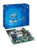
Desktop Board Features Desktop Board Components Figure 1 shows the approximate location of the major components on Intel Desktop Board DP43TF. Figure 1. Intel Desktop Board DP43TF Components 11 - Intel DP43TF | Product Guide - Page 12
fan header (3-pin) BIOS configuration jumper block IDE connector Serial header Serial ATA connectors (6) Front panel header Alternate front panel power LED header IEEE 1394a header HD audio link header High-speed USB 2.0 headers (3) Battery Speaker For more information about Intel Desktop Board - Intel DP43TF | Product Guide - Page 13
information about: • Instructions on installing or upgrading the processor, page 29 in Chapter 2 • Supported processors for Intel Desktop Board DP43TF, http://processormatch.intel.com Main Memory NOTE To be fully compliant with all applicable Intel ® SDRAM memory specifications, the board should be - Intel DP43TF | Product Guide - Page 14
, memory, PCI Express, and the DMI interconnect. The ICH10 is a centralized controller for the board's I/O paths. For more information on the Intel P43 Express Chipset go to http://developer.intel.com/products/chipsets/ Graphics Support The board supports an add-in PCI Express discrete graphics card - Intel DP43TF | Product Guide - Page 15
The onboard audio subsystem consists of the following: • Intel ICH10 I/O controller hub • RealTek ALC888VC audio codec • Intel High Definition Audio front panel audio header • Intel High Definition Audio Link header • Onboard 3-pin S/PDIF output connector The audio subsystem supports the following - Intel DP43TF | Product Guide - Page 16
between ICH10 and the LAN controller • PCI Express power management For information about LAN software and drivers go to http://support.intel.com/support/motherboards/desktop LAN Subsystem Software For LAN software and drivers, refer to the Intel Desktop Board DP43TF link on Intel's World Wide Web - Intel DP43TF | Product Guide - Page 17
LAN link is not established LAN link is established LAN activity is occurring 10 Mb/s data rate 100 Mb/s data rate 1000 Mb/s data rate Hi-Speed USB 2.0 Support The Desktop Board supports up to 12 USB 2.0 ports (six ports routed to the back panel and six ports routed to three internal headers - Intel DP43TF | Product Guide - Page 18
Intel Desktop Board DP43TF Product Guide BIOS The BIOS provides the Power-On Self-Test (POST), the BIOS Setup program, the PCI/PCI Express auto-configuration utilities, and the video BIOS. The BIOS is stored in the Serial Peripheral Interface (SPI) Flash device. The BIOS can be updated by following - Intel DP43TF | Product Guide - Page 19
board's fan speed, thermal, and voltage monitoring and control features include the following: • Monitoring of power supply voltages to detect levels above and below acceptable values • Intel Quiet System Technology fan speed control, delivering acoustically-optimized thermal management NOTE Memory - Intel DP43TF | Product Guide - Page 20
Intel Desktop Board DP43TF Product Guide Power Management Features Power management is implemented at several levels, including: • Software support through the Advanced Configuration and Power Interface (ACPI) • Hardware support: ⎯ Power connectors ⎯ Fan headers ⎯ LAN wake capabilities ⎯ Instantly - Intel DP43TF | Product Guide - Page 21
according to thermal conditions. • All fan headers have a +12 V DC connection. The Desktop Board has a 4-pin processor fan header, two 3-pin chassis fan headers, and one 4-pin chassis fan header. LAN Wake Capabilities CAUTION For LAN wake capabilities, the 5 V standby line for the power supply must - Intel DP43TF | Product Guide - Page 22
the memory module sockets and the PCI/PCI Express bus connectors. Figure 3. Location of the +5 V Standby Power Indicator For more information on standby current requirements for the Desktop Board, refer to the Technical Product Specification by going to http://support.intel.com/support/motherboards - Intel DP43TF | Product Guide - Page 23
is mounted on the Desktop Board. The speaker provides audible error code (beep code) information during the Power-On Self-Test (POST). Battery A battery on the Desktop Board keeps the values in CMOS RAM and the clock current when the computer is turned off. Go to page 53 for instructions on how to - Intel DP43TF | Product Guide - Page 24
Intel Desktop Board DP43TF Product Guide 24 - Intel DP43TF | Product Guide - Page 25
the Desktop Board • Install and remove a processor • Install and remove memory • Install and remove a PCI Express x16 card • Connect the IDE and Serial ATA cables • Connect to the internal headers • Connect to the onboard audio system • Connect chassis fan and power supply cables • Set the BIOS - Intel DP43TF | Product Guide - Page 26
Intel Desktop Board DP43TF Product Guide Installation Precautions When you install and test the Intel Desktop Board, observe all warnings and cautions in the installation instructions. To avoid injury, be careful of: • Sharp pins on connectors • Sharp pins on printed circuit assemblies • Rough edges - Intel DP43TF | Product Guide - Page 27
transmissions, protects internal components from dust and foreign objects, and promotes correct airflow within the chassis. Install the I/O shield before installing the Desktop Board in the chassis. Place the shield inside the chassis as shown in Figure 4. Press the shield into place so that it fits - Intel DP43TF | Product Guide - Page 28
can result in personal injury or equipment damage. Refer to your chassis manual for instructions on installing and removing the Desktop Board. Figure 5 shows the location of the mounting screw holes for Intel Desktop Board DP43TF. Figure 5. Intel Desktop Board DP43TF Mounting Screw Hole Locations 28 - Intel DP43TF | Product Guide - Page 29
the computer; the standby power LED should not be lit (see Figure 3 on page 22). Failure to do so could damage the processor and the board. To install a processor, follow these instructions: 1. Observe the precautions in "Before You Begin" on page 25. 2. Open the socket lever by pushing the lever - Intel DP43TF | Product Guide - Page 30
Intel Desktop Board DP43TF Product Guide 3. Lift the load plate (Figure 7, A). Do not touch the socket contacts (Figure 7, B). Figure 7. Lift the Load Plate 4. Remove the plastic protective socket cover from the load plate (Figure 8). Do not discard the protective socket cover. Always replace the - Intel DP43TF | Product Guide - Page 31
and Replacing Desktop Board Components 5. Remove the processor from the protective processor cover. Hold the processor only at the edges, being careful not to touch the bottom of the processor (see Figure 9). Do not discard the protective processor cover. Always replace the processor cover if - Intel DP43TF | Product Guide - Page 32
the socket lever (Figure 11, B). Figure 11. Close the Load Plate Installing a Processor Fan Heat Sink Intel Desktop Board DP43TF has mounting holes for a processor fan heat sink. For instructions on how to attach the processor fan heat sink to the Desktop Board, refer to the boxed processor manual - Intel DP43TF | Product Guide - Page 33
a 3-pin connector cannot use the onboard fan control, the fan will always operate at full speed. Figure 12. Connecting the Processor Fan Heat Sink Cable Removing the Processor For instructions on how to remove the processor fan heat sink and processor, refer to the processor installation manual. 33 - Intel DP43TF | Product Guide - Page 34
Intel Desktop Board DP43TF Product Guide Installing and Removing Memory Intel Desktop board DP43TF has four 240-pin DDR2 DIMM sockets arranged as DIMM 0 and DIMM 1 in both Channel A and Channel B. NOTE Regardless of the memory configuration used (dual or single channel), Channel A, DIMM 0 must - Intel DP43TF | Product Guide - Page 35
Installing and Replacing Desktop Board Components If additional memory is to be used, install another matched pair of DIMMs in DIMM 1 (black) in channels A and B (see Figure 14). Figure 14. Dual Channel Memory Configuration with Four DIMMs Three DIMMs If you want to use three DIMMs in a dual-channel - Intel DP43TF | Product Guide - Page 36
Intel Desktop Board DP43TF Product Guide Installing DIMMs To make sure you have the correct DIMM, place it on the illustration of the DDR2 DIMM in Figure 16. All the notches should match with the DDR2 DIMM. Figure 16. Use DDR2 DIMMs 36 - Intel DP43TF | Product Guide - Page 37
Installing and Replacing Desktop Board Components To install a DIMM, follow these steps: 1. Observe the precautions in "Before You Begin" on page 25. 2. Turn off all peripheral devices connected to the computer. Turn off the computer and disconnect the AC power cord. 3. Remove the computer's cover - Intel DP43TF | Product Guide - Page 38
Desktop Board DP43TF Product Guide 7. Insert the bottom edge of the DIMM into the socket. 8. When the DIMM is inserted, push down on the top edge of the DIMM until the retaining clips snap into place. Make sure the clips are firmly in place. 9. Replace the computer's cover and reconnect the AC power - Intel DP43TF | Product Guide - Page 39
Desktop Board Components Installing a PCI Express x16 Card 1. Observe the precautions in "Before You Begin" on page 25. 2. Place the card in the PCI Express x16 connector (Figure 18, A) and press down on the card until it is completely seated in the connector and the card retention notch on the card - Intel DP43TF | Product Guide - Page 40
Intel Desktop Board DP43TF Product Guide Removing the PCI Express x16 Card Follow these instructions to remove the PCI Express x16 card from the connector: 1. Observe the precautions in "Before You Begin" on page 25. 2. Remove the screw (Figure 19, A) that secures the card's metal bracket to the - Intel DP43TF | Product Guide - Page 41
be used to connect two IDE drives to the Desktop Board. The cable supports the ATA-66/100 transfer protocol. Figure 20 shows on page 25. • Attach the cable end with the single connector (blue) to the Intel Desktop Board (Figure 20, A). • Attach the cable end with the two closely spaced connectors ( - Intel DP43TF | Product Guide - Page 42
Intel Desktop Board DP43TF Product Guide Figure 20. Connecting the IDE Cable 42 - Intel DP43TF | Product Guide - Page 43
Components Connecting Serial ATA (SATA) Cables SATA cables support the Serial ATA protocol. Each cable can be used to connect a single SATA drive to the Desktop Board. For correct cable function: 1. Observe the precautions in "Before You Begin" on page 25. 2. Attach one end the SATA cable to one - Intel DP43TF | Product Guide - Page 44
Begin" on page 25. Figure 22 shows the location of the internal headers and connectors. Item Description A HD Audio Link B S/PDIF C Chassis intrusion D Audio E USB 2.0 (3) Item Description F Serial G Front panel H Alternate front panel power LED I IEEE 1394a Figure 22. Internal - Intel DP43TF | Product Guide - Page 45
Installing and Replacing Desktop Board Components HD Audio Link Header See Figure 22, A for the location of the HD Audio Link header. Table 5 shows the pin assignments for the header. Table 5. HD Audio Link Header Signal Names Pin Signal Name 1 BCLK 3 RST# Pin Signal Name 2 Ground 4 - Intel DP43TF | Product Guide - Page 46
Intel Desktop Board DP43TF Product Guide Front Panel HD Audio Header Figure 22, D shows the location of the front panel audio header. Table 8 shows the pin assignments for the front panel audio header. Table 8. Front Panel Audio Header Signal Names Pin Signal Name 1 PORT 1L 3 PORT 1R 5 - Intel DP43TF | Product Guide - Page 47
4 Front panel yellow LED Reset Switch On/Off Switch 5 Ground 6 Power switch 7 Reset switch In 8 Ground Power Not Connected 9 Power Out 10 No pin In/Out Out Out In Alternate Front Panel Power LED Header Figure 22, H shows the location of the alternate front panel power LED header. Pins - Intel DP43TF | Product Guide - Page 48
Intel Desktop Board DP43TF Product Guide IEEE 1394a Header See Figure 22, I for the location of the IEEE 1394a header. Table 13 shows the pin assignments for the header. Table 13. IEEE 1394a Header Signal Names Pin Signal Name 1 TPA1+ 3 Ground 5 TPA2+ 7 +12 V 9 Key (no pin) Pin - Intel DP43TF | Product Guide - Page 49
Replacing Desktop Board Components Connecting Chassis Fan and Power Supply Cables Chassis Fan Cables Connect chassis fan cables to the 3-pin and 4-pin chassis fan headers on the Desktop Board. Figure 24 shows the location of the chassis fan headers. Figure 24. Location of the Chassis Fan Headers 49 - Intel DP43TF | Product Guide - Page 50
Intel Desktop Board DP43TF Product Guide Power Supply Cables CAUTION Failure to use an appropriate power supply and/or not connecting the 12 V (2 x 2 pin) power connector to the Desktop Board may result in damage to the board or the system may not function properly. The 2 x 12 pin main power - Intel DP43TF | Product Guide - Page 51
Desktop Board Components Setting the BIOS Configuration Jumper NOTE Always turn off the power and unplug the power cord from the computer before moving the jumper. Moving the jumper with the power on may result in unreliable computer operation. Figure 26 shows the location of the Desktop Board - Intel DP43TF | Product Guide - Page 52
Intel Desktop Board DP43TF Product Guide Table 14. Jumper Settings for the BIOS Setup Program Modes Jumper Setting Mode Normal (default) (1-2) Description The BIOS uses the current configuration and passwords for booting. Configure (2-3) After the Power-On Self-Test (POST) runs, the BIOS - Intel DP43TF | Product Guide - Page 53
, and turn on the computer. Replacing the Battery A coin-cell battery (CR2032) powers the real-time clock and CMOS memory. When the computer is not plugged into a wall socket, the battery has an estimated life of three years. When the computer is plugged in, the standby current from the power supply - Intel DP43TF | Product Guide - Page 54
Intel Desktop Board DP43TF Product Guide VIKTIGT! Risk för explosion om batteriet ersätts med felaktig batterityp. Batterier ska kasseras enligt de lokala miljövårdsbestämmelserna. VARO Räjähdysvaara, jos pariston tyyppi on väärä. - Intel DP43TF | Product Guide - Page 55
Installing and Replacing Desktop Board Components UPOZORNÌNÍ V případě výměny baterie za nesprávný druh může dojít k výbuchu. Je-li to možné, baterie by měly být recyklovány. Baterie je třeba zlikvidovat v souladu s mí - Intel DP43TF | Product Guide - Page 56
Intel Desktop Board DP43TF Product Guide UPOZORNENIE Ak batériu vymeníte za nesprávny typ, hrozí nebezpečenstvo jej výbuchu. Batérie by sa mali podľa možnosti vždy recyklovať. - Intel DP43TF | Product Guide - Page 57
Installing and Replacing Desktop Board Components 57 - Intel DP43TF | Product Guide - Page 58
Intel Desktop Board DP43TF Product Guide To replace the battery, follow these steps: 1. Observe the precautions in "Before You Begin" (see page 25). 2. Turn off all peripheral devices connected to the computer. Disconnect the computer's power cord from the AC power source (wall outlet or power - Intel DP43TF | Product Guide - Page 59
: http://support.intel.com/support/motherboards/desktop/ 2. Navigate to the Intel Desktop Board DP43TF page. Under the "Software and drivers" heading, click on "Latest BIOS" to locate the latest BIOS files. Click on the "BIOS Update" link and select the Express BIOS Update file. 3. Download the file - Intel DP43TF | Product Guide - Page 60
support/motherboards/desktop. Navigate to the Intel Desktop Board DP43TF page. Under the "Software and drivers" heading, click on "Latest BIOS" to locate the latest BIOS files. Click on the "BIOS Update" link and select the ISO Image BIOS Update file or the Iflash BIOS Update file. Updating the BIOS - Intel DP43TF | Product Guide - Page 61
Intel Desktop Board BIOS Upgrade CD-ROM" page, press any key to confirm the BIOS upgrade operation. 6. Wait for the BIOS upgrade process to complete. CAUTION DO NOT POWER DOWN YOUR COMPUTER before the update is complete. The update may take up to 5 minutes. Updating the BIOS with the Iflash Memory - Intel DP43TF | Product Guide - Page 62
Intel Desktop Board DP43TF Product Guide CAUTION Do not interrupt the process or the system may not function properly. 1. Uncompress the BIOS update file and copy the .BIO file, IFLASH.EXE, and .ITK file (optional) to a bootable USB flash drive or other bootable USB media. 2. Configure the BIOS or - Intel DP43TF | Product Guide - Page 63
Desktop Board DP43TF reports POST errors in two ways: • By sounding a beep code • By displaying an error message on the monitor BIOS Beep Codes The BIOS also issues a beep code (one long tone followed by two short tones) during POST if the video configuration fails (a faulty video card or no card - Intel DP43TF | Product Guide - Page 64
Intel Desktop Board DP43TF Product Guide 64 - Intel DP43TF | Product Guide - Page 65
(EMC) regulations • Product certifications Safety Standards Intel Desktop Board DP43TF complies with the safety standards stated in Table Place Battery Marking There is insufficient space on this Desktop Board to provide instructions for replacing and disposing of the Lithium ion coin cell - Intel DP43TF | Product Guide - Page 66
Intel Desktop Board DP43TF Product Guide European Union Declaration of Conformity Statement We, Intel Corporation, declare under our sole responsibility that the product Intel® Desktop Board DP43TF is in conformity with all applicable essential requirements necessary for CE marking, following the - Intel DP43TF | Product Guide - Page 67
. Please consult http://intel.com/intel/other/ehs/product_ecology for the details of this program, including the scope of covered products, available locations, shipping instructions, terms and conditions, etc Intel Product Recycling Program http://intel.com/intel/other/ehs/product_ecology 67 - Intel DP43TF | Product Guide - Page 68
Intel Desktop Board DP43TF Product Guide Deutsch Als Teil von Intels Engagement für den Umweltschutz hat das Unternehmen das Intel Produkt-Recyclingprogramm implementiert, das Einzelhandelskunden von Intel , les instructions d'expédition, les conditions générales, etc. http://intel.com/intel/ot her - Intel DP43TF | Product Guide - Page 69
dos produtos cobertos, os locais disponíveis, as instruções de envio, os termos e condições, etc. Russian Intel Intel (Product Recycling Program Intel http://intel.com/intel/other/ehs/product_ecology Türkçe Intel, çevre sorumluluğuna bağımlılığının bir parçası olarak, perakende tüketicilerin - Intel DP43TF | Product Guide - Page 70
Intel Desktop Board DP43TF Product Guide Lead-free 2LI/Pb-free 2LI Board The electronics industry is acceptable because of the RoHS "flip chip" or "die bump" interconnect exemption. Intel Desktop Board DP43TF is a lead-free second level interconnect product. Table 18 shows the lead-free - Intel DP43TF | Product Guide - Page 71
components in which the Pb concentration level in the Desktop Board substrate and the solder connections from the board to or the components (second-level interconnect) is 0.01% or 100 ppm) by weight of homogeneous material. Intel Desktop Board DP43TF complies with these restrictions. 71 - Intel DP43TF | Product Guide - Page 72
and has the same limits as EU RoHS. However, the China RoHS regulation requires specific product marking and a selfdeclaration of the controlled substances contained in each product. Intel Desktop Board DP43TF is a China RoHS-compliant product. The required China RoHS mark indicates the product - Intel DP43TF | Product Guide - Page 73
Regulatory Compliance The China MII stipulates that a material Self Declaration Table (SDT) must be included in a product's user documentation. The SDT for Intel Desktop Board DP43TF is shown in Figure 28. Figure 28. Intel Desktop Board DP43TF China RoHS Material Self Declaration Table 73 - Intel DP43TF | Product Guide - Page 74
Intel Desktop Board DP43TF Product Guide EMC Regulations Intel Desktop Board DP43TF complies with the EMC regulations stated in Table 20 when correctly installed in a compatible host system. Table 20. EMC Regulations Regulation (Class B) FCC 47 CFR Part 15, Subpart B ICES-003 Issue 4 EN55022: - Intel DP43TF | Product Guide - Page 75
Class B EMC testing and are marked accordingly. Pay close attention to the following when reading the installation instructions for the host chassis, power supply, and other modules: • Product certifications or lack of certifications • External I/O cable shielding and filtering • Mounting, grounding - Intel DP43TF | Product Guide - Page 76
(NZ RSM) C-tick mark. Includes adjacent Intel supplier code number, N-232. Japan VCCI (Voluntary Control Council for Interference) mark. S. Korea MIC (Ministry of Information and Communication) mark. Includes adjacent MIC certification number: CPU-DP43TF (B). Taiwan BSMI (Bureau of Standards - Intel DP43TF | Product Guide - Page 77
Certifications Ensure that the chassis and certain components; such as the power supply, peripheral drives, wiring, and cables; are components certified for the requirements. The Industry Canada statement at the front of this product guide demonstrates compliance with Canadian EMC regulations. 77 - Intel DP43TF | Product Guide - Page 78
Intel Desktop Board DP43TF Product Guide 78
-
 1
1 -
 2
2 -
 3
3 -
 4
4 -
 5
5 -
 6
6 -
 7
7 -
8
-
9
-
10
-
11
-
12
-
13
-
14
-
15
-
16
-
17
-
18
-
19
-
20
-
21
-
22
-
23
-
24
-
25
-
26
-
27
-
28
-
29
-
30
-
31
-
32
-
33
-
34
-
35
-
36
-
37
-
38
-
39
-
40
-
41
-
42
-
43
-
44
-
45
-
46
-
47
-
48
-
49
-
50
-
51
-
52
-
53
-
54
-
55
-
56
-
57
-
58
-
59
-
60
-
61
-
62
-
63
-
64
-
65
-
66
-
67
-
68
-
69
-
70
-
71
-
72
-
73
-
74
-
75
-
76
-
77
-
78
 |
 |

Intel
®
Desktop Board DP43TF
Product Guide
Order Number:
E4079
8
-001