Intel DP45SG Product Guide
Intel DP45SG - Desktop Board Extreme Series Motherboard Manual
 |
UPC - 675900939738
View all Intel DP45SG manuals
Add to My Manuals
Save this manual to your list of manuals |
Intel DP45SG manual content summary:
- Intel DP45SG | Product Guide - Page 1
Intel® Desktop Board DP45SG Product Guide Order Number: E30016-001 - Intel DP45SG | Product Guide - Page 2
Intel® Desktop Board DP45SG Product Guide Date June 2008 If an FCC declaration of conformity marking is present on the board instructions, Intel may make changes to specifications and product descriptions at any time, without notice. Intel Desktop Board DP45SG may contain design defects or errors - Intel DP45SG | Product Guide - Page 3
summary of product features 2 Installing and Replacing Desktop Board Components: instructions on how to install the Desktop Board and other hardware components 3 Updating the BIOS: instructions on how to update the BIOS 4 Configuring for RAID Using Intel® Matrix Storage Technology: information about - Intel DP45SG | Product Guide - Page 4
Intel Desktop Board DP45SG Product Guide Conventions The following conventions are used in this manual: CAUTION Cautions warn the user about how to prevent damage to hardware or loss of data. NOTE Notes call attention to important information. Terminology The - Intel DP45SG | Product Guide - Page 5
Board Features Desktop Board Components 11 Processor ...13 Main Memory...13 Intel® P45 Express Chipset 14 Audio Subsystem 14 LAN Subsystem 15 USB 2.0 Support 16 Serial ATA Support 16 Serial ATA RAID 16 Intel® Rapid Recover Technology (Intel® RRT 16 Legacy I/O ...17 Expandability...17 BIOS - Intel DP45SG | Product Guide - Page 6
Intel Desktop Board DP45SG Product Guide Installing and Removing a Processor 29 Installing a Processor 29 Installing the Processor Fan Heat Sink 33 Connecting the Processor Fan Heat Sink Cable 33 Removing the - Intel DP45SG | Product Guide - Page 7
67 Creating a Recovery Volume 68 Creating a Recovery Volume Using the RAID Option ROM 68 Creating a Recovery Volume Using the Intel® Matrix Storage Console 68 Disk Synchronization Mode 69 Mounting the Recovery Disk 69 A Error Messages and Indicators BIOS Beep Codes 71 BIOS Error Messages 71 - Intel DP45SG | Product Guide - Page 8
BIOS Configuration Jumper Block 53 28. Removing the Battery 60 29. Intel Desktop Board DP45SG China RoHS Material Self Declaration Table 81 Tables 1. Feature Summary 9 2. Intel Desktop Board DP45SG Components 12 3. LAN Connector LEDs 15 4. S/PDIF Connector Signal Names 45 5. Front Panel Audio - Intel DP45SG | Product Guide - Page 9
briefly describes the features of Intel® Desktop Board DP45SG. Table 1 summarizes the major features of the Desktop Board. Table 1. Feature Summary Form Factor Processor Main Memory Chipset Graphics Audio Expansion Capabilities Legacy I/O Support Peripheral Interfaces ATX (294.64 millimeters [11 - Intel DP45SG | Product Guide - Page 10
XP Professional • Microsoft Windows XP Professional x64 Edition • Microsoft Windows XP Home For more information about Intel Desktop Board DP45SG, including the Technical Product Specification (TPS), BIOS updates, and device drivers, go to http://support.intel.com/support/motherboards/desktop/. 10 - Intel DP45SG | Product Guide - Page 11
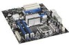
Desktop Board Features Desktop Board Components Figure 1 shows the approximate location of the major components on Intel Desktop Board DP45SG. Figure 1. Intel Desktop Board DP45SG Components 11 - Intel DP45SG | Product Guide - Page 12
Intel Desktop Board DP45SG Product Guide Table 2. Intel Desktop Board DP45SG Components Label A B C D E F G H I J K L M N O P Q R S T U V W X Y Z AA BB socket DDR3 DIMM 0 sockets DDR3 DIMM 1 sockets Main power connector (2 x 12 pin) Front chassis fan header (3-pin) Chassis intrusion header BIOS - Intel DP45SG | Product Guide - Page 13
connects to the Desktop Board through the LGA775 socket. Go to the following locations for more information about: • Instructions on installing or upgrading the processor, page 29 in Chapter 2 • Supported processors for Intel Desktop Board DP45SG, http://processormatch.intel.com Main Memory NOTE To - Intel DP45SG | Product Guide - Page 14
Intel Desktop Board DP45SG Product Guide Go to the following locations for more information about: • SDRAM specifications, http://www.intel.com/technology/memory/ • Installing memory, page 35 in Chapter 2 • Tested memory, http://www.cmtlabs.com/mbsearch.asp Intel® P45 Express Chipset The Intel P45 - Intel DP45SG | Product Guide - Page 15
• LAN connect interface between ICH10R and the LAN controller • PCI Express power management For information about LAN software and drivers go to http://support.intel.com/support/motherboards/desktop Two LEDs are built into the RJ-45 LAN connector located on the back panel (see Figure 2). These LEDs - Intel DP45SG | Product Guide - Page 16
system and drivers that fully support USB 2.0 transfer rates. Disabling Hi-Speed USB in the BIOS reverts all USB 2.0 ports to USB 1.1 operation. This may be required to accommodate operating systems that do not support USB 2.0. Serial ATA Support Intel Desktop Board DP45SG supports five onboard - Intel DP45SG | Product Guide - Page 17
support Expandability Intel Desktop Board DP45SG provides the following expansion capability: • Two PCI Express 2.0 x16 connectors (compatible with PCI Express 1.1 add-in cards) • Two PCI Express 1.1 x1 connectors • Three PCI bus connectors BIOS The BIOS provides the Power-On Self-Test (POST - Intel DP45SG | Product Guide - Page 18
. Related Links: For instructions on resetting the password, go to Clearing Passwords on page 54. Hardware Management The hardware management features of Intel Desktop Board DP45SG enable the board to be compatible with the Wired for Management (WfM) specification. The board has several hardware - Intel DP45SG | Product Guide - Page 19
support: • Power connectors • Fan headers • LAN wake capabilities • Instantly Available PC technology (Suspend to RAM Desktop Board requires an operating system that provides full ACPI support. Hardware Support in the BIOS Setup program's Boot menu. The Desktop Board has three power connectors. - Intel DP45SG | Product Guide - Page 20
Intel Desktop Board DP45SG Product Guide Fan Headers The function/operation of the fans is as support multiple wake events from the PCI and/or USB buses exceeds power supply capacity, the Desktop Board may lose register settings stored in memory. Instantly Available PC technology enables the board - Intel DP45SG | Product Guide - Page 21
For more information on standby current requirements for the Desktop Board, refer to the Technical Product Specification by going to the following link, finding the product, and selecting Product Documentation from the left-hand menu: http://support.intel.com/support/motherboards/desktop/ 21 - Intel DP45SG | Product Guide - Page 22
audible error code (beep code) information during the Power-On Self-Test (POST). Refer to Appendix A for a description of the board's beep codes. Battery A battery on the Desktop Board keeps the values in CMOS RAM and the clock current when the computer is turned off. Go to page 55 for instructions - Intel DP45SG | Product Guide - Page 23
Desktop Board Features Real-Time Clock The Desktop Board has a time-of-day clock and 100-year calendar. The battery on the Desktop Board keeps the clock current when the computer is turned off. 23 - Intel DP45SG | Product Guide - Page 24
Intel Desktop Board DP45SG Product Guide 24 - Intel DP45SG | Product Guide - Page 25
and remove the Desktop Board • Install and remove a processor • Install the ICH heat sink decorative cover (optional) • Install and remove memory • Install and remove PCI Express x16 cards • Connect the Serial ATA cables • Connect to the internal headers and connectors • Connect to the audio system - Intel DP45SG | Product Guide - Page 26
Intel Desktop Board DP45SG Product Guide Installation Precautions When you install and test the Intel Desktop Board, observe all warnings and cautions in the installation instructions all warnings and cautions that instruct you to refer computer servicing to qualified technical personnel. Prevent - Intel DP45SG | Product Guide - Page 27
components from dust and foreign objects, and promotes correct airflow within the chassis. Install the I/O shield before installing the Desktop Board in the chassis. Place the shield inside the chassis as shown in Figure 4. Press the shield into place so that it fits tightly and securely. If the - Intel DP45SG | Product Guide - Page 28
Intel Desktop Board DP45SG Product Guide Installing and Removing the Desktop Board CAUTION Only qualified manual for instructions on installing and removing the Desktop Board. Figure 5 shows the location of the mounting screw holes for Intel Desktop Board DP45SG. Figure 5. Intel Desktop Board DP45SG - Intel DP45SG | Product Guide - Page 29
Desktop Board Components Installing and Removing a Processor Instructions on how to install the processor on the Desktop Board processor and the board. To install a processor, follow these instructions: 1. Observe the precautions in "Before You Begin" on page 25. 2. Open the socket lever by pushing - Intel DP45SG | Product Guide - Page 30
Intel Desktop Board DP45SG Product Guide 3. Lift the load plate (Figure 7, A). Do not touch the socket contacts (Figure 7, B). Figure 7. Lift the Load Plate 4. Remove the plastic protective socket cover from the load plate (Figure 8). Do not discard the protective socket cover. Always replace the - Intel DP45SG | Product Guide - Page 31
Installing and Replacing Desktop Board Components 5. Remove the processor from the protective processor protective processor cover. Always replace the processor cover if the processor is removed from the socket. Figure 9. Remove the Processor from the Protective Processor Cover 6. Hold the processor - Intel DP45SG | Product Guide - Page 32
Intel Desktop Board DP45SG Product Guide 7. Pressing down on the load plate (Figure 11, A), close and engage the socket lever (Figure 11, B). Figure 11. Close the Load Plate 32 - Intel DP45SG | Product Guide - Page 33
Components Installing the Processor Fan Heat Sink Intel Desktop Board DP45SG has mounting holes for a processor fan heat sink. For instructions on how to attach the processor fan heat sink to the Desktop Board, refer to the boxed processor manual. Connecting the Processor Fan Heat Sink Cable Connect - Intel DP45SG | Product Guide - Page 34
Intel Desktop Board DP45SG Product Guide Removing the Processor For instructions on how to remove the processor fan heat sink and processor, refer to the processor installation manual. Installing the ICH Heat Sink Decorative Cover (Optional) To install the ICH heat sink decorative cover, follow - Intel DP45SG | Product Guide - Page 35
NOTE To be fully compliant with all applicable Intel SDRAM memory specifications, the board requires DIMMs that support the Serial Presence Detect (SPD) data structure. Intel Desktop board DP45SG has four 240-pin DDR3 DIMM sockets arranged as DIMM 0 and DIMM 1 in both Channel A and Channel B. NOTE - Intel DP45SG | Product Guide - Page 36
Intel Desktop Board DP45SG Product Guide If additional memory is to be used, install another matched pair of DIMMs in DIMM 1 (black) in channels A and B (see Figure 15). Figure 15. Dual Channel Memory Configuration with Four DIMMs Three DIMMs If you want to use three DIMMs in a dual-channel - Intel DP45SG | Product Guide - Page 37
Installing and Replacing Desktop Board Components Installing DIMMs To make sure you have the correct DIMM, place it on the illustration of the DDR3 DIMM in Figure 17. All the notches should match with the DDR3 DIMM. Figure 17. Use DDR3 DIMMs 37 - Intel DP45SG | Product Guide - Page 38
Intel Desktop Board DP45SG Product Guide To install a DIMM, follow these steps: 1. Observe the Remove the computer's cover and locate the DIMM sockets (see Figure 18). Figure 18. Installing a DIMM 4. Make sure the clips at either end of the DIMM socket(s) are pushed outward to the open position. - Intel DP45SG | Product Guide - Page 39
Installing and Replacing Desktop Board Components Removing DIMMs To remove a DIMM, follow these steps: 1. spread the retaining clips at each end of the DIMM socket. The DIMM pops out of the socket. 6. Hold the DIMM by the edges, lift it away from the socket, and store it in an anti-static package. - Intel DP45SG | Product Guide - Page 40
Intel Desktop Board DP45SG Product Guide Installing and Removing a PCI Express x16 Card CAUTION When installing a PCI Express card on the Desktop Board, on the over-current protection of the power supply, certain Desktop Board components and/or traces may be damaged. Installing Multiple PCI - Intel DP45SG | Product Guide - Page 41
Installing and Replacing Desktop Board Components Installing a PCI Express x16 Card Follow these instructions to install any PCI Express x16 card: 1. Observe the precautions in "Before You Begin" on page 25. 2. Place the card in a PCI Express x16 connector ( - Intel DP45SG | Product Guide - Page 42
Intel Desktop Board DP45SG Product Guide Removing a PCI Express x16 Card Follow these instructions to remove a PCI Express x16 card from a connector: 1. Observe the precautions in "Before You Begin" on page 25. 2. Remove the screw (Figure 21, A) that secures - Intel DP45SG | Product Guide - Page 43
Components Connecting the Serial ATA (SATA) Cables SATA cables support the Serial ATA protocol. Each cable can be used to connect one internal SATA drive to the Desktop Board. For correct cable function: 1. Observe the precaution in "Before You Begin" on page 25. 2. Attach one end of the SATA cable - Intel DP45SG | Product Guide - Page 44
You Begin" on page 25. Figure 23 shows the location of the internal headers and connectors on Intel Desktop Board DP45SG. Item Description A S/PDIF B Front panel audio C IEEE 1394a D Back panel CIR emitter (output) E Front panel CIR receiver (input) F Chassis intrusion Item Description - Intel DP45SG | Product Guide - Page 45
Installing and Replacing Desktop Board Components S/PDIF Connector Figure 23, A shows the location of the S/PDIF connector. This connector can be used with HDMI video cards that do not work with the HD Audio Link header (see Figure 23, B). Table 4 shows the pin assignments and signal names for the - Intel DP45SG | Product Guide - Page 46
Intel Desktop Board DP45SG Product Guide IEEE 1394a Header Figure 23, C shows the location of the NOTE The Consumer IR option must be enabled in the system BIOS before it can function. Press at boot to enter the system BIOS, and go to Advanced > Peripheral Configuration > Enhanced Consumer IR - Intel DP45SG | Product Guide - Page 47
Installing and Replacing Desktop Board Components Table 9. Back Panel CIR Header Emitter (Output) Header Signal Names Pin Signal Name 1 Emitter Out 1 3 Ground 5 Jack Detect 1 Pin Signal Name 2 Emitter Out 2 4 Key ( - Intel DP45SG | Product Guide - Page 48
Intel Desktop Board DP45SG Product Guide Alternate Front Panel Power LED Header Figure 23, G shows the No pin 3 Front panel yellow LED In/Out Out Out HD Audio Link Header Figure 23, I shows the location of the HD Audio Link header. Table 13 shows the pin assignments and signal names for the - Intel DP45SG | Product Guide - Page 49
Installing and Replacing Desktop Board Components USB 2.0 Headers Figure 23, J shows the location requirements, even if no device or a low-speed USB device is attached to the cable. Use a shielded cable that meets the requirements for a full-speed USB device. Serial Port Header See Figure 23, E - Intel DP45SG | Product Guide - Page 50
Intel Desktop Board DP45SG Product Guide Connecting to the Flexible Audio System After installing the IDT* audio driver from the Intel® Express Installer DVD-ROM, the multi-channel audio feature can be enabled. Figure 24 shows the back panel audio connectors. The default connector assignments are - Intel DP45SG | Product Guide - Page 51
Installing and Replacing Desktop Board Components Connecting Chassis Fan and Power Supply Cables Connecting Chassis Fan Cables Connect chassis fan cables to the 3-pin and 4-pin chassis fan headers on the Desktop Board. Figure 25 shows the location of the chassis fan headers. Figure 25. Location of - Intel DP45SG | Product Guide - Page 52
Intel Desktop Board DP45SG Product Guide Connecting Power Supply Cables CAUTION Failure to use an appropriate power supply and/or not connecting the 12 V (2 x 2 pin) power connector to the Desktop Board may result in damage to the board or the system may not function properly. The 2 x 12 pin main - Intel DP45SG | Product Guide - Page 53
operation. Figure 27 shows the location of the Desktop Board's BIOS configuration jumper block. Figure 27. Location of the BIOS Configuration Jumper Block The three-pin BIOS jumper block enables all board configurations to be done in the BIOS Setup program. Table 16 shows the jumper settings - Intel DP45SG | Product Guide - Page 54
Intel Desktop Board DP45SG Product Guide Table 16. Jumper Settings for the BIOS Setup Program Modes Jumper Setting Mode Normal (default) (1-2) Description The BIOS uses the current configuration and passwords for booting. Configure (2-3) After the Power-On Self-Test (POST) runs, the BIOS - Intel DP45SG | Product Guide - Page 55
Desktop Board powers the real-time clock and CMOS memory. When the computer is not plugged into a wall socket, the battery has an estimated life of . When the voltage drops below a certain level, the BIOS Setup program settings stored in CMOS RAM (for example, the date and time) might not be - Intel DP45SG | Product Guide - Page 56
Intel Desktop Board DP45SG Product Guide VIKTIGT! Risk för explosion om batteriet ersätts med felaktig batterityp. Batterier ska kasseras enligt de lokala miljövårdsbestämmelserna. VARO Räjähdysvaara, jos pariston tyyppi on väärä. - Intel DP45SG | Product Guide - Page 57
Installing and Replacing Desktop Board Components UPOZORNÌNÍ V případě výměny baterie za nesprávný druh může dojít k výbuchu. Je-li to možné, baterie by měly být recyklovány. Baterie je třeba zlikvidovat v souladu s mí - Intel DP45SG | Product Guide - Page 58
Intel Desktop Board DP45SG Product Guide UPOZORNENIE Ak batériu vymeníte za nesprávny typ, hrozí nebezpečenstvo jej výbuchu. Batérie by sa mali podľa možnosti vždy recyklovať. - Intel DP45SG | Product Guide - Page 59
Installing and Replacing Desktop Board Components 59 - Intel DP45SG | Product Guide - Page 60
Intel Desktop Board DP45SG Product Guide To replace the battery, follow these steps: 1. Observe the source (wall outlet or power adapter). 3. Remove the computer cover. 4. Locate the battery on the board (see Figure 28). 5. With a medium flat-bladed screwdriver, gently pry the battery free from its - Intel DP45SG | Product Guide - Page 61
the BIOS with the Intel Express BIOS Update utility: 1. Go to the Intel World Wide Web site: http://support.intel.com/support/motherboards/desktop/ 2. Navigate to the Intel Desktop Board DP45SG page, click "[view] Latest BIOS updates," and select the Express BIOS Update utility file. 3. Download the - Intel DP45SG | Product Guide - Page 62
Intel Desktop Board DP45SG page on the Intel World Wide Web site at: http://support.intel.com/support/motherboards/desktop Navigate to the Intel Desktop Board DP45SG page, click "[view] Latest BIOS updates," and select the ISO Image BIOS Update or Iflash BIOS Update utility file. Updating the BIOS - Intel DP45SG | Product Guide - Page 63
Intel Desktop Board BIOS Upgrade CD-ROM" page, press any key to confirm the BIOS upgrade operation. 6. Wait for the BIOS upgrade process to complete. CAUTION DO NOT POWER DOWN YOUR COMPUTER before the update is complete. The update may take up to 5 minutes. Updating the BIOS with the Iflash Memory - Intel DP45SG | Product Guide - Page 64
damaged. Due to BIOS size and recovery requirements, a CD-R with the .BIO file in the root directory will be required. For more information about updating the Intel Desktop Board BIOS or recovering from a BIOS update failure, go to http://support.intel.com/support/motherboards/desktop/sb/CS-022312 - Intel DP45SG | Product Guide - Page 65
two or more SATA hard drives to the SATA connectors. 2. Enter system BIOS Setup by pressing after the Power-On-Self-Test (POST) memory tests begin. 3. Go to Advanced Drive Configuration Configure SATA as; ensure that RAID is selected. 4. Then save your settings by pressing . Creating Your - Intel DP45SG | Product Guide - Page 66
the Intel Express Installer Driver and Softwared DVD included with your Desktop Board or after downloading it from the Internet at http://support.intel.com/support/motherboards/desktop/. The Intel Matrix Storage Console software can be used to manage the RAID configuration. Setting Up a "RAID Ready - Intel DP45SG | Product Guide - Page 67
Rapid Recover Technology does not support RAID 5. Intel Rapid Recover Technology can be Enabled or Disabled in the system BIOS menu. To enable Intel Rapid Recover Technology, complete following steps: 1. Enter the BIOS menu by pressing the key early during system POST. 2. Go to Advanced Drive - Intel DP45SG | Product Guide - Page 68
Intel Desktop Board DP45SG Product Guide Creating a Recovery Volume A recovery volume consists of two disks - a master disk and a recovery disk. A recovery volume can be created with either the RAID Option ROM (OROM) or the Intel® Matrix Storage Console application. Creating a Recovery Volume Using - Intel DP45SG | Product Guide - Page 69
volume. Disk Synchronization Mode There are two modes of updating or synchronizing the recovery disk with the master disk - either continuous update or manual update. To change from Continuous Update mode to Update On Request mode using the Intel Matrix Storage Console, select the Advanced mode from - Intel DP45SG | Product Guide - Page 70
Intel Desktop Board DP45SG Product Guide To un-mount the recovery disk, complete the following steps: 1. In the Advanced mode, right-click on the recovery volume name. 2. Select Access Recovery Drive Files. 3. Select OK on the information dialog box. The recovery disk is now un-mounted and reappears - Intel DP45SG | Product Guide - Page 71
Messages and Indicators Intel Desktop Board DP45SG reports POST errors in two ways: • By sounding a beep code • By displaying an error message on the monitor BIOS Beep Codes The BIOS also issues a beep code (one long tone followed by two short tones) during POST if the video configuration fails - Intel DP45SG | Product Guide - Page 72
Intel Desktop Board DP45SG Product Guide 72 - Intel DP45SG | Product Guide - Page 73
(EMC) regulations • Product certifications Safety Standards Intel Desktop Board DP45SG complies with the safety standards stated in Table Place Battery Marking There is insufficient space on this Desktop Board to provide instructions for replacing and disposing of the Lithium ion coin cell - Intel DP45SG | Product Guide - Page 74
Intel Desktop Board DP45SG Product Guide European Union Declaration of Conformity Statement We, Intel Corporation, declare under our sole responsibility that the product Intel® Desktop Board DP45SG is in conformity with all applicable essential requirements necessary for CE marking, following the - Intel DP45SG | Product Guide - Page 75
consult http://www.intel.com/intel/other/ehs/product_ecology for the details of this program, including the scope of covered products, available locations, shipping instructions, terms and conditions, etc Intel Product Recycling Program http://www.intel.com/intel/other/ehs/product_ecology 75 - Intel DP45SG | Product Guide - Page 76
Intel Desktop Board DP45SG Product Guide Deutsch Als Teil von Intels Engagement für den Umweltschutz hat das Unternehmen das Intel Produkt-Recyclingprogramm implementiert, das Einzelhandelskunden von Intel , les instructions d'expédition, les conditions générales, etc. http://www.intel.com/in - Intel DP45SG | Product Guide - Page 77
produtos cobertos, os locais disponíveis, as instruções de envio, os termos e condições, etc. Russian Intel Intel (Product Recycling Program Intel http://www.intel.com/intel/other/ehs/product_ecology Türkçe Intel, çevre sorumluluğuna bağımlılığının bir parçası olarak, perakende tüketicilerin - Intel DP45SG | Product Guide - Page 78
Intel Desktop Board DP45SG Product Guide Lead-free 2LI/Pb-free 2LI Board The electronics industry is acceptable because of the RoHS "flip chip" or "die bump" interconnect exemption. Intel Desktop Board DP45SG is a lead-free second level interconnect product. Table 20 shows the lead-free - Intel DP45SG | Product Guide - Page 79
components in which the Pb concentration level in the Desktop Board substrate and the solder connections from the board to or the components (second-level interconnect) is 0.01% or 100 ppm) by weight of homogeneous material. Intel Desktop Board DP45SG complies with these restrictions. 79 - Intel DP45SG | Product Guide - Page 80
). The EFUP is defined as the number of years for which listed controlled substances will not leak or chemically deteriorate while in the product. The EFUP for Intel Desktop Boards has been determined to be 10 years. The EFUP for Intel Desktop Board DP45SG is shown in Table 21. Table 21. China RoHS - Intel DP45SG | Product Guide - Page 81
Regulatory Compliance The China MII stipulates that a material Self Declaration Table (SDT) must be included in a product's user documentation. The SDT for Intel Desktop Board DP45SG is shown in Figure 29. Figure 29. Intel Desktop Board DP45SG China RoHS Material Self Declaration Table 81 - Intel DP45SG | Product Guide - Page 82
Intel Desktop Board DP45SG Product Guide EMC Regulations Intel Desktop Board DP45SG complies with the EMC regulations stated in Table 22 when correctly installed in a compatible host system. Table 22. EMC Regulations Regulation (Class B) FCC 47 CFR Part 15, Subpart B ICES-003 Issue 4 EN55022: - Intel DP45SG | Product Guide - Page 83
accordingly. Pay close attention to the following when reading the installation instructions for the host chassis, power supply, and other modules: • Product certifications or lack of certifications • External I/O cable shielding and filtering • Mounting, grounding, and bonding requirements • Keying - Intel DP45SG | Product Guide - Page 84
Intel Desktop Board DP45SG Product Guide Product Certifications Board-Level Certification Markings Intel Desktop Board DP45SG has the product CPU-DP45SG (B). Taiwan BSMI (Bureau of Standards, Metrology and Inspections) mark. Includes adjacent Intel company number, D33025. Printed wiring board - Intel DP45SG | Product Guide - Page 85
CSA, or ETL signifies compliance with safety requirements. Wiring and cables must also be UL listed or recognized and suitable for the intended use. The FCC Class B logo for home The Industry Canada statement at the front of this product guide demonstrates compliance with Canadian EMC regulations. 85 - Intel DP45SG | Product Guide - Page 86
Intel Desktop Board DP45SG Product Guide 86
-
 1
1 -
 2
2 -
 3
3 -
 4
4 -
 5
5 -
 6
6 -
 7
7 -
8
-
9
-
10
-
11
-
12
-
13
-
14
-
15
-
16
-
17
-
18
-
19
-
20
-
21
-
22
-
23
-
24
-
25
-
26
-
27
-
28
-
29
-
30
-
31
-
32
-
33
-
34
-
35
-
36
-
37
-
38
-
39
-
40
-
41
-
42
-
43
-
44
-
45
-
46
-
47
-
48
-
49
-
50
-
51
-
52
-
53
-
54
-
55
-
56
-
57
-
58
-
59
-
60
-
61
-
62
-
63
-
64
-
65
-
66
-
67
-
68
-
69
-
70
-
71
-
72
-
73
-
74
-
75
-
76
-
77
-
78
-
79
-
80
-
81
-
82
-
83
-
84
-
85
-
86
 |
 |

Intel
®
Desktop Board DP45SG
Product Guide
Order Number:
E3001
6
-001