Intel DP55WG Product Guide
Intel DP55WG - Media Series P55 ATX Core i7 i5 LGA1156 Desktop Motherboard Manual
 |
UPC - 735858206037
View all Intel DP55WG manuals
Add to My Manuals
Save this manual to your list of manuals |
Intel DP55WG manual content summary:
- Intel DP55WG | Product Guide - Page 1
Intel® Desktop Board DP55WG Product Guide Order Number: E62931-003 - Intel DP55WG | Product Guide - Page 2
Intel® Desktop Board DP55WG Product Guide Second release of the Intel® Desktop Board DP55WG Product Guide Third release of the Intel® Desktop Board DP55WG Product Guide , if not installed and used in accordance with the instructions, may cause harmful interference to radio communications. However, - Intel DP55WG | Product Guide - Page 3
Desktop Board and other hardware components 3 Updating the BIOS: instructions on how to update the BIOS 4 Configuring for RAID Using Intel® Matrix Storage Technology: information about configuring your system for RAID A Error Messages and Indicators: information about BIOS error messages and beep - Intel DP55WG | Product Guide - Page 4
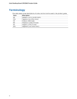
Intel Desktop Board DP55WG Product Guide Terminology The table below gives descriptions of some common terms used in the product guide. Term Description GB Gigabyte (1,073,741,824 bytes) GHz Gigahertz (one billion hertz) KB Kilobyte (1024 bytes) MB Megabyte (1,048,576 bytes) Mb Megabit - Intel DP55WG | Product Guide - Page 5
Contents 1 Desktop Board Features Supported Operating Systems 11 Desktop Board Components 12 Processor ...14 Main Memory...15 Intel® P55 Express Chipset 16 Audio Subsystem 16 LAN Subsystem 16 USB 2.0 Support 17 Serial ATA Support 17 Legacy I/O ...19 Expandability...19 BIOS ...19 Serial ATA - Intel DP55WG | Product Guide - Page 6
Headers 48 S/PDIF Header 49 Front Panel Intel HD Audio Header 49 Consumer IR (CIR) Headers 49 Front Panel Header 50 Alternate Front Panel Power LED Header 51 USB 2.0 Headers 51 IEEE 1394a Header 52 Chassis Intrusion Header 52 Connecting to the Audio System 53 Connecting Chassis Fan - Intel DP55WG | Product Guide - Page 7
12 2. LAN Connector LEDs 17 3. SATA Drive Activity LED 18 4. Location of the Standby Power Indicator 23 5. Onboard Power Button 25 6. Location of the Processor and Voltage Regulator LEDs 26 7. Location of the Back to BIOS Button 27 8. Installing the I/O Shield 31 9. Intel Desktop Board DP55WG - Intel DP55WG | Product Guide - Page 8
Intel Desktop Board DP55WG Product Guide 28. Back Panel Audio Connectors 53 29. Location of the Chassis Fan Headers 54 30. Connecting Power Supply Cables 55 31. Location of the BIOS Configuration Jumper Block 56 32. Removing the Battery 63 33. Location of the POST Code LED Display 73 34. Intel - Intel DP55WG | Product Guide - Page 9
features of Intel® Desktop Board DP55WG. Table 1 summarizes the major features of the Desktop Board. Table 1. Feature Summary Form Factor Processor Main Memory ATX (304.80 millimeters [12.00 inches] x 243.84 millimeters [9.60 inches]) Support for an Intel® processor in the LGA1156 package • Four - Intel DP55WG | Product Guide - Page 10
Intel Desktop Board DP55WG Product Guide Table 1. Feature Summary (continued) RAID Intel® Matrix Storage Technology for Serial ATA LAN Support Intel 82578DM Gigabit (10/100/1000 Mb/s) Ethernet LAN controller including an RJ-45 back panel connector with integrated status LEDs BIOS • Intel® - Intel DP55WG | Product Guide - Page 11
Desktop Board Features Supported Operating Systems The Desktop Board supports the following operating systems: • Microsoft Windows* 7 Ultimate 64-bit edition • Microsoft Windows 7 Ultimate 32-bit edition • Microsoft Windows 7 Home Basic 64-bit edition • Microsoft Windows 7 Home Basic 32-bit edition - Intel DP55WG | Product Guide - Page 12
Intel Desktop Board DP55WG Product Guide Desktop Board Components Figure 1 shows the approximate location of the major components on Intel Desktop Board DP55WG. Figure 1. Intel Desktop Board DP55WG Components 12 - Intel DP55WG | Product Guide - Page 13
fan header Processor LED Voltage regulator LED Processor socket POST code LED display DDR3 Channel A, DIMM 0 and DIMM 1 sockets DDR3 Channel B, DIMM 0 and DIMM 1 sockets Onboard power button Standby power indicator LED Main power connector (2 x 12 pin) SATA drive activity LED Front panel header - Intel DP55WG | Product Guide - Page 14
for Intel Desktop Board DP55WG http://www.intel.com/products/motherboard/DP55WG /index.htm • Supported processors http://processormatch.intel.com • Chipset information http://www.intel.com/products/desktop/chipsets/inde x.htm • BIOS and driver updates http://downloadcenter.intel.com - Intel DP55WG | Product Guide - Page 15
1600 or higher memory support on this desktop board requires compatible XMP-enabled memory or advanced knowledge of BIOS and manual memory tuning. Individual results may vary. • Support for single- and dual-channel memory interleaving • Unbuffered, non-registered single- or double-sided DIMMs with - Intel DP55WG | Product Guide - Page 16
Intel Desktop Board DP55WG Product Guide Intel® P55 Express Chipset The Intel P55 Express Chipset consists of the Intel P55 Express Platform Controller Hub (PCH). The PCH is the centralized controller for the board's I/O paths. Audio Subsystem The onboard audio subsystem consists of the following - Intel DP55WG | Product Guide - Page 17
system and drivers that fully support USB 2.0 transfer rates. Disabling Hi-Speed USB in the BIOS reverts all USB 2.0 ports to USB 1.1 operation. This may be required to accommodate operating systems that do not support USB 2.0. Serial ATA Support Intel Desktop Board DP55WG supports six onboard - Intel DP55WG | Product Guide - Page 18
Intel Desktop Board DP55WG Product Guide Figure 3. SATA Drive Activity LED The six onboard SATA channels support the following Intel Matrix Storage Technology RAID (Redundant Array of Independent Drives) levels: • RAID 0 - data striping • RAID 1 - data mirroring • RAID 0+1 (or RAID 10) - data - Intel DP55WG | Product Guide - Page 19
wake up event interface • PCI power management support Expandability Intel Desktop Board DP55WG provides the following expansion capability: • One PCI Express 2.0 x16 port (x8/x16 electrical) • One PCI Express 2.0 x8 port (x8 electrical; x16 compatible) • One PCI Express 2.0 x4 port (x4 electrical - Intel DP55WG | Product Guide - Page 20
password to boot the computer. Related Links: For instructions on resetting the password, go to "Clearing Passwords" on page 57. Hardware Management The hardware management features of Intel Desktop Board DP55WG enable the board to be compatible with the Wired for Management (WfM) specification. The - Intel DP55WG | Product Guide - Page 21
the following hardware support: • Power connectors • Fan headers • LAN wake capabilities • Instantly Available PC technology (Suspend to RAM) • +5 V standby power indicator LED • Wake from USB • Power Management Event signal (PME#) wakeup support • WAKE# signal wake-up support • Wake from Consumer - Intel DP55WG | Product Guide - Page 22
-loop fan control that can adjust the fan speed or switch the fan on or off as needed. • All fan headers have a +12 V DC connection. The Desktop Board has a 4-pin processor fan header and two 4-pin chassis fan headers. LAN Wake Capabilities CAUTION For LAN wake capabilities, the 5 V standby line - Intel DP55WG | Product Guide - Page 23
present at the memory module sockets and the PCI bus connectors. Figure 4. Location of the Standby Power Indicator For more information on standby current requirements for the Desktop Board, refer to the Technical Product Specification at http://support.intel.com/support/motherboards/desktop/. 23 - Intel DP55WG | Product Guide - Page 24
Intel Desktop Board DP55WG Product Guide Wake from USB NOTE Wake from USB requires the use of a USB peripheral that supports Wake from USB and an operating system that supports Wake from USB. USB bus activity wakes the computer from an ACPI S1 or S3 state. PME# Signal Wake-up Support When the PME# - Intel DP55WG | Product Guide - Page 25
and attaching it to a metal part of the computer chassis. The power button on the Desktop Board (see Figure 5) can be used to turn the computer on or off. The button duplicates the function of the front panel power button. To turn off the computer using the onboard power button, press it for three - Intel DP55WG | Product Guide - Page 26
Intel Desktop Board DP55WG Product Guide Processor and Voltage Regulator LEDs The Desktop Board contains two red LEDs (see Figure 6) that indicate the status of the board's voltage regulation circuitry and the processor: • The Processor LED (Figure 6, A) indicates an elevated temperature on the - Intel DP55WG | Product Guide - Page 27
. • It cannot be used to invoke BIOS recovery mode. The button glows red when it is activated. NOTE Using the Back to BIOS button does not set the board to the factory BIOS defaults. To restore settings to the factory defaults, use the key once BIOS setup mode is active. Figure 7. Location of - Intel DP55WG | Product Guide - Page 28
audible error code (beep code) information during the Power-On Self-Test (POST). Refer to Appendix A for a description of the board's beep codes. Battery A battery on the Desktop Board keeps the values in CMOS RAM and the clock current when the computer is turned off. Go to page 58 for instructions - Intel DP55WG | Product Guide - Page 29
the I/O shield • Install and remove the Desktop Board • Install and remove a processor • Install and remove memory • Install and remove a PCI Express x16 graphics card • Connect the Serial ATA cables • Connect to the internal headers • Connect to the audio system • Connect chassis fan and power - Intel DP55WG | Product Guide - Page 30
Intel Desktop Board DP55WG Product Guide Installation Precautions When you install and test the Intel Desktop Board, observe all warnings and cautions in the installation instructions. To avoid injury, be careful of: • Sharp pins on connectors • Sharp pins on printed circuit assemblies • Rough edges - Intel DP55WG | Product Guide - Page 31
components from dust and foreign objects, and promotes correct airflow within the chassis. Install the I/O shield before installing the Desktop Board in the chassis. Place the shield inside the chassis as shown in Figure 8. Press the shield into place so that it fits tightly and securely. If the - Intel DP55WG | Product Guide - Page 32
Intel Desktop Board DP55WG Product Guide Installing and Removing the Desktop Board CAUTION Only qualified manual for instructions on installing and removing the Desktop Board. Figure 9 shows the location of the mounting screw holes for Intel Desktop Board DP55WG. Figure 9. Intel Desktop Board DP55WG - Intel DP55WG | Product Guide - Page 33
and Removing a Processor Instructions on how to install the processor on the Desktop Board are given below. Installing a Processor CAUTION Before installing or removing a processor, make sure the AC power has been removed by unplugging the power cord from the computer; the standby power LED should - Intel DP55WG | Product Guide - Page 34
Intel Desktop Board DP55WG Product Guide 3. Rotate the socket lever to lift the load plate away from the socket (Figure 11, A). Make sure that the load plate is in the fully open position (Figure 11, B) while being careful not to damage adjacent components. Figure 11. Lift the Load Plate 34 - Intel DP55WG | Product Guide - Page 35
Desktop Board Components 4. Remove the protective socket cover from the socket by placing your thumb against the front edge of the cover and resting your index finger on the rear grip (Figure 12, A). Lift the front if you remove the processor from the socket. Figure 12. Remove the Socket Cover 35 - Intel DP55WG | Product Guide - Page 36
Intel Desktop Board DP55WG Product Guide 5. Remove the processor from its protective cover. Hold the processor only at the edges, being careful not to touch the bottom of the processor (see Figure 13). NOTE Do not discard the processor cover. Always replace the processor cover if the you remove the - Intel DP55WG | Product Guide - Page 37
Installing and Replacing Desktop Board Components 7. Lower the load plate over the processor while leaving the socket lever in the open position (Figure 15). Figure 15. Lower the Load Plate 8. Lower the socket lever (Figure 16, B) while making sure that the front edge of the load plate slides under - Intel DP55WG | Product Guide - Page 38
Intel Desktop Board DP55WG Product Guide Installing the Processor Fan Heat Sink Intel Desktop Board DP55WG has mounting holes for a processor fan heat sink. For instructions on how to attach the processor fan heat sink to the Desktop Board, refer to the boxed processor manual or boxed thermal - Intel DP55WG | Product Guide - Page 39
Replacing Desktop Board Components Installing and Removing System Memory Desktop board DP55WG has four 240-pin DDR3 DIMM sockets arranged as DIMM 0 and DIMM 1 in both Channel A and Channel B. NOTE The Intel P55 Express Chipset requires memory to be installed in the Channel A, DIMM 0 slot. Guidelines - Intel DP55WG | Product Guide - Page 40
Intel Desktop Board DP55WG Product Guide Figure 19. Example Dual Channel Memory Configuration with Four DIMMs Three DIMMs If you want to use three DIMMs in a dual-channel configuration, install a matched pair of DIMMs equal in speed - Intel DP55WG | Product Guide - Page 41
Installing and Replacing Desktop Board Components Installing DIMMs To make sure you have the correct DIMM, place it on the illustration of the DDR3 DIMM in Figure 21. All the notches should match with the DDR3 DIMM. Figure 21. Use DDR3 DIMMs 41 - Intel DP55WG | Product Guide - Page 42
Intel Desktop Board DP55WG Product Guide NOTE For best memory performance, install memory in the blue DIMM sockets first. To install a DIMM, follow these steps: 1. Observe the precautions in "Before You Begin" on page 29. 2. Turn off all - Intel DP55WG | Product Guide - Page 43
Installing and Replacing Desktop Board Components 10. Reinstall the PCI Express graphics card (see Installing a PCI Express x16 Graphics Card on across the connector pins. Depending on the over-current protection of the power supply, certain Desktop Board components and/or traces may be damaged. 43 - Intel DP55WG | Product Guide - Page 44
Intel Desktop Board DP55WG Product Guide Follow these instructions to install a PCI Express x16 graphics card . 2. Remove the screw (Figure 24, A) that secures the card's metal bracket to the chassis back panel. 3. Push the card ejector lever down using the tip of a pencil or similar tool (Figure 24, - Intel DP55WG | Product Guide - Page 45
Graphics Cards The Desktop Board supports technology that allows you to install linked PCI Express graphics cards such as NVIDIA* SLI* (Scalable Link Interface) cards. Make sure you use two identical SLI-ready graphics cards that are NVIDIA certified and the latest graphics driver. You can use - Intel DP55WG | Product Guide - Page 46
Intel Desktop Board DP55WG Product Guide 6. Connect the monitor cable to the graphics card according to the manufacturer's instructions. Figure 25. Installing Linked PCI Express Graphics Cards For more complete installation and configuration information refer to the documentation supplied by the - Intel DP55WG | Product Guide - Page 47
Components Connecting the Serial ATA (SATA) Cables SATA cables support the Serial ATA protocol. Each cable can be used to connect one internal SATA drive to the Desktop Board. For correct cable function: 1. Observe the precautions in "Before You Begin" on page 29. 2. Attach one end of the SATA cable - Intel DP55WG | Product Guide - Page 48
Intel Desktop Board DP55WG Product Guide Connecting to the Internal Headers Before connecting cables to any of the internal headers, observe the precautions in "Before You Begin" on page 29. Figure 27 shows the location of the internal headers and connectors on Intel Desktop Board DP55WG. Figure 27. - Intel DP55WG | Product Guide - Page 49
Intel HD Audio header. Table 5. Front Panel Intel HD Audio Header Signal Names Pin Signal Name 1 PORT 1L 3 PORT 1R 5 PORT 2R 7 SENSE_SEND 9 PORT 2L Pin Signal Name 2 GND 4 PRESENCE# 6 SENSE1_RETURN 8 KEY (no pin) 10 SENSE2_RETURN Consumer IR (CIR) Headers The Desktop Board - Intel DP55WG | Product Guide - Page 50
Intel Desktop Board DP55WG Product Guide Table 6 shows the pin assignments and signal names for the front panel CIR receiver (input) header and Table 7 shows the pin assignments and signal names for the back panel CIR emitter (output) header. Table 6. Front Panel CIR Receiver (Input) Header Signal - Intel DP55WG | Product Guide - Page 51
Installing and Replacing Desktop Board Components Alternate Front Panel Power LED Header Figure 27, F shows the location of the alternate front panel power LED header. Pins 1 and 3 of this header duplicate the signals on pins 2 and 4 of the front panel header. If your chassis has a three-pin power - Intel DP55WG | Product Guide - Page 52
Intel Desktop Board DP55WG Product Guide IEEE 1394a Header Figure 27, H shows the location of the IEEE 1394a header. Table 11 shows the pin assignments and signal names for the IEEE 1394a header. Table 11. IEEE 1394a Header Signal Names Pin Signal Name 1 TPA1+ 3 Ground 5 TPA2+ 7 +12 V 9 - Intel DP55WG | Product Guide - Page 53
Installing and Replacing Desktop Board Components Connecting to the Audio System After installing the Realtek audio driver from the Intel® Express Installer DVD-ROM, the multi-channel audio feature can be enabled. Figure 28 shows the back panel audio connectors. The connector assignments are shown - Intel DP55WG | Product Guide - Page 54
Intel Desktop Board DP55WG Product Guide Connecting Chassis Fan and Power Supply Cables Connecting Chassis Fan Cables Connect chassis fan cables to the chassis fan headers on the Desktop Board. Figure 29 shows the location of the chassis fan headers. Figure 29. Location of the Chassis Fan Headers 54 - Intel DP55WG | Product Guide - Page 55
and/or not connecting the 12 V power connector (Figure 30, A) to the Desktop Board may result in damage to the board or the system may not function properly. The 2 x 12 pin main power connector (Figure 30, C) is backwards compatible with ATX12V power supplies with 2 x 10 connectors. Use of the SATA - Intel DP55WG | Product Guide - Page 56
Intel Desktop Board DP55WG Product Guide 1. Observe the precautions in "Before You Begin" on page 29. 2. Connect the 12 V processor core voltage power supply cable to the 2 x 4 pin connector (Figure 30, A) . 3. Connect the main power supply cable to the 2 x 12 pin connector (Figure 30, C). 4. If - Intel DP55WG | Product Guide - Page 57
and Replacing Desktop Board Components Table 13. Jumper Settings for the BIOS Setup Program Modes Jumper Setting Mode Normal (default) (1-2) Description The BIOS uses the current configuration and passwords for booting. Configure (2-3) After the Power-On Self-Test (POST) runs, the BIOS displays - Intel DP55WG | Product Guide - Page 58
Intel Desktop Board DP55WG Product Guide 8. Use the arrow keys to select Clear Passwords. Press and Setup displays a pop-up screen requesting that you confirm clearing the password. Select Yes and press . Setup displays the maintenance menu again. 9. Press to save the current - Intel DP55WG | Product Guide - Page 59
Installing and Replacing Desktop Board Components OBS! Det kan oppstå eksplosjonsfare hvis batteriet skiftes ut med feil type. Brukte batterier bør kastes i henhold til gjeldende miljølovgivning. VIKTIGT! Risk för explosion om - Intel DP55WG | Product Guide - Page 60
Intel Desktop Board DP55WG Product Guide AŚCIAROŽZNA UPOZORNÌNÍ V případě výměny baterie za nesprávný druh může dojít k výbuchu. Je-li to možné, baterie by měly být recyklovány. Baterie je třeba zlikvidovat v - Intel DP55WG | Product Guide - Page 61
Installing and Replacing Desktop Board Components UPOZORNENIE Ak batériu vymeníte za nesprávny typ, hrozí nebezpečenstvo jej výbuchu. Batérie by sa mali podľa možnosti vždy - Intel DP55WG | Product Guide - Page 62
Intel Desktop Board DP55WG Product Guide 62 - Intel DP55WG | Product Guide - Page 63
Installing and Replacing Desktop Board Components To replace the battery, follow these steps: 1. Observe source (wall outlet or power adapter). 3. Remove the computer cover. 4. Locate the battery on the board (see Figure 32). 5. With a medium flat-bladed screwdriver, gently pry the battery free from - Intel DP55WG | Product Guide - Page 64
Intel Desktop Board DP55WG Product Guide 64 - Intel DP55WG | Product Guide - Page 65
of the Intel® Flash Memory Update Utility and the ease of use of Windows-based installation wizards. To update the BIOS with the Intel Express BIOS Update utility: 1. Go to the Intel World Wide Web site: http://support.intel.com/support/motherboards/desktop/ 2. Navigate to the DP55WG page, click - Intel DP55WG | Product Guide - Page 66
Memory Update Utility You can obtain either of these files through your computer supplier or by navigating to the Intel Desktop Board DP55WG page on the Intel World Wide Web site at: http://support.intel.com/support/motherboards/desktop Navigate to the DP55WG page, click "[view] Latest BIOS updates - Intel DP55WG | Product Guide - Page 67
USB flash drive or other bootable USB media. The Iflash Memory update utility allows you to: • Update the BIOS and Intel Management Engine in flash memory • Update the language section of the BIOS NOTE Review the instructions distributed with the update utility before attempting a BIOS update - Intel DP55WG | Product Guide - Page 68
Intel Desktop Board DP55WG Product Guide CAUTION Do not interrupt the process or the system may not function properly. 1. Uncompress the BIOS update file and copy the .BIO file, IFLASH.EXE, and .ITK file (optional) to a bootable USB flash drive or other bootable USB media. 2. Configure the BIOS or - Intel DP55WG | Product Guide - Page 69
more SATA hard drives to the black SATA connectors. 2. Enter system BIOS Setup by pressing after the Power-On-Self-Test (POST) memory tests begin. 3. Go to Advanced Drive Configuration Configure SATA as; ensure that RAID is selected. 4. Then save your settings by pressing . Creating Your - Intel DP55WG | Product Guide - Page 70
on supported USB floppy disk drives. Install the Intel® SATA RAID Controller driver. 3. Finish the Windows installation and install all necessary drivers. 4. Install the Intel Matrix Storage Console software via the Intel Express Installer CD included with your Desktop Board or after downloading it - Intel DP55WG | Product Guide - Page 71
codes) BIOS Error Codes Whenever a recoverable error occurs during POST, the BIOS causes the board's speaker to beep and the front panel power LED to blink an error message indicating the problem (see Table 14). Table 14. BIOS Beep Codes Type Pattern Processor One 0.5 second beep when the CPU - Intel DP55WG | Product Guide - Page 72
Intel Desktop Board DP55WG Product Guide BIOS Error Messages When a recoverable error occurs during the POST, the BIOS displays an error message describing the problem. Table 16 gives an explanation of the BIOS error messages. Table 16. BIOS Error Messages Error Message - Intel DP55WG | Product Guide - Page 73
Error Messages and Indicators Port 80h POST Codes During the POST, the BIOS generates diagnostic progress codes (POST codes) to I/O port 80h. If the POST fails, execution stops and the last POST code generated is left at port 80h and displayed on the Desktop Board's seven-segment LED display shown - Intel DP55WG | Product Guide - Page 74
Intel Desktop Board DP55WG Product Guide Table 17 lists the Port 80h POST codes in hexadecimal notation. Table 17. Port 80h POST Codes POST Code Description 00 01-05 10, 20, 30, 40, 50 ACPI S States Entering S0 state, standard Entering S1-S5 state Resuming from S1-S5 state 08 - Intel DP55WG | Product Guide - Page 75
driver entry Entered DXE phase Waiting for user input Checking password Entering BIOS setup Calling legacy option ROMs Keyboard/Mouse (PS/2 or USB) Keyboard initialization Mouse initialization Fixed Media Detecting and initializing fixed media Runtime Phase/EFI Operating System Boot EFI boot service - Intel DP55WG | Product Guide - Page 76
Intel Desktop Board DP55WG Product Guide 76 - Intel DP55WG | Product Guide - Page 77
statements • Electromagnetic Compatibility (EMC) regulations • Product certifications Safety Standards Intel Desktop Board DP55WG complies with the Place Battery Marking There is insufficient space on this Desktop Board to provide instructions for replacing and disposing of the Lithium ion coin - Intel DP55WG | Product Guide - Page 78
Intel Desktop Board DP55WG Product Guide European Union Declaration of Conformity Statement We, Intel Corporation, declare under our sole responsibility that the product Intel® Desktop Board DP55WG is in conformity with all applicable essential requirements necessary for CE marking, following the - Intel DP55WG | Product Guide - Page 79
consumers of Intel's branded products to return used products to selected locations for proper recycling. Please consult http://www.intel.com/intel/other/ehs/product_ecology for the details of this program, including the scope of covered products, available locations, shipping instructions, terms - Intel DP55WG | Product Guide - Page 80
Intel Desktop Board DP55WG Product Guide Deutsch Als Teil von Intels Engagement für den Umweltschutz hat das Unternehmen das Intel Produkt-Recyclingprogramm implementiert, das Einzelhandelskunden von Intel instructions d'expédition, les conditions générales, etc. http://www.intel.com/intel/other - Intel DP55WG | Product Guide - Page 81
produtos cobertos, os locais disponíveis, as instruções de envio, os termos e condições, etc. Russian Intel Intel (Product Recycling Program Intel http://www.intel.com/intel/other/ehs/product_ecology Türkçe Intel, çevre sorumluluğuna bağımlılığının bir parçası olarak, perakende tüketicilerin - Intel DP55WG | Product Guide - Page 82
Intel Desktop Board DP55WG Product Guide Lead-free 2LI/Pb-free 2LI Board The electronics industry is acceptable because of the RoHS "flip chip" or "die bump" interconnect exemption. Intel Desktop Board DP55WG is a lead-free second level interconnect product. Table 19 shows the lead-free - Intel DP55WG | Product Guide - Page 83
components in which the Pb concentration level in the Desktop Board substrate and the solder connections from the board to or the components (second-level interconnect) is 0.01% or 100 ppm) by weight of homogeneous material. Intel Desktop Board DP55WG complies with these restrictions. 83 - Intel DP55WG | Product Guide - Page 84
Intel Desktop Board DP55WG Product Guide China RoHS "China RoHS" is the term used by industry generally to describe legislation implemented by the Ministry of Information Industry (MII) in the People's Republic of China for the control of pollution by electronic information products (EIP). The - Intel DP55WG | Product Guide - Page 85
Regulatory Compliance The China MII stipulates that a material Self Declaration Table (SDT) must be included in a product's user documentation. The SDT for Intel Desktop Board DP55WG is shown in Figure 34. Figure 34. Intel Desktop Board DP55WG China RoHS Material Self Declaration Table 85 - Intel DP55WG | Product Guide - Page 86
Intel Desktop Board DP55WG Product Guide EMC Regulations Intel Desktop Board DP55WG complies with the EMC regulations stated in Table 21 when correctly installed in a compatible host system. Table 21. EMC Regulations Regulation (Class B) FCC 47 CFR Part 15, Subpart B ICES-003 Issue 4 EN55022: - Intel DP55WG | Product Guide - Page 87
environments and other non-residential environments. Ensure Electromagnetic Compatibility (EMC) Compliance Before computer integration, make sure that instructions for the host chassis, power supply, and other modules: • Product certifications or lack of certifications • External I/O cable shielding - Intel DP55WG | Product Guide - Page 88
Intel Desktop Board DP55WG Product Guide Product Certifications Board-Level Certification Markings Intel Desktop Board DP55WG has the product certification markings shown in Table 22. Table 22. Product Certification Markings Description UL joint US/Canada Recognized Component mark. Includes - Intel DP55WG | Product Guide - Page 89
interference (EMI) requirements. In Canada A nationally recognized certification mark such as CSA or cUL signifies compliance with safety requirements. The Industry Canada statement at the front of this product guide demonstrates compliance with Canadian EMC regulations. 89 - Intel DP55WG | Product Guide - Page 90
Intel Desktop Board DP55WG Product Guide 90
-
 1
1 -
 2
2 -
 3
3 -
 4
4 -
 5
5 -
 6
6 -
 7
7 -
8
-
9
-
10
-
11
-
12
-
13
-
14
-
15
-
16
-
17
-
18
-
19
-
20
-
21
-
22
-
23
-
24
-
25
-
26
-
27
-
28
-
29
-
30
-
31
-
32
-
33
-
34
-
35
-
36
-
37
-
38
-
39
-
40
-
41
-
42
-
43
-
44
-
45
-
46
-
47
-
48
-
49
-
50
-
51
-
52
-
53
-
54
-
55
-
56
-
57
-
58
-
59
-
60
-
61
-
62
-
63
-
64
-
65
-
66
-
67
-
68
-
69
-
70
-
71
-
72
-
73
-
74
-
75
-
76
-
77
-
78
-
79
-
80
-
81
-
82
-
83
-
84
-
85
-
86
-
87
-
88
-
89
-
90
 |
 |

Intel
®
Desktop Board DP55WG
Product Guide
Order Number:
E62931-003