Intel DP67DE DP67DE Technical Product Specification
Intel DP67DE Manual
 |
View all Intel DP67DE manuals
Add to My Manuals
Save this manual to your list of manuals |
Intel DP67DE manual content summary:
- Intel DP67DE | DP67DE Technical Product Specification - Page 1
Specification June 2012 Order Number: G14698-004 The Intel Desktop Board DP67DE may contain design defects or errors known as errata that may cause the product to deviate from published specifications. Current characterized errata are documented in the Intel Desktop Board DP67DE Specification Update - Intel DP67DE | DP67DE Technical Product Specification - Page 2
Board Identification Information section Update to the Board Identification Information section Update to the Board Identification Information section Date January 2011 January 2012 April 2012 June 2012 This product specification applies to only the standard Intel® Desktop Board DP67DE with BIOS - Intel DP67DE | DP67DE Technical Product Specification - Page 3
Hub (PCH) 82P67 Platform Controller Hub (PCH) Stepping B2 B3 S-Spec Numbers SLH84 SLJ4C Errata Current characterized errata, if any, are documented in a separate Specification Update. See http://developer.intel.com/products/desktop/motherboard/index.htm for the latest documentation. iii - Intel DP67DE | DP67DE Technical Product Specification - Page 4
Intel Desktop Board DP67DE Technical Product Specification iv - Intel DP67DE | DP67DE Technical Product Specification - Page 5
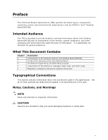
Description A description of the hardware used on Intel Desktop Board DP67DE A map of the resources of the Intel Desktop Board The features supported by the BIOS Setup program A description of the BIOS error messages, beep codes, and POST codes Regulatory compliance and battery disposal information - Intel DP67DE | DP67DE Technical Product Specification - Page 6
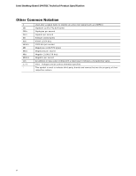
Intel Desktop Board DP67DE Technical Product Specification Other Common Notation # GB GB/s Gb/s KB Kbit kbits/s MB MB/s Mbit Mbits/s xxh x.x V * Used after a signal name to identify an active-low signal (such - Intel DP67DE | DP67DE Technical Product Specification - Page 7
1.1 Overview 11 1.1.1 Feature Summary 11 1.1.2 Board Layout 13 1.1.3 Block Diagram 15 1.2 Legacy Considerations 16 1.3 Online Support 16 1.4 Processor 17 1.4.1 PCI Express x16 Graphics 17 1.5 System Memory 18 1.5.1 Memory Configurations 19 1.6 Intel® P67 Express Chipset 21 1.6.1 USB 21 - Intel DP67DE | DP67DE Technical Product Specification - Page 8
and Configuration 65 3.9.2 BIOS Boot Optimizations 65 3.10 BIOS Security Features 66 3.11 BIOS Performance Features 67 4 Error Messages and Beep Codes 4.1 Speaker 69 4.2 BIOS Beep Codes 69 4.3 Front-panel Power LED Blink Codes 70 4.4 BIOS Error Messages 70 4.5 Port 80h POST Codes 71 viii - Intel DP67DE | DP67DE Technical Product Specification - Page 9
Support 24 5. LAN Connector LED States 27 6. Effects of Pressing the Power Switch 30 7. Power States and Targeted System Power 31 8. Wake-up Devices and Events 32 9. System Memory Map 39 10. Component-side Connectors and Headers Shown in Figure 10 42 11. IEEE 1394a Header 43 12. Front Panel - Intel DP67DE | DP67DE Technical Product Specification - Page 10
Intel Desktop Board DP67DE Technical Product Specification 17. Chassis Intrusion Header 44 18. Processor, Front, and Rear Chassis (4-Pin) Fan Headers 44 19. Back Panel CIR Emitter (Output) Header 44 20. Front Panel CIR Receiver (Input) Header 45 21. Processor Core Power Connector 46 22. Main - Intel DP67DE | DP67DE Technical Product Specification - Page 11
.84 millimeters by 243.84 millimeters]) • Intel® Core™ i7, Intel® Core™ i5, and Intel® Core™ i3 processors with up to 95W TDP in an LGA1155 socket ― One PCI Express* 2.0 x16 graphics interface ― Integrated memory controller with dual channel DDR3 memory support • Four 240-pin DDR3 SDRAM Dual Inline - Intel DP67DE | DP67DE Technical Product Specification - Page 12
for PCI* Local Bus Specification Revision 2.2 • Support for PCI Express* Revision 2.0 • Suspend to RAM support • Wake on PCI, PCI Express, LAN, front panel, Consumer Infrared (CIR), and USB ports Gigabit (10/100/1000 Mbits/s) LAN subsystem using the Intel® 82579V Gigabit Ethernet Controller Legacy - Intel DP67DE | DP67DE Technical Product Specification - Page 13
Product Description 1.1.2 Board Layout Figure 1 shows the location of the major components on Intel Desktop Board DP67DE. Figure 1. Major Board Components 13 - Intel DP67DE | DP67DE Technical Product Specification - Page 14
Intel Desktop Board DP67DE Technical Product Specification Table 2 lists the front panel header PCI Express x1 bus add-in card connector PCI Express x16 bus add-in card connector Back panel connectors Processor core power connector (2 x 2) Rear chassis fan header LGA1155 processor socket Processor - Intel DP67DE | DP67DE Technical Product Specification - Page 15
Product Description 1.1.3 Block Diagram Figure 2 is a block diagram of the major functional areas of the board. Figure 2. Block Diagram 15 - Intel DP67DE | DP67DE Technical Product Specification - Page 16
Board Support Available configurations for Intel Desktop Board DP67DE Visit this World Wide Web site: http://www.intel.com/products/motherboard/index.htm http://www.intel.com/p/en_US/support?iid=hdr+support http://ark.intel.com Supported processors Chipset information BIOS and driver updates - Intel DP67DE | DP67DE Technical Product Specification - Page 17
board has specific requirements for providing power to the processor. Refer to Section 2.5.1 on page 53 for information on power supply requirements for this board. 1.4.1 PCI Express x16 Graphics The Intel Core i7, Intel Core i5, and Intel Core i3 processors in an LGA1155 socket support discrete - Intel DP67DE | DP67DE Technical Product Specification - Page 18
Intel Desktop Board DP67DE Technical Product Specification 1.5 System Memory The board has four DIMM sockets and supports the following memory features: • 1.5 V DDR3 SDRAM DIMMs with gold plated contacts, with the option to raise the voltage to support higher performance DDR3 SDRAM DIMMs. • Support - Intel DP67DE | DP67DE Technical Product Specification - Page 19
Product Description 1.5.1 Memory Configurations The Intel Core i7, Intel Core i5, and Intel Core i3 processors in the LGA1155 socket support the following types of memory organization: • Dual channel (Interleaved) mode. This mode offers the highest throughput for real world applications. Dual - Intel DP67DE | DP67DE Technical Product Specification - Page 20
Intel Desktop Board DP67DE Technical Product Specification Figure 3 illustrates the memory channel and DIMM configuration. Figure 3. Memory Channel and DIMM Configuration NOTE The Intel Core i7, Intel Core i5, and Intel Core i3 processors require memory to be populated in the DIMM 1 (Channel A, DIMM - Intel DP67DE | DP67DE Technical Product Specification - Page 21
to the processor and the USB, SATA, LPC, LAN, PCI, and PCI Express interfaces. The Intel P67 Express Chipset is a centralized controller for the board's I/O paths. For information about The Intel P67 chipset Resources used by the chipset Refer to http://www.intel.com/products/desktop/chipsets - Intel DP67DE | DP67DE Technical Product Specification - Page 22
Intel Desktop Board DP67DE Technical Product Specification 1.7 SATA Interfaces The board provides six SATA connectors through the PCH, which support one device per preferred mode for configurations using the Windows* XP, Windows Vista*, and Windows 7* operating systems. NOTE Many SATA drives use - Intel DP67DE | DP67DE Technical Product Specification - Page 23
) levels via the Intel P67 Express Chipset: • RAID 0 - data striping • RAID 1 - data mirroring • RAID 0+1 (or RAID 10) - data striping and mirroring • RAID 5 - distributed parity NOTE In order to use supported RAID features, you must first enable RAID in the BIOS. Also, during Microsoft Windows XP - Intel DP67DE | DP67DE Technical Product Specification - Page 24
Intel Desktop Board DP67DE Technical Product Specification 1.9.1 Consumer Infrared (CIR) The Consumer Infrared (CIR) feature is designed to comply with Microsoft Consumer Infrared usage models. Microsoft Windows Vista and Microsoft Windows 7 are the supported operating systems. The CIR feature is - Intel DP67DE | DP67DE Technical Product Specification - Page 25
information about Obtaining audio software and drivers Refer to Section 1.3, page 16 1.10.2 Audio Subsystem Components The audio subsystem includes the following components: • Intel H67 Express Chipset • Realtek ALC892 audio codec • Front panel audio header that supports Intel HD audio and AC '97 - Intel DP67DE | DP67DE Technical Product Specification - Page 26
Desktop Board DP67DE Technical Product Specification NOTE The back panel audio line out connector is designed to power headphones or amplified speakers only. Poor audio quality occurs if passive (non-amplified) speakers are connected to this output. For information about The locations of the front - Intel DP67DE | DP67DE Technical Product Specification - Page 27
1.11.2 LAN Subsystem Software LAN software and drivers are available from Intel's World Wide Web site. For information about Obtaining LAN software and drivers Refer to http://downloadcenter.intel.com 1.11.3 RJ-45 LAN Connector with Integrated LEDs Two LEDs are built into the RJ-45 LAN connector - Intel DP67DE | DP67DE Technical Product Specification - Page 28
Intel Desktop Board DP67DE Technical Product Specification 1.12 Hardware Management Subsystem The hardware management features enable the board to be compatible with the Wired for Management (WfM) specification. The board has several hardware management features, including the following: • Thermal - Intel DP67DE | DP67DE Technical Product Specification - Page 29
of the thermal sensors and fan headers. Item A B C D E F Description Rear chassis fan header Thermal diode, located on the processor die Remote thermal diode Processor fan header Front chassis fan header Thermal diode, located on the Intel P67 PCH Figure 6. Thermal Sensors and Fan Headers 29 - Intel DP67DE | DP67DE Technical Product Specification - Page 30
Intel Desktop Board DP67DE Technical Product Specification 1.13 Power Management Power management is implemented at several levels, including: • Software support through Advanced Configuration and Power Interface (ACPI) • Hardware support: Power connector Fan headers LAN wake capabilities - Intel DP67DE | DP67DE Technical Product Specification - Page 31
lists the power states supported by the board along with the associated system power targets. See the ACPI specification for a complete description of the various system and power states. Table 7. Power States and Targeted System Power Global States Sleeping States Processor States Device States - Intel DP67DE | DP67DE Technical Product Specification - Page 32
Intel Desktop Board DP67DE Technical Product Specification 1.13.1.2 Wake-up Devices and Events Table 8 lists the devices or specific events that can wake the computer from specific states. Table 8. Wake-up Devices and Events These devices/events can wake up the computer... Power switch RTC alarm - Intel DP67DE | DP67DE Technical Product Specification - Page 33
program's Boot menu. For information about The location of the main power connector The signal names of the main power connector Refer to Figure 10, page 41 Table 22, page 46 1.13.2.2 Fan Headers The function/operation of the fan headers is as follows: • The fans are on when the board is in - Intel DP67DE | DP67DE Technical Product Specification - Page 34
Intel Desktop Board DP67DE Technical Product Specification 1.13.2.3 LAN Wake Capabilities CAUTION For LAN wake capabilities, the +5 V standby line for the power supply must be capable of providing adequate +5 V standby current. Failure to provide adequate standby current when implementing LAN wake - Intel DP67DE | DP67DE Technical Product Specification - Page 35
PCI Conventional bus is asserted, the computer wakes from an ACPI S3, S4, or S5 state (with Wake on PME enabled in the BIOS). 1.13.2.7 WAKE# Signal Wake-up Support When the WAKE# signal on the PCI Express bus is asserted, the computer wakes from an ACPI S3, S4, or S5 state - Intel DP67DE | DP67DE Technical Product Specification - Page 36
Intel Desktop Board DP67DE Technical Product Specification 1.13.2.10 +5 V Standby Power Indicator LED The +5 V standby power indicator LED shows that power is still present even when the computer appears to be off. Figure 7 shows - Intel DP67DE | DP67DE Technical Product Specification - Page 37
is not possible to use all of the installed memory due to system address space being allocated for other system critical functions. These functions include the following: • BIOS/SPI Flash device (16 Mbit) • Local APIC (19 MB) • Direct Media Interface (40 MB) • Front side bus interrupts (17 MB) • PCI - Intel DP67DE | DP67DE Technical Product Specification - Page 38
Intel Desktop Board DP67DE Technical Product Specification Figure 8. Detailed System Memory Address Map 38 - Intel DP67DE | DP67DE Technical Product Specification - Page 39
on video adapter used. Video memory and BIOS Extended BIOS data (movable by memory manager software) Extended conventional memory Conventional memory 2.2 Connectors and Headers CAUTION Only the following connectors and headers have overcurrent protection: back panel and front panel USB, as well as - Intel DP67DE | DP67DE Technical Product Specification - Page 40
Intel Desktop Board DP67DE Technical Product Specification 2.2.1 Back Panel Connectors Figure 9 shows the location of the back panel connectors for the board. Item A B C D E F G H I J K L M Description USB 2.0 ports eSATA connector LAN port USB 2.0 ports USB 2.0 ports IEEE 1394a connector USB 3.0 - Intel DP67DE | DP67DE Technical Product Specification - Page 41
Technical Reference 2.2.2 Component-side Connectors and Headers Figure 10 shows the locations of the component-side connectors and headers. Figure 10. Component-side Connectors and Headers 41 - Intel DP67DE | DP67DE Technical Product Specification - Page 42
Board DP67DE Technical Product Specification Table 10 lists the component-side connectors and headers identified in Figure 10. Table 10. Component-side Connectors and Headers Shown in Figure 10 Item/callout from Figure 10 Description A PCI Conventional bus add-in card connector B Front panel - Intel DP67DE | DP67DE Technical Product Specification - Page 43
1 Data A (positive) 3 Ground 5 Data B (positive) 7 +12 V DC 9 Key (no pin) Pin 2 4 6 8 10 Signal Name Data A (negative) Ground Data B (negative) +12 V DC Ground Table 12. Front Panel Audio Header for Intel HD Audio Pin Signal Name Pin Signal Name 1 [Port 1] Left channel 2 Ground - Intel DP67DE | DP67DE Technical Product Specification - Page 44
Intel Desktop Board DP67DE Technical Product Specification 18. Processor, Front, and Rear Chassis (4-Pin) Fan Headers Pin Signal Name 1 Ground (Note) 2 +12 V 3 FAN_TACH 4 FAN_CONTROL Note: These fan headers use Pulse Width Modulation control for fan speed. Table 19. Back Panel - Intel DP67DE | DP67DE Technical Product Specification - Page 45
Front Panel CIR Receiver (Input) Header Pin Signal Name 1 Ground 2 LED 3 NC 4 Learn-in 5 5 V standby 6 VCC 7 Key (no pin) 8 CIR Input 2.2.2.2 Add-in Card Connectors The board add-in boards with SMBus support to access sensor data on the desktop board. The specific SMBus signals - Intel DP67DE | DP67DE Technical Product Specification - Page 46
Intel Desktop Board DP67DE Technical Product Specification 2.2.2.3 Power Supply Connectors The board has the following power supply connectors: • Main power - a 2 x 12 connector. This connector is compatible with 2 x 10 connectors previously used on Intel Desktop boards. The board supports the use - Intel DP67DE | DP67DE Technical Product Specification - Page 47
Signal Name 2 POWER_LED_MAIN 4 POWER_LED_ALT 6 POWER_SWITCH# 8 GROUND 10 Key Description [Out] Front panel LED (main color) [Out] Front panel LED (alt color) [In] Power switch Ground No pin type switch that is normally open. When the switch is closed, the board resets and runs the POST. 47 - Intel DP67DE | DP67DE Technical Product Specification - Page 48
Intel Desktop Board DP67DE Technical Product Specification 2.2.2.4.3 Power/Sleep LED Header Pins 2 and 4 colors only. Actual LED colors are chassis-specific. 2.2.2.4.4 Power Switch Header Pins 6 and 8 can be connected to a front panel momentary-contact power switch. The switch must pull - Intel DP67DE | DP67DE Technical Product Specification - Page 49
Use only a front panel USB connector that conforms to the USB 2.0 specification for high-speed USB devices. Figure 12. Connection Diagram for Front Panel USB 2.0 Headers 2.2.2.7 Low Pin Count (LPC) Debug header During the POST, the BIOS generates diagnostic progress codes (POST codes) to I/O port - Intel DP67DE | DP67DE Technical Product Specification - Page 50
Intel Desktop Board DP67DE Technical Product Specification 2.3 Jumper Block CAUTION Do not move the jumper with the power on. Always turn off the power and unplug the power cord from the computer before changing a jumper setting. Otherwise, the board could be damaged. Figure 13 shows the location of - Intel DP67DE | DP67DE Technical Product Specification - Page 51
Setup Configuration Jumper Settings Function/Mode Normal Jumper Setting 1-2 Configuration The BIOS uses current configuration information and passwords for booting. Configure 2-3 Recovery None After the POST runs, Setup runs automatically. The maintenance menu is displayed. Note that this - Intel DP67DE | DP67DE Technical Product Specification - Page 52
Intel Desktop Board DP67DE Technical Product Specification 2.4 Mechanical Considerations 2.4.1 Form Factor The board is designed to fit into an ATX-form-factor chassis. Figure 14 illustrates the mechanical form factor for the board. Dimensions are given in inches [millimeters]. The outer dimensions - Intel DP67DE | DP67DE Technical Product Specification - Page 53
of the ATX form factor specification. • The potential relation between 3.3 V DC and +5 V DC power rails • The current capability of the +5 VSB line • All timing parameters • All voltage tolerances For example, for a system consisting of a supported 95 W processor (see Section 1.4 on page 17 - Intel DP67DE | DP67DE Technical Product Specification - Page 54
Intel Desktop Board DP67DE Technical Product Specification 2.5.2 Fan Header Current Capability CAUTION The processor fan must be connected to the processor fan header, not to a chassis fan header. Connecting the processor fan to a chassis fan header may result in onboard component damage that will - Intel DP67DE | DP67DE Technical Product Specification - Page 55
see the environmental specifications in Section 2.8. CAUTION Ensure that proper airflow is maintained in the processor voltage regulator circuit. zones. Item A B C Description Processor voltage regulator area Processor Intel P67 Express Chipset Figure 15. Localized High Temperature Zones 55 - Intel DP67DE | DP67DE Technical Product Specification - Page 56
Intel Desktop Board DP67DE Technical Product Specification in the system BIOS is a Processor For processor case temperature, see processor datasheets and processor specification updates Intel P67 Express Chipset 107 oC For information about Processor datasheets and specification updates Intel - Intel DP67DE | DP67DE Technical Product Specification - Page 57
is calculated from predicted data at 55 ºC. The MTBF for the board is 255,025 hours. 2.8 Environmental Table 33 lists the environmental specifications for the board. Table 33. Environmental Specifications Parameter Temperature Non-Operating Operating Shock Unpackaged Packaged Vibration Unpackaged - Intel DP67DE | DP67DE Technical Product Specification - Page 58
Intel Desktop Board DP67DE Technical Product Specification 58 - Intel DP67DE | DP67DE Technical Product Specification - Page 59
The board uses an Intel BIOS that is stored in the Serial Peripheral Interface Flash Memory (SPI Flash) and can be updated using a disk-based program. The SPI Flash contains the BIOS Setup program, POST, the PCI auto-configuration utility, LAN EEPROM information, and Plug and Play support. The BIOS - Intel DP67DE | DP67DE Technical Product Specification - Page 60
Intel Desktop Board DP67DE Technical Product Specification Table 34 lists the BIOS Setup program menu features. Table 34. BIOS Setup Program Menu Bar Maintenance Main Configura- tion Performance Security Clears passwords and displays processor information Displays processor and memory - Intel DP67DE | DP67DE Technical Product Specification - Page 61
and processor speed • Dynamic data, such as event detection and error logging Non-Plug and Play operating systems require an additional interface for obtaining the SMBIOS information. The BIOS supports an SMBIOS table interface for such operating systems. Using this support, an SMBIOS service-level - Intel DP67DE | DP67DE Technical Product Specification - Page 62
Intel Desktop Board DP67DE Technical Product Specification To install an operating system that supports USB, verify that Legacy USB support in the BIOS Setup program is set to Enabled and follow the operating system's installation instructions. 3.6 BIOS Updates The BIOS can be updated using either - Intel DP67DE | DP67DE Technical Product Specification - Page 63
USB removable drive (a USB Flash Drive, for example) Yes USB diskette drive (with a 1.44 MB diskette) No USB hard disk drive No For information about BIOS recovery Refer to http://www.intel.com/support/motherboards/desktop/sb /cs-023360.htm 63 - Intel DP67DE | DP67DE Technical Product Specification - Page 64
Intel Desktop Board DP67DE Technical Product Specification 3.8 Boot Options In the BIOS Setup program, the user can choose to boot from a hard drive, optical drive, removable drive, or the network. The default setting is for the optical drive to be the first boot device, the hard drive second, - Intel DP67DE | DP67DE Technical Product Specification - Page 65
from the POST execution time. • In the Peripheral Configuration submenu, disable the LAN device if it will not be used. This can reduce up to four seconds of option ROM boot time. NOTE It is possible to optimize the boot process to the point where the system boots so quickly that the Intel logo - Intel DP67DE | DP67DE Technical Product Specification - Page 66
Intel Desktop Board DP67DE Technical Product Specification 3.10 BIOS Security Features The BIOS includes security features that restrict access to the BIOS Setup program and who can boot the computer. A supervisor password and a user password can be set for the BIOS Setup program and for booting - Intel DP67DE | DP67DE Technical Product Specification - Page 67
Overview of BIOS Features 3.11 BIOS Performance Features The BIOS includes the following options to provide custom performance enhancements when using Intel Core i7, Intel Core i5, and Intel Core i3 processors in an LGA1155 socket. • Processor Maximum Non-Turbo Ratio (processor multiplier can only - Intel DP67DE | DP67DE Technical Product Specification - Page 68
Intel Desktop Board DP67DE Technical Product Specification 68 - Intel DP67DE | DP67DE Technical Product Specification - Page 69
error occurs during POST, the BIOS causes the board's speaker to beep an error message describing the problem (see Table 39). Table 39. BIOS Beep Codes Type Pattern F2 Setup/F10 Boot Menu Prompt One 0.5 second beep when BIOS is ready to accept keyboard input BIOS update in progress None - Intel DP67DE | DP67DE Technical Product Specification - Page 70
Intel Desktop Board DP67DE Technical Product Specification 4.3 Front-panel Power LED Blink Codes Whenever a recoverable error occurs during POST, the BIOS causes the board's front panel power LED to blink an error message describing the problem (see Table 40). Table 40. Front-panel Power LED - Intel DP67DE | DP67DE Technical Product Specification - Page 71
(SEC) phase 0x11 0x1F 0x21 - 0x29 0x2A - 0x2F 0x31 - 0x35 PEI phase pre MRC execution MRC memory detection PEI phase post MRC execution Recovery 0x36 - 0x3F Platform DXE driver 0x41 - 0x4F CPU Initialization (PEI, DXE, SMM) 0x50 - 0x5F I/O Buses: PCI, USB, ATA etc. 0x5F is an unrecoverable - Intel DP67DE | DP67DE Technical Product Specification - Page 72
Intel Desktop Board DP67DE Technical Product Specification Table 43. Port 80h POST Codes Port 80 Code Progress Code Enumeration ACPI S States 0x00,0x01,0x02,0x03,0x04,0x05 0x10,0x20,0x30,0x40,0x50 Entering S0, S2, S3, S4, or S5 state Resuming from S2, - Intel DP67DE | DP67DE Technical Product Specification - Page 73
Messages and Beep Codes Table 43. Port 80h POST Codes (continued) Port 80 Code Progress Code Enumeration PEIMs/Recovery 0x31 0x33 0x34 Crisis Recovery has initiated Loading recovery capsule Start recovery capsule/ valid capsule is found CPU Initialization CPU PEI Phase 0x41 Begin CPU PEI - Intel DP67DE | DP67DE Technical Product Specification - Page 74
Intel Desktop Board DP67DE Technical Product Specification Table 43. Port 80h POST Codes (continued) Port 80 Code 0x60 0x61 0x62 0x63 0x64 0x65 0x66 0x67 0x68 0x69 0x6A 0x6B 0x6C 0x6D 0x6E 0x6F 0x90 0x91 0x92 0x93 0x94 0x95 0x98 0x99 0x9A 0x9B 0xB0 0xB1 Progress Code Enumeration BDS BDS driver - Intel DP67DE | DP67DE Technical Product Specification - Page 75
and Beep Codes Table 43. Port 80h POST Codes (continued) Port 80 Code Progress Code Enumeration Core 0xE4 0xE7 Entered DXE phase Waiting for user input BDS 0xE8 Checking password 0xE9 Entering BIOS setup 0xEB Calling Legacy Option ROMs Runtime Phase/EFI OS Boot 0xF8 EFI boot service - Intel DP67DE | DP67DE Technical Product Specification - Page 76
Desktop Board DP67DE Technical Product Specification Table 44. Typical Port 80h POST Sequence POST Code Description 21 Initializing a chipset component 22 Reading SPD from memory DIMMs 23 Detecting presence of memory DIMMs 25 Configuring memory 28 Testing memory 34 Loading recovery - Intel DP67DE | DP67DE Technical Product Specification - Page 77
• Electromagnetic Compatibility (EMC) standards • Product certification markings 5.1.1 Safety Standards Intel Desktop Board DP67DE complies with the safety standards stated in Table 45 when correctly installed in a compatible host system. Table 45. Safety Standards Standard Title CSA/UL 60950 - Intel DP67DE | DP67DE Technical Product Specification - Page 78
Intel Desktop Board DP67DE Technical Product Specification 5.1.2 European Union Declaration of Conformity Statement We, Intel Corporation, declare under our sole responsibility that the product Intel® Desktop Board DP67DE is in conformity with all applicable essential requirements necessary for CE - Intel DP67DE | DP67DE Technical Product Specification - Page 79
of this program, including the scope of covered products, available locations, shipping instructions, terms and conditions, etc Intel Product Recycling Program http://www.intel.com/intel/other/ehs/product_ecology Deutsch Als Teil von Intels Engagement für den Umweltschutz hat das Unternehmen das - Intel DP67DE | DP67DE Technical Product Specification - Page 80
Intel Desktop Board DP67DE Technical Product Specification Español Como parte de su compromiso de responsabilidad medioambiental, Intel ha implantado el programa de reciclaje de productos Intel, que permite que los consumidores al detalle de los productos Intel devuelvan los productos usados en los - Intel DP67DE | DP67DE Technical Product Specification - Page 81
ına gidin. 5.1.4 EMC Regulations Intel Desktop Board DP67DE complies with the EMC regulations stated in Table 46 when correctly installed in a compatible host system. Table 46. EMC Regulations Regulation Title FCC 47 CFR Part 15, Subpart B Title 47 of the Code of Federal Regulations, Part 15 - Intel DP67DE | DP67DE Technical Product Specification - Page 82
Intel Desktop Board DP67DE Technical Product Specification FCC Declaration of Conformity This device complies with Part 15 radio frequency energy and, if not installed and used in accordance with the instructions, may cause harmful interference to radio communications. However, there is no guarantee - Intel DP67DE | DP67DE Technical Product Specification - Page 83
or television receiver in a domestic environment, it may cause radio interference. Install and use the equipment according to the instruction manual. Korea Class B Statement Korea Class B Statement translation: This equipment is for home use, and has acquired electromagnetic conformity registration - Intel DP67DE | DP67DE Technical Product Specification - Page 84
Intel Desktop Board DP67DE Technical Product Specification 5.1.5 ENERGY STAR* 5.0, e-Standby, and ErP Compliance The US Department of Energy and the US Environmental Protection Agency have continually revised the ENERGY STAR requirements. Intel has worked directly with these two governmental - Intel DP67DE | DP67DE Technical Product Specification - Page 85
Regulatory Compliance Marks (Board Level) Intel Desktop Board DP67DE has the regulatory compliance marks shown in Table 47. Table 47. Regulatory Compliance Marks Description UL joint US/Canada Recognized Component mark. Includes adjacent UL file number for Intel Desktop Boards: E210882. Mark FCC - Intel DP67DE | DP67DE Technical Product Specification - Page 86
Intel Desktop Board DP67DE Technical Product Specification 5.2 Battery Disposal Information CAUTION Risk of explosion if the battery is replaced with an incorrect type. Batteries should be recycled where possible. Disposal of used - Intel DP67DE | DP67DE Technical Product Specification - Page 87
Regulatory Compliance and Battery Disposal Information PRECAUCIÓN Existe peligro de explosión si la pila no se cambia de forma adecuada. Utilice solamente pilas iguales o del mismo tipo que las recomendadas por el fabricante del equipo. Para deshacerse de las pilas usadas, siga igualmente las - Intel DP67DE | DP67DE Technical Product Specification - Page 88
Intel Desktop Board DP67DE Technical Product Specification AWAS Risiko letupan wujud jika bateri digantikan dengan jenis yang tidak betul. Bateri sepatutnya dikitar semula jika boleh. Pelupusan bateri terpakai mestilah mematuhi peraturan alam - Intel DP67DE | DP67DE Technical Product Specification - Page 89
Regulatory Compliance and Battery Disposal Information 89 - Intel DP67DE | DP67DE Technical Product Specification - Page 90
Intel Desktop Board DP67DE Technical Product Specification 90
-
 1
1 -
 2
2 -
 3
3 -
 4
4 -
 5
5 -
 6
6 -
 7
7 -
8
-
9
-
10
-
11
-
12
-
13
-
14
-
15
-
16
-
17
-
18
-
19
-
20
-
21
-
22
-
23
-
24
-
25
-
26
-
27
-
28
-
29
-
30
-
31
-
32
-
33
-
34
-
35
-
36
-
37
-
38
-
39
-
40
-
41
-
42
-
43
-
44
-
45
-
46
-
47
-
48
-
49
-
50
-
51
-
52
-
53
-
54
-
55
-
56
-
57
-
58
-
59
-
60
-
61
-
62
-
63
-
64
-
65
-
66
-
67
-
68
-
69
-
70
-
71
-
72
-
73
-
74
-
75
-
76
-
77
-
78
-
79
-
80
-
81
-
82
-
83
-
84
-
85
-
86
-
87
-
88
-
89
-
90
 |
 |

Intel® Desktop Board
DP67DE
Technical Product Specification
June 2012
Order Number:
G14698-004
The Intel Desktop Board DP67DE may contain design defects or errors known as errata that may cause the product to deviate from published specifications.
Current characterized errata are documented in the Intel Desktop Board DP67DE Specification Update.