Intel DX79SR Product Specification
Intel DX79SR Manual
 |
View all Intel DX79SR manuals
Add to My Manuals
Save this manual to your list of manuals |
Intel DX79SR manual content summary:
- Intel DX79SR | Product Specification - Page 1
April 2012 Order Number: G62925-001 The Intel® Desktop Board DX79SR may contain design defects or errors known as errata that may cause the product to deviate from published specifications. Current characterized errata are documented in the Intel Desktop Board DX79SR Specification Update. - Intel DX79SR | Product Specification - Page 2
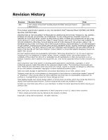
History Revision -001 Revision History First release of the Intel® Desktop Board DX79SR Technical Product Specification Date April 2012 This product specification applies to only the standard Intel® Desktop Board DX79SR with BIOS identifier SIX7910J.86A. INFORMATION IN THIS DOCUMENT IS PROVIDED - Intel DX79SR | Product Specification - Page 3
board. 2. The X79 PCH used on this AA revision consists of the following component: Device 82X79 PCH Stepping C1 S-Spec Numbers SLJN7 Errata Current characterized errata, if any, are documented in a separate Specification Update. See http://developer.intel.com/products/desktop/motherboard/index - Intel DX79SR | Product Specification - Page 4
Intel Desktop Board DX79SR Technical Product Specification iv - Intel DX79SR | Product Specification - Page 5
of the hardware used on the Intel Desktop Board DX79SR A map of the resources of the Intel Desktop Board The features supported by the BIOS Setup program A description of the BIOS error messages, beep codes, and POST codes Regulatory compliance and battery disposal information Typographical - Intel DX79SR | Product Specification - Page 6
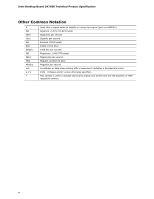
Intel Desktop Board DX79SR Technical Product Specification Other Common Notation # GB GB/s Gb/s KB Kbit kbits/s MB MB/s Mbit Mbits/s xxh x.x V * Used after a signal name to identify an active-low signal (such - Intel DX79SR | Product Specification - Page 7
Summary 11 1.1.2 Board Layout 13 1.1.3 Block Diagram 15 1.2 Legacy Considerations 16 1.3 Online Support 16 1.4 Processor 16 1.4.1 PCI Express x16 Graphics 17 1.5 System Memory 17 1.5.1 Memory Configurations 19 1.6 Intel® X79 Express Chipset 21 1.6.1 USB 21 1.6.2 SATA Interfaces 22 - Intel DX79SR | Product Specification - Page 8
65 3 Overview of BIOS Features 3.1 Introduction 67 3.2 BIOS Flash Memory Organization 68 3.3 Resource Configuration 68 3.3.1 PCI Autoconfiguration 68 3.4 System Management BIOS (SMBIOS 69 3.5 Legacy USB Support 69 3.6 BIOS Updates 70 3.6.1 Language Support 70 3.6.2 Custom Splash Screen 71 - Intel DX79SR | Product Specification - Page 9
Panel Audio Connectors 25 5. LAN Connector LED Locations 27 6. Bluetooth/WiFi Module 28 7. Thermal Sensors and Fan Headers 31 8. Location of Board Status LEDs 39 9. Location of the Onboard Power and Reset Buttons 41 10. Detailed System Memory Address Map 44 11. Back Panel Connectors 46 12 - Intel DX79SR | Product Specification - Page 10
Intel Desktop Board DX79SR Technical Product Specification 8. Wake-up Devices and Events 34 9. Board Status LEDs 40 10. System Memory Map 45 11. Component-side Connectors and Headers Shown in Figure 13 49 12. Front Panel Audio Header for Intel HD Audio 50 13. Front Panel Audio Header for AC '97 - Intel DX79SR | Product Specification - Page 11
Overview 1.1.1 Feature Summary Table 1 summarizes the major features of the board. Table 1. Feature Summary Form Factor Processor Memory Chipset Audio ATX (12.00 inches by 9.60 inches [304.80 millimeters by 243.84 millimeters]) • Intel® Core™ i7 and Intel® Xeon® processors in an LGA 2011 socket - Intel DX79SR | Product Specification - Page 12
Intel Desktop Board DX79SR Technical Product Specification Table 1. Feature Summary (continued) BIOS • Intel® BIOS resident in the SPI Flash device • Support for Advanced Configuration and Power Interface (ACPI), Plug and Play, and SMBIOS • Fast Boot • Support for advanced over clocking - Intel DX79SR | Product Specification - Page 13
Product Description 1.1.2 Board Layout Figure 1 shows the location of the major components on Intel Desktop Board DX79SR. Figure 1. Major Board Components Table 2 lists the components identified in Figure 1. 13 - Intel DX79SR | Product Specification - Page 14
/s connectors through the PCH (blue) SATA 3.0 Gb/s connectors through the PCH (black) SATA 6.0 Gb/s connectors through a Marvell 88SE9128 controller (gray) Intel X79 Express Chipset Front panel USB 2.0 headers (4) Consumer IR emitter (output) header BIOS Setup configuration jumper block Power Fault - Intel DX79SR | Product Specification - Page 15
Product Description 1.1.3 Block Diagram Figure 2 is a block diagram of the major functional areas of the board. Figure 2. Block Diagram 15 - Intel DX79SR | Product Specification - Page 16
for the Intel Desktop Board DX79SR Visit this World Wide Web site: http://www.intel.com/products/motherboard/index.htm http://www.intel.com/p/en_US/support?iid=hdr+support http://ark.intel.com Supported processors Chipset information BIOS and driver updates Tested memory Integration information - Intel DX79SR | Product Specification - Page 17
MHz • Full support for over clocking memory (see www.intel.com/support/motherboards/desktop/sb/CS-031689.htm for more information about over clocking) • DIMM slots are numbered in installation order NOTE To be fully compliant with all applicable DDR SDRAM memory specifications, the board should be - Intel DX79SR | Product Specification - Page 18
Intel Desktop Board DX79SR Technical Product Specification CAUTION 1.5 V is the recommended and default setting for DDR3 memory voltage. The other memory voltage settings in the BIOS Setup program are provided for performance tuning purposes only. Altering the memory voltage may (i) reduce system - Intel DX79SR | Product Specification - Page 19
Description 1.5.1 Memory Configurations The Intel Core i7 and Intel Xeon processors support the following types of memory organization: • slowest memory timing will be used. For information about... Memory Configuration Examples Refer to: http://www.intel.com/support/motherboards/desktop/sb - Intel DX79SR | Product Specification - Page 20
Intel Desktop Board DX79SR Technical Product Specification Figure 3 illustrates the memory channel and DIMM configuration. Figure 3. Memory Channel and DIMM Configuration NOTE For best memory performance always install memory into the blue DIMM memory sockets if installing four DIMMs or less in your - Intel DX79SR | Product Specification - Page 21
interfaces to the processor and the USB, SATA, LAN, PCI, and PCI Express interfaces. The PCH is a centralized controller for the board's I/O paths. For information about The Intel X79 Express Chipset Resources used by the chipset Refer to http://www.intel.com/products/desktop/chipsets/index.htm - Intel DX79SR | Product Specification - Page 22
Desktop Board DX79SR Technical Product Specification 1.6.2 SATA Interfaces The board provides eight SATA connectors which support one device per connector: • Two internal SATA 6.0 Gb/s connectors through the PCH (blue) • Two internal SATA 6.0 Gb/s connectors through a Marvell 88SE9128 controller - Intel DX79SR | Product Specification - Page 23
be reset and the user will be notified during POST. When the voltage drops below a certain level, the BIOS Setup program settings stored in CMOS RAM (for to control external electronic hardware. Customers are required to buy or create their own interface modules to plug into Intel Desktop Boards for - Intel DX79SR | Product Specification - Page 24
Intel Desktop Board DX79SR Technical Product Specification 1.9 Audio Subsystem The board supports the Intel High Definition Audio subsystem based on the Realtek ALC892 audio codec. The audio subsystem supports the following features: • Advanced jack sense for the back panel audio jacks that enables - Intel DX79SR | Product Specification - Page 25
Product Description Item A B C D E F Description Rear surround Center channel and LFE (subwoofer) Line in Line out/front speakers Mic in/side surround S/PDIF digital audio out (optical) Figure 4. Back Panel Audio Connectors NOTE The back panel audio line out connector is designed to power - Intel DX79SR | Product Specification - Page 26
Intel Desktop Board DX79SR Technical Product Specification 1.10 LAN Subsystem The Intel GbE Dual LAN subsystem consists of the following: • Intel 82579L and Intel 82574L Gigabit Ethernet Controllers (10/100/1000 Mbits/s) • Intel X79 Express Chipset • RJ-45 LAN connectors with integrated status LEDs - Intel DX79SR | Product Specification - Page 27
. For information about Obtaining LAN software and drivers Refer to http://downloadcenter.intel.com 1.10.3 RJ-45 LAN Connector with Integrated LEDs Two 5. LAN Connector LED Locations Table 5 describes the LED states when the board is powered up and the LAN subsystem is operating. Table 5. LAN - Intel DX79SR | Product Specification - Page 28
Intel Desktop Board DX79SR Technical Product Specification 1.11 Bluetooth*/WiFi Module The Bluetooth*/WiFi module is supplemental hardware that is included (see Figure 6). Figure 6. Bluetooth/WiFi Module 1.11.1 Bluetooth Technology The Bluetooth/WiFi Module enables the user to connect with a - Intel DX79SR | Product Specification - Page 29
and drivers Refer to http://msdn.microsoft.com/enus/library/aa362932(VS.85).aspx http://downloadcenter.intel.com 1.12 Hardware Management Subsystem The hardware management features enable the board to be compatible with the Wired for Management (WfM) specification. The board has several - Intel DX79SR | Product Specification - Page 30
Intel Desktop Board DX79SR Technical Product Specification 1.12.2 Fan Monitoring Fan monitoring can be implemented using Intel® Extreme Tuning Utility, Intel® Desktop Utility, or third-party software. For information about The functions of the fan headers Refer to Section 1.13.2.2, page 36 1.12 - Intel DX79SR | Product Specification - Page 31
thermal sensors and fan headers. Item A B C D E F G Description Rear chassis fan header Processor fan header Thermal diode, located on processor die Remote thermal probe header Front chassis fan header Intel X79 Express Chipset Auxiliary fan header Figure 7. Thermal Sensors and Fan Headers 31 - Intel DX79SR | Product Specification - Page 32
Intel Desktop Board DX79SR Technical Product Specification 1.13 Power Management Power management is implemented at several levels, including: • Software support through Advanced Configuration and Power Interface (ACPI) • Hardware support: ⎯ Power connector ⎯ Fan headers ⎯ LAN wake capabilities ⎯ - Intel DX79SR | Product Specification - Page 33
lists the power states supported by the board along with the associated system power targets. See the ACPI specification for a complete description of the various system and power states. Table 7. Power States and Targeted System Power Global States Sleeping States Processor States Device States - Intel DX79SR | Product Specification - Page 34
Intel Desktop Board DX79SR Technical Product Specification 1.13.1.2 Wake-up Devices and Events Table 8 lists the devices or specific events that can wake the computer from specific states. Table 8. Wake-up Devices and Events Devices/events can wake up the computer... Power switch RTC alarm LAN - Intel DX79SR | Product Specification - Page 35
USB from an ACPI state requires an operating system that provides full ACPI support. 1.13.2.1 Power Connector ATX12V-compliant power supplies can turn off the system power through system control set using the Last Power State feature in the BIOS Setup program's Boot menu. For information about The - Intel DX79SR | Product Specification - Page 36
Intel Desktop Board DX79SR Technical Product Specification 1.13.2.2 Fan Headers The function/operation of the fan headers is as follows: • The fans are on when the board is in the S0 state • The fans are off when the board a network. The LAN subsystem PCI bus network adapter monitors network traffic - Intel DX79SR | Product Specification - Page 37
boards that also support this specification can participate in power management and can be used to wake the computer. The use of Instantly Available PC technology requires operating system support and PCI 2.2 compliant add-in cards, PCI Express add-in cards, and drivers. 1.13.2.5 Wake from USB USB - Intel DX79SR | Product Specification - Page 38
Intel Desktop Board DX79SR Technical Product Specification 1.13.2.10 Power Supervisor The Power Supervisor actively monitors the input voltages from the power supply and protects the board and any attached peripherals from electrical overstress and possible physical damage. The Power Supervisor will - Intel DX79SR | Product Specification - Page 39
are off. When the BIOS starts an activity such as memory initialization, the corresponding LED starts flashing. Once the activity has completed, the LED will remain on. Six additional LEDs can be used to monitor board functions such as hard drive activity, processor errors, and power faults. Refer - Intel DX79SR | Product Specification - Page 40
Intel Desktop Board DX79SR Technical Product Specification Table 9. Board Status LEDs Item in Figure 8 LED Name LED Color A OS Start Green B Storage Green Initialization C USB Initialization Green D Option ROM Green Initialization E Video Green Initialization F Memory Green - Intel DX79SR | Product Specification - Page 41
or off. To turn the computer off using the onboard power button, keep the button pressed down for three seconds. The lighted onboard reset button can be used to reset the board. This button duplicates the function of the front panel reset button. Figure 9 shows the location of the onboard power and - Intel DX79SR | Product Specification - Page 42
Intel Desktop Board DX79SR Technical Product Specification 42 - Intel DX79SR | Product Specification - Page 43
2 Technical Reference 2.1 Memory Resources 2.1.1 Addressable Memory The board utilizes 64 GB of addressable system memory. Typically the address space that is allocated for Conventional PCI bus add-in cards, PCI Express configuration space, BIOS (SPI Flash device), and chipset overhead resides above - Intel DX79SR | Product Specification - Page 44
Intel Desktop Board DX79SR Technical Product Specification Figure 10. Detailed System Memory Address Map 44 - Intel DX79SR | Product Specification - Page 45
on video adapter used. Video memory and BIOS Extended BIOS data (movable by memory manager software) Extended conventional memory Conventional memory 2.2 Connectors and Headers CAUTION Only the following connectors and headers have overcurrent protection: back panel and front panel USB, as - Intel DX79SR | Product Specification - Page 46
Intel Desktop Board DX79SR Technical Product Specification 2.2.1 Back Panel Connectors Figure 11 shows the location of the back panel connectors for the board. Item A B C D E F G H I J K L M N O Description Back to BIOS button USB 3.0 ports USB 3.0 ports LAN connector USB 2.0 ports IEEE 1394a - Intel DX79SR | Product Specification - Page 47
Technical Reference 2.2.1.1 I/O Shield The I/O shield provided with the board allows access to all back panel connectors and is compatible with standard mini-ITX and ATX chassis. Figure 12 shows an I/O shield reference diagram. Figure 12. I/O Shield Reference Diagram 47 - Intel DX79SR | Product Specification - Page 48
Intel Desktop Board DX79SR Technical Product Specification 2.2.2 Component-side Connectors and Headers Figure 13 shows the locations of the component-side connectors and headers. Figure 13. Component-side Connectors and Headers Table - Intel DX79SR | Product Specification - Page 49
through the PCH (blue) P SATA 3.0 Gb/s connectors through the PCH (black) Q SATA 6.0 Gb/s connectors through a Marvell 88SE9128 controller (gray) R Front panel USB 2.0 header S Front panel USB 2.0 header T Front panel USB 2.0 header U Front panel USB 2.0 header V Consumer IR emitter - Intel DX79SR | Product Specification - Page 50
Intel Desktop Board DX79SR Technical Product Specification 2.2.2.1 Signal Tables for the Connectors and Headers Table 12. Front Panel Audio Header for Intel HD Audio Pin Signal Name Description 1 PORT_1L Analog Port 1 - left channel (microphone) 2 GND Ground 3 PORT_1R Analog Port 1 - - Intel DX79SR | Product Specification - Page 51
B (positive) 7 +12 V DC 9 Key (no pin) Table 15. SATA Connectors Pin Signal Name 1 Ground 2 TXP 3 TXN 4 Ground 5 RXN 6 VDC Table 17. USB 2.0 Headers Pin Signal Name 1 +5 V DC 2 D− 3 D+ 4 Ground 5 Key (no pin) Technical Reference Pin 2 4 6 8 10 Signal Name Data A - Intel DX79SR | Product Specification - Page 52
Intel Desktop Board DX79SR Technical Product Specification Table 18. USB 3.0 Connector Pin Signal Name 1 Vbus 2 IntA_P1_SSRX− 3 IntA_P1_SSRX+ 4 GND 5 IntA_P1_SSTX− 6 IntA_P1_SSTX+ 7 GND 8 IntA_P1_D− 9 IntA_P1_D+ 10 # 2 Ground Table 20. Processor, Front and Rear Chassis, and - Intel DX79SR | Product Specification - Page 53
bus connectors are bus master capable. • SMBus signals are routed to the Conventional PCI bus connectors. This enables Conventional PCI bus add-in boards with SMBus support to access sensor data on the desktop board. The specific SMBus signals are as follows: ⎯ The SMBus clock line is connected to - Intel DX79SR | Product Specification - Page 54
Intel Desktop Board DX79SR Technical Product Specification 2.2.2.3 Power Supply Connectors The board has the following power supply connectors: • Main power - a 2 x 12 connector. This connector is compatible with 2 x 10 connectors previously used on Intel Desktop boards. The board supports the use - Intel DX79SR | Product Specification - Page 55
Reset switch Power 9 +5 V Power Pin Signal In/ Out Power LED 2 HDR_BLNK_GRN Out 4 HDR_BLNK_YEL Out On/Off Switch 6 FPBUT_IN In 8 Ground Not Connected 10 a visual indicator that data is being read from or written to a hard drive. Proper LED function requires a SATA hard drive - Intel DX79SR | Product Specification - Page 56
Intel Desktop Board DX79SR Technical Product Specification 2.2.2.4.2 Reset Switch Header Pins 5 and 7 can be connected to a momentary single pole, single throw (SPST) type switch that is normally open. When the switch is closed, the board resets and runs the POST. 2.2.2.4.3 Power/Sleep LED - Intel DX79SR | Product Specification - Page 57
Technical Reference 2.2.2.5 Front Panel USB 2.0 Headers Figure 15 is a connection diagram for the front panel USB 2.0 headers. NOTE • The +5 V DC power on the headers is fused. • Use only a front panel USB 2.0 connector that conforms to the USB 2.0 specification for high-speed USB devices. Figure 15 - Intel DX79SR | Product Specification - Page 58
Intel Desktop Board DX79SR Technical Product Specification 2.3 Jumper Block CAUTION Do not move the jumper with the power on. Always turn off the power and unplug the power cord from the computer before changing a jumper setting. Otherwise, the board could be damaged. Figure 16 shows the location of - Intel DX79SR | Product Specification - Page 59
that this Configure mode is the only way to clear the BIOS/CMOS settings. Press F9 (restore defaults) while in Configure mode to restore the BIOS/CMOS settings to their default values. Recovery None The BIOS attempts to recover the BIOS configuration. A recovery CD or flash drive is required. 59 - Intel DX79SR | Product Specification - Page 60
Intel Desktop Board DX79SR Technical Product Specification 2.4 Mechanical Considerations 2.4.1 Form Factor The board is designed to fit into an ATX-form-factor chassis. Figure 17 illustrates the mechanical form factor for the board. Dimensions are given in inches [millimeters]. The outer dimensions - Intel DX79SR | Product Specification - Page 61
supported 130 W processor (see section 1.4 on page 16 for a list of supported processors), 8 GB DDR3 RAM, one high end video card, one hard disk drive, one optical drive, and all board an appropriate power supply Refer to http://support.intel.com/support/motherboards/desktop/sb /CS-026472.htm 61 - Intel DX79SR | Product Specification - Page 62
Intel Desktop Board DX79SR Technical Product Specification 2.5.2 Fan Header Current Capability CAUTION The processor fan must be connected to the processor fan header, not to a chassis fan header. Connecting the processor fan to a chassis fan header may result in onboard component damage that will - Intel DX79SR | Product Specification - Page 63
processor and/or voltage regulator or, in some instances, damage to the board. For a list of chassis that have been tested with Intel desktop boards please refer to the following website: http://www3.intel . Intel makes no warranties or representations that merely following the instructions presented - Intel DX79SR | Product Specification - Page 64
Intel Desktop Board DX79SR Technical Product Specification Figure 18 shows the locations of the localized high temperature zones. Item A B Description Processor voltage regulator area Processor Figure 18. Localized High Temperature Zones Table 29 provides maximum case temperatures for the - Intel DX79SR | Product Specification - Page 65
is calculated from predicted data at 55 ºC. The MTBF for the board is 134,526 hours. 2.8 Environmental Table 30 lists the environmental specifications for the board. Table 30. Environmental Specifications Parameter Temperature Non-Operating Operating Shock Unpackaged Packaged Vibration Unpackaged - Intel DX79SR | Product Specification - Page 66
Intel Desktop Board DX79SR Technical Product Specification 66 - Intel DX79SR | Product Specification - Page 67
3 Overview of BIOS Features 3.1 Introduction The board uses an Intel BIOS that is stored in the Serial Peripheral Interface Flash Memory (SPI Flash) and can be updated using a disk-based program. The SPI Flash contains the BIOS Setup program, POST, the PCI auto-configuration utility, LAN EEPROM - Intel DX79SR | Product Specification - Page 68
Intel Desktop Board DX79SR Technical Product Specification Table 31 lists the BIOS Setup program menu features. Table 31. BIOS Setup Program Menu Bar Maintenance Main Configura- tion Performance Security Power Clears passwords and displays processor information Displays processor and memory - Intel DX79SR | Product Specification - Page 69
information. Additional board information can be found in the BIOS under the Additional Information header under the Main BIOS page. 3.5 Legacy USB Support Legacy USB support enables USB devices to be used even when the operating system's USB drivers are not yet available. Legacy USB support is used - Intel DX79SR | Product Specification - Page 70
Intel Desktop Board DX79SR Technical Product Specification To install an operating system that supports USB, verify that Legacy USB support in the BIOS Setup program is set to Enabled and follow the operating system's installation instructions. 3.6 BIOS Updates The BIOS can be updated using either - Intel DX79SR | Product Specification - Page 71
Optical drive connected to the SATA interface Yes USB removable drive (a USB Flash Drive, for example) Yes USB diskette drive (with a 1.44 MB diskette) No USB hard disk drive No For information about BIOS recovery Refer to http://www.intel.com/support/motherboards/desktop/sb/ cs-023360.htm - Intel DX79SR | Product Specification - Page 72
Intel Desktop Board DX79SR Technical Product Specification 3.8 Boot Options In the BIOS Setup program, the user can choose to boot from a diskette drive, hard drive, USB drive, USB Video adapter • Keyboard • Mouse 3.8.4 Changing the Default Boot Device During POST Pressing the key during POST - Intel DX79SR | Product Specification - Page 73
automatically not load the option ROM for the SATA controller if no drives are installed in it during POST. NOTE It is possible to optimize the boot process to the point where the system boots so quickly that the Intel logo screen (or a custom logo splash screen) will not be seen. Monitors and hard - Intel DX79SR | Product Specification - Page 74
Intel Desktop Board DX79SR Technical Product Specification 3.10 BIOS Security Features The BIOS includes security features that restrict access to the BIOS Setup program and who can boot the computer. A supervisor password and a user password can be set for the BIOS on the screen. Table 35 - Intel DX79SR | Product Specification - Page 75
Overview of BIOS Features 3.11 BIOS Performance Features The BIOS includes the following options to provide custom performance enhancements when using an Intel Core i7 and Intel Xeon processor in an LGA2011 socket. • Processor frequency adjustment • Processor voltage adjustment • Memory clock - Intel DX79SR | Product Specification - Page 76
Intel Desktop Board DX79SR Technical Product Specification 76 - Intel DX79SR | Product Specification - Page 77
during POST, the BIOS causes the board's speaker to beep an error message describing the problem (see Table 36). Table 36. BIOS Beep Codes Type Pattern F2 Setup/F10 Boot Menu One 0.5 second beep when BIOS is ready to Prompt accept keyboard input BIOS update in progress None Video error On - Intel DX79SR | Product Specification - Page 78
Intel Desktop Board DX79SR Technical Product Specification 4.3 Front-panel Power LED Blink Codes Whenever a recoverable error occurs during POST, the BIOS causes the board's front panel power LED to blink an error message describing the problem (see Table 37). Table 37. Front-panel Power LED - Intel DX79SR | Product Specification - Page 79
) phase PEI phase pre MRC execution MRC memory detection PEI phase post MRC execution Recovery Platform DXE driver 0x41 - 0x4F 0x50 - 0x5F 0x60 - 0x6F CPU Initialization (PEI, DXE, SMM) I/O Buses: PCI, USB, ATA etc. 0x5F is an unrecoverable error. Start with PCI. BDS 0x70 - 0x7F 0x80 - 0x8F 0x90 - Intel DX79SR | Product Specification - Page 80
Intel Desktop Board DX79SR Technical Product Specification Table 40. Port 80h POST Codes Port 80 Code 0x00,0x01,0x02,0x03,0x04,0x05 0x10,0x20,0x30,0x40,0x50 0x08 0x09 0x0A 0x0B 0x0C 0x0D 0x0E 0x0F 0x11 0x12 0x13 0x14 0x15 0x16 0x17 0x18 0x19 0x1A 0x1B 0x1C 0x21 0x23 0x24 Progress Code Enumeration - Intel DX79SR | Product Specification - Page 81
SM bases for all APs 0x4F CPU DXE SMM Phase end I/O BUSES 0x50 Enumerating PCI buses 0x51 Allocating resources to PCI bus 0x52 Hot Plug PCI controller initialization USB 0x58 Resetting USB bus 0x59 Reserved for USB ATA/ATAPI/SATA 0x5A Resetting PATA/SATA bus and all devices 0x5B - Intel DX79SR | Product Specification - Page 82
Intel Desktop Board DX79SR Technical Product Specification Table 40. Port 80h POST Codes (continued) Port 80 Code Progress Code Enumeration 0x60 0x61 0x62 0x63 0x64 0x65 0x66 0x67 0x68 0x69 0x6A 0x6B 0x6C 0x6D 0x6E 0x6F 0x90 0x91 0x92 0x93 0x94 0x95 0x98 0x99 0x9A 0x9B 0xB0 0xB1 BDS BDS driver - Intel DX79SR | Product Specification - Page 83
Error Messages and Beep Codes Table 40. Port 80h POST Codes (continued) Port 80 Code Progress Code Enumeration Removable Media 0xB8 Resetting removable media 0xB9 Disabling removable media 0xBA Detecting presence of a removable media (IDE, CDROM detection etc.) 0xBB Enabling/configuring - Intel DX79SR | Product Specification - Page 84
Intel Desktop Board DX79SR Technical Product Specification Table 41. Typical Port 80h POST Sequence POST Code Description 21 Initializing a chipset component 22 Reading SPD from memory DIMMs 23 Detecting presence of memory DIMMs 25 Configuring memory 28 Testing memory 34 Loading - Intel DX79SR | Product Specification - Page 85
Safety standards • European Union Declaration of Conformity statement • Product Ecology statements • Electromagnetic Compatibility (EMC) standards • Product certification markings 5.1.1 Safety Standards Intel Desktop Board DX79SR complies with the safety standards stated in Table 42 when correctly - Intel DX79SR | Product Specification - Page 86
Intel Desktop Board DX79SR Technical Product Specification 5.1.2 European Union Declaration of Conformity Statement We, Intel Corporation, declare under our sole responsibility that the product Intel® Desktop Board DX79SR is in conformity with all applicable essential requirements necessary for - Intel DX79SR | Product Specification - Page 87
of this program, including the scope of covered products, available locations, shipping instructions, terms and conditions, etc Intel Product Recycling Program http://www.intel.com/intel/other/ehs/product_ecology Deutsch Als Teil von Intels Engagement für den Umweltschutz hat das Unternehmen das - Intel DX79SR | Product Specification - Page 88
Intel Desktop Board DX79SR Technical Product Specification Español Como parte de su compromiso de responsabilidad medioambiental, Intel ha implantado el programa de reciclaje de productos Intel, que permite que los consumidores al detalle de los productos Intel devuelvan los productos usados en los - Intel DX79SR | Product Specification - Page 89
Intel Desktop Board DX79SR complies with the EMC regulations stated in Table 43 when correctly installed in a compatible host system. Table 43. EMC Regulations Regulation Title FCC 47 CFR Part 15, Subpart B Title 47 of the Code Communications Authority, Standard for Electromagnetic Compatibility - Intel DX79SR | Product Specification - Page 90
Intel Desktop Board DX79SR Technical Product Specification FCC Declaration of Conformity This device complies with Part and, if not installed and used in accordance with the instructions, may cause harmful interference to radio communications. However, there is no guarantee that interference will not - Intel DX79SR | Product Specification - Page 91
of the Voluntary Control Council for Interference from Information Technology Equipment (VCCI). If this is used near a radio or television receiver in a domestic environment, it may cause radio interference. Install and use the equipment according to the instruction manual. Korea Class B Statement - Intel DX79SR | Product Specification - Page 92
Intel Desktop Board DX79SR Technical Product Specification 5.1.5 ENERGY STAR* 5.0, e-Standby, and ErP Compliance The US Department of Energy and the US Environmental Protection Agency have continually revised the ENERGY STAR requirements. Intel has worked directly with these two governmental - Intel DX79SR | Product Specification - Page 93
(NZ RSM) C-tick mark. Includes adjacent Intel supplier code number, N-232. Japan VCCI (Voluntary Control Council for Interference) mark. Korea Certification mark. Includes an adjacent KCC (Korean Communications Commission) certification number: KCC-REM-CPU-DX79SR. Taiwan BSMI (Bureau of Standards - Intel DX79SR | Product Specification - Page 94
Intel Desktop Board DX79SR Technical Product Specification 5.2 Battery Disposal Information CAUTION Risk of explosion if the battery is replaced with an incorrect type. Batteries should be recycled where possible. Disposal of used - Intel DX79SR | Product Specification - Page 95
Regulatory Compliance and Battery Disposal Information PRECAUCIÓN Existe peligro de explosión si la pila no se cambia de forma adecuada. Utilice solamente pilas iguales o del mismo tipo que las recomendadas por el fabricante del equipo. Para deshacerse de las pilas usadas, siga igualmente las - Intel DX79SR | Product Specification - Page 96
Intel Desktop Board DX79SR Technical Product Specification AWAS Risiko letupan wujud jika bateri digantikan dengan jenis yang tidak betul. Bateri sepatutnya dikitar semula jika boleh. Pelupusan bateri terpakai mestilah mematuhi peraturan alam - Intel DX79SR | Product Specification - Page 97
Regulatory Compliance and Battery Disposal Information 97 - Intel DX79SR | Product Specification - Page 98
Intel Desktop Board DX79SR Technical Product Specification 98
-
 1
1 -
 2
2 -
 3
3 -
 4
4 -
 5
5 -
 6
6 -
 7
7 -
8
-
9
-
10
-
11
-
12
-
13
-
14
-
15
-
16
-
17
-
18
-
19
-
20
-
21
-
22
-
23
-
24
-
25
-
26
-
27
-
28
-
29
-
30
-
31
-
32
-
33
-
34
-
35
-
36
-
37
-
38
-
39
-
40
-
41
-
42
-
43
-
44
-
45
-
46
-
47
-
48
-
49
-
50
-
51
-
52
-
53
-
54
-
55
-
56
-
57
-
58
-
59
-
60
-
61
-
62
-
63
-
64
-
65
-
66
-
67
-
68
-
69
-
70
-
71
-
72
-
73
-
74
-
75
-
76
-
77
-
78
-
79
-
80
-
81
-
82
-
83
-
84
-
85
-
86
-
87
-
88
-
89
-
90
-
91
-
92
-
93
-
94
-
95
-
96
-
97
-
98
 |
 |

Intel® Desktop Board
DX79SR
Technical Product Specification
April 2012
Order Number:
G62925-001
The Intel
®
Desktop Board DX79SR may contain design defects or errors known as errata that may cause the product to deviate from published
specifications.
Current characterized errata are documented in the Intel Desktop Board DX79SR Specification Update.