Intel DX79TO Product Guide
Intel DX79TO Manual
 |
View all Intel DX79TO manuals
Add to My Manuals
Save this manual to your list of manuals |
Intel DX79TO manual content summary:
- Intel DX79TO | Product Guide - Page 1
Intel® Desktop Board DX79TO Product Guide Order Number: G44000-001 - Intel DX79TO | Product Guide - Page 2
are referenced in this document, or other Intel literature, may be obtained from Intel Corporation by going to the World Wide Web site at: http://www.intel.com/ or by calling 1-800-548-4725. Intel, Intel Core, and Xeon are trademarks of Intel Corporation in the United States and/or other countries - Intel DX79TO | Product Guide - Page 3
supported without further evaluation by Intel. Document Organization The chapters in this Product Guide are arranged as follows: 1 Desktop Board Features: a summary of product features 2 Installing and Replacing Desktop Board Components: instructions are used in this manual: CAUTION Cautions warn the - Intel DX79TO | Product Guide - Page 4
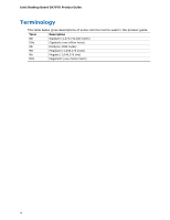
Intel Desktop Board DX79TO Product Guide Terminology The table below gives descriptions of some common terms used in the product guide. Term Description GB Gigabyte (1,073,741,824 bytes) GHz Gigahertz (one billion hertz) KB Kilobyte (1024 bytes) MB Megabyte (1,048,576 bytes) Mb Megabit - Intel DX79TO | Product Guide - Page 5
Operating Systems 11 Desktop Board Components 12 Processor ...14 System Memory 15 Memory Configurations 16 Intel® X79 Express Chipset 17 USB Support ...17 USB 3.0 ...17 USB 2.0 ...17 Serial ATA...17 Audio Subsystem 18 LAN Subsystem 18 Legacy I/O ...19 Expandability...19 BIOS ...20 Serial - Intel DX79TO | Product Guide - Page 6
Memory Update Utility 64 Recovering the BIOS 65 4 Configuring for RAID Using Intel® Rapid Storage Technology Configuring the BIOS 67 Creating Your RAID Set 67 Loading the Intel RST RAID Drivers and Software (Required for Microsoft Windows XP Installation 68 Setting Up a "RAID Ready" System - Intel DX79TO | Product Guide - Page 7
26 7. Location of the Diagnostic/Status LEDs 27 8. Installing the I/O Shield 33 9. Intel Desktop Board DX79TO Mounting Screw Hole Locations 34 10. Unlatch the Socket Levers 35 11. Open the Load Plate 36 12. Install the Processor 37 13. Close the Load Plate 38 14. Installing a Fan Heat Sink - Intel DX79TO | Product Guide - Page 8
Desktop Board DX79TO Product Guide Tables 1. Feature Summary 9 2. Intel Desktop Board DX79TO Components 13 3. LAN Connector LEDs 19 4. System Initialization LEDs 28 5. Status LEDs 29 6. Front Panel Audio Header Signal Names 48 7. Chassis Intrusion - Intel DX79TO | Product Guide - Page 9
[9.60 inches]) Support for Intel® Core™ i7 and Intel® Xeon® processors in the LGA2011 Manual memory overclocking (voltage, clock, and ratio) Intel® X79 Express Chipset consisting of the Intel® X79 Platform Controller Hub (PCH) Graphics Audio Expansion Capabilities Legacy I/O Support Support - Intel DX79TO | Product Guide - Page 10
to an IEEE 1394a header • Six Serial ATA (SATA) channels through the Intel X79 PCH: LAN Support BIOS ― Two onboard 6.0 Gb/s SATA channels (blue connectors) ― Four headers for processor, front, rear, and auxiliary fans) with selectable support in the BIOS for 3-wire fans • Support for the Platform - Intel DX79TO | Product Guide - Page 11
bit editions) • Microsoft Windows Vista Home Basic (64-bit and 32-bit editions) The Desktop Board provides minimal BIOS and driver support for the following operating systems: • Microsoft Windows* XP Home • Microsoft Windows XP Professional • Microsoft Windows XP Professional x64 Edition • Microsoft - Intel DX79TO | Product Guide - Page 12
Intel Desktop Board DX79TO Product Guide Desktop Board Components Figure 1 shows the approximate location of the major components on Intel Desktop Board DX79TO. Figure 1. Intel Desktop Board DX79TO Components 12 - Intel DX79TO | Product Guide - Page 13
socket R 12 V processor core voltage connector (2 x 4 pin) S DIMM 8 socket T DIMM 4 socket U DIMM 7 socket V DIMM 3 socket W Main power connector (2 x 12 pin) X Front chassis fan header Y Serial ATA connectors (6 Gb/s) Z Serial ATA connectors (3 Gb/s) AA Intel X79 Express Chipset - Intel DX79TO | Product Guide - Page 14
intel.com/products/motherboard/index.htm • Desktop Board Support http://www.intel.com/p/en_US/support?iid=hdr+support • Available configurations for Intel Desktop Board DX79TO • Supported processors http://ark.intel.com http://processormatch.intel.com • Chipset information http://www.intel.com - Intel DX79TO | Product Guide - Page 15
support for memory speeds above 1600 MHz • Full support for memory overclocking (see www.intel.com/support/motherboards/desktop/sb/CS-031689.htm for information on overclocking) • Support useful life of the system, memory, and processor; (ii) cause the processor and other system components to fail; ( - Intel DX79TO | Product Guide - Page 16
Desktop Board DX79TO Product Guide Memory Configurations The Intel Core i7 and Intel Xeon processors support the following types of memory organization: • Quad-channel (Interleaved) mode. Quad-channel mode offers the highest throughput for real world applications. • Tri-channel (Interleaved) mode - Intel DX79TO | Product Guide - Page 17
to the processor and the USB, SATA, LAN, PCI, and PCI Express interfaces. The PCH is the centralized controller for the board's I/O paths. Go to the following link for more information about the Intel X79 Express Chipset: http://developer.intel.com/products/chipsets/index.htm USB Support The Desktop - Intel DX79TO | Product Guide - Page 18
• CSMA/CD protocol engine • LAN connect interface between the Intel PCH and the LAN controllers • PCI bus power management • ACPI technology support • LAN wake capabilities Go to the following link for information about LAN software and drivers: http://www.intel.com/products/motherboard/index.htm 18 - Intel DX79TO | Product Guide - Page 19
wake up event interface • PCI power management support Expandability Intel Desktop Board DX79TO provides the following expansion capability: • Two PCI Express 3.0 x16 connectors. Operation at PCI Express 3.0 speeds requires a processor that supports the PCI Express 3.0 Specification. • Three PCI - Intel DX79TO | Product Guide - Page 20
Guide BIOS The BIOS provides the Power-On Self-Test (POST), the BIOS Setup program, and the PCI/PCI Express and IDE auto-configuration utilities. The BIOS is stored in the Serial Peripheral Interface (SPI) Flash device. The BIOS can be updated by following the instructions manual configuration - Intel DX79TO | Product Guide - Page 21
Back to BIOS Button Hardware Management The hardware management features of Intel Desktop Board DX79TO enable the board to be compatible with the Nuvoton* Legacy I/O Controller, which provides the following: • Processor and system ambient temperature monitoring • Monitoring of power supply voltages - Intel DX79TO | Product Guide - Page 22
Intel Desktop Board DX79TO Product Guide Chassis Intrusion The board supports a chassis security feature that detects with the Desktop Board requires an operating system that provides full ACPI support. Hardware Support Power Connectors ATX12V-compliant power supplies can turn off the computer power - Intel DX79TO | Product Guide - Page 23
input of the hardware monitoring and control device. • All fan headers support closed-loop fan control that can adjust the fan speed or switch the have a +12 V DC connection. The Desktop Board has a 4-pin processor fan header and three 4-pin chassis fan headers. LAN Wake Capabilities CAUTION - Intel DX79TO | Product Guide - Page 24
Intel Desktop Board DX79TO Product Guide +5 V Standby Power Indicator CAUTION If the AC power has been switched off and the standby power standby current requirements for the Desktop Board, refer to the Technical Product Specification at http://www.intel.com/products/motherboard/index.htm 1 24 - Intel DX79TO | Product Guide - Page 25
the PME# signal on the PCI bus is asserted, the computer wakes from an ACPI S3, S4, or S5 state. WAKE# Signal Wake-up Support When the WAKE# signal on the PCI Express bus is asserted, the computer wakes from an ACPI S3, S4, or S5 state. Wake from Consumer - Intel DX79TO | Product Guide - Page 26
Intel Desktop Board DX79TO Product Guide Figure 6. Onboard System Control Switches Power Switch The power button switch (see Figure 6, A) can be used to turn the desktop board on or off. This - Intel DX79TO | Product Guide - Page 27
Desktop Board Features System Initialization/ Status LEDs The Desktop Board provides LEDs that allow you to monitor your system's progress through initialization and the BIOS POST (see Figure 7). There are also other board status LEDs that allow you to monitor other system activities. Figure 7. - Intel DX79TO | Product Guide - Page 28
Intel Desktop Board DX79TO Product Guide System Initialization LEDs At initial power on, these button has been pressed. This LED will flash when the processor initialization activity starts. Then the LED will stay on when processor initialization is complete. This LED will flash when the memory - Intel DX79TO | Product Guide - Page 29
elevated temperature on the processor that could affect board performance. This LED indicates an elevated temperature in the processor voltage regulator circuit TPM, refer to the Trusted Platform Module (TPM) Quick Reference Guide included with the board. Speaker A speaker is mounted on the Desktop - Intel DX79TO | Product Guide - Page 30
Intel Desktop Board DX79TO Product Guide Battery A battery on the Desktop Board keeps the values in CMOS RAM and the clock current when the computer is turned off and disconnected from AC power. Go to page 56 for instructions on how to replace the battery. Real-Time Clock The Desktop Board has a - Intel DX79TO | Product Guide - Page 31
2 Installing and Replacing Desktop Board Components This chapter tells you how to: • Install the I/O shield • Install the Desktop Board • Install a processor • Install memory • Install and remove a PCI Express x16 card • Connect the Serial ATA cables • Connect to the internal headers and connectors - Intel DX79TO | Product Guide - Page 32
sharp corners on the chassis • Hot components (such as processors, voltage regulators, and heat sinks) • Damage to wires that could cause a short circuit Observe all warnings and cautions that instruct you to refer computer servicing to qualified technical personnel. Prevent Power Supply Overload Do - Intel DX79TO | Product Guide - Page 33
Installing and Replacing Desktop Board Components Installing the I/O Shield The Desktop Board comes with an I/O shield. When installed in the chassis, the shield blocks radio frequency transmissions, protects internal components from dust and foreign objects, and promotes correct airflow within the - Intel DX79TO | Product Guide - Page 34
Intel Desktop Board DX79TO Product Guide Installing the Desktop Board CAUTION Only qualified technical personnel computer can result in personal injury or equipment damage. Refer to your chassis manual for instructions on installing and removing the Desktop Board. Figure 9 shows the location of the - Intel DX79TO | Product Guide - Page 35
; the standby power LED should not be lit (see Figure 5 on page 24). Failure to do so could damage the processor and the board. To install a processor, follow these instructions: 1. Observe the precautions in "Before You Begin" on page 31. 2. Open the socket lever marked "OPEN 1st" by pushing the - Intel DX79TO | Product Guide - Page 36
Intel Desktop Board DX79TO Product Guide 4. Push down on the lever "OPEN 1st" (Figure 11, A) to lift the socket load plate as shown. Grasp the load plate and lift up to open it fully (Figure 11, B). Do not touch the socket contacts. Figure 11. Open the Load Plate 36 - Intel DX79TO | Product Guide - Page 37
socket as shown in Figure 12. Make sure the gold-colored triangle indicating pin 1 on the processor aligns with the triangle on the socket (Figure 12, A) before you lower the processor into place. Lower the processor (Figure 12, B) straight down without tilting or sliding it in the socket. Figure 12 - Intel DX79TO | Product Guide - Page 38
Intel Desktop Board DX79TO Product Guide 7. Close the load plate (Figure 13, A). After the load plate is closed, engage the socket lever labeled "CLOSE 1st" (Figure the socket cover; save it for possible future use. Always replace the socket cover if you remove the processor from the socket. 38 - Intel DX79TO | Product Guide - Page 39
fan heat sink to the Desktop Board, refer to the Intel boxed processor manual, Intel boxed thermal solution manual, or instructions third-party thermal solution providers. Connect the processor fan heat sink cable to the 4-pin processor fan header (see Figure 14). A fan with a 4-pin connector as - Intel DX79TO | Product Guide - Page 40
Desktop Board DX79TO Product Guide Installing and Removing Memory Intel Desktop board DX79TO has eight 240-pin DDR3 DIMM sockets DIMMs NOTE Using a DIMM with a voltage rating higher than 1.65 V may damage the processor. To install a DIMM, follow these steps: 1. Observe the precautions in "Before You - Intel DX79TO | Product Guide - Page 41
Installing and Replacing Desktop Board Components Figure 15. Installing a DIMM 4. Make sure the clips at either end of the DIMM socket(s) are pushed outward to the open position. 5. Holding the DIMM by the edges, remove it from its anti-static package. 6. Position the DIMM above the socket. Align - Intel DX79TO | Product Guide - Page 42
Intel Desktop Board DX79TO Product Guide Removing DIMMs To remove a DIMM, follow these steps: 1. install it in the PCI Express primary connector (Figure 16, A) for optimum performance. Follow these instructions to install a PCI Express x16 card: 1. Observe the precautions in "Before You Begin" on - Intel DX79TO | Product Guide - Page 43
Installing and Replacing Desktop Board Components Figure 16. Installing a PCI Express x16 Card Removing a PCI Express x16 Add-in Card Follow these instructions to remove a PCI Express x16 card from a connector: 1. Observe the precautions in "Before You Begin" on page 31. 2. Remove the screw (Figure - Intel DX79TO | Product Guide - Page 44
Intel Desktop Board DX79TO Product Guide Figure 17. Removing a PCI Express x16 Card Installing Linked PCI Express x16 Graphics Cards The Desktop Board supports . NOTE The installations steps that follow provide general instructions, for more complete installation and configuration information refer - Intel DX79TO | Product Guide - Page 45
with the SLI bridge (Figure 18, C) as shown. 6. Connect the monitor cable to the graphics card according to the manufacturer's instructions. Figure 18. Installing Linked PCI Express Graphics Cards For more complete installation and configuration information refer to the documentation supplied by the - Intel DX79TO | Product Guide - Page 46
Intel Desktop Board DX79TO Product Guide Connecting SATA Cables SATA cables support the Serial ATA protocol. Each cable can be used to connect one internal SATA drive to the Desktop Board. The blue connectors support SATA 6 Gb/s and lower transfer rates and the black connectors support SATA 3 Gb/s - Intel DX79TO | Product Guide - Page 47
the internal headers or connectors, observe the precautions in "Before You Begin" on page 31. Figure 20 shows the location of the internal headers on Intel Desktop Board DX79TO. Figure 20. Internal Headers 47 - Intel DX79TO | Product Guide - Page 48
Intel Desktop Board DX79TO Product Guide Front Panel Audio Header Figure 20, A shows the location of the front panel audio header. Table 6 shows the pin assignments and signal names for the - Intel DX79TO | Product Guide - Page 49
Installing and Replacing Desktop Board Components Consumer IR (CIR) Headers The Desktop Board has two CIR headers: the input or receiver header (Figure 20, F) and the output or emitter header (Figure 20, D). The receiver header consists of a filtered translated infrared input compliant with - Intel DX79TO | Product Guide - Page 50
Intel Desktop Board DX79TO Product Guide USB 2.0 Headers Figure 20, E shows the location of the USB 2.0 headers. Table 11 shows the pin assignments and signal names for each USB 2.0 header. Each - Intel DX79TO | Product Guide - Page 51
green LED 2 No pin 3 Front panel yellow LED In/Out Out Out Connecting to the Audio System After installing the RealTek audio driver from the Intel® Express Installer DVD, the multi-channel audio feature can be enabled. Figure 21 shows the back panel audio connectors. The default connector - Intel DX79TO | Product Guide - Page 52
Intel Desktop Board DX79TO Product Guide Connecting Chassis Fan and Power Supply Cables Connecting Chassis Fan Cables Connect chassis fan cables to the chassis fan headers on the Desktop Board. Figure 22 shows the location of the chassis fan headers. The board supports 4-wire and 3-wire fans. Figure - Intel DX79TO | Product Guide - Page 53
with 2 x 10 connectors. Figure 23. Connecting Power Supply Cables 1. Observe the precautions in "Before You Begin" on page 31. 2. Connect the 12 V processor core voltage power supply cable to the 2 x 4 pin connector (Figure 23, A). 3. Connect the main power supply cable to the 2 x 12 pin connector - Intel DX79TO | Product Guide - Page 54
Intel Desktop Board DX79TO Product Guide Setting the BIOS Configuration Jumper NOTE Always turn off the power to the computer before moving the jumper. Moving the jumper with the power on - Intel DX79TO | Product Guide - Page 55
Installing and Replacing Desktop Board Components Table 14. Jumper Settings for the BIOS Setup Program Modes Mode Normal (default) (1-2) Configure (2-3) Recovery (None) Description The BIOS uses the current configuration and passwords for booting. After the Power-On Self-Test (POST) runs, the - Intel DX79TO | Product Guide - Page 56
Intel Desktop Board DX79TO Product Guide Replacing the Battery A coin-cell battery (CR2032) powers the real-time clock and CMOS memory. When the computer is not plugged into a wall socket, the - Intel DX79TO | Product Guide - Page 57
substituída por um tipo de bateria incorreto. As baterias devem ser recicladas nos locais apropriados. A eliminação de baterias usadas deve ser feita de acordo com as regulamentações ambientais da região. AŚCIAROŽZNA 57 - Intel DX79TO | Product Guide - Page 58
Intel Desktop Board DX79TO Product Guide UPOZORNÌNÍ V případě výměny baterie za nesprávný druh může dojít k výbuchu. Je-li to možné, baterie by měly být recyklovány. Baterie je třeba zlikvidovat v souladu s místní - Intel DX79TO | Product Guide - Page 59
Installing and Replacing Desktop Board Components UPOZORNENIE Ak batériu vymeníte za nesprávny typ, hrozí nebezpečenstvo jej výbuchu. Batérie by sa mali podľa možnosti vždy recyklovať. Likvidácia použitých batérií sa musí vykonávať v súlade s miestnymi predpismi na ochranu životného prostredia. - Intel DX79TO | Product Guide - Page 60
Intel Desktop Board DX79TO Product Guide 60 - Intel DX79TO | Product Guide - Page 61
Installing and Replacing Desktop Board Components To replace the battery, follow these steps: 1. Observe the precautions in "Before You Begin" (see page 31). 2. Turn off all peripheral devices connected to the computer. Disconnect the computer's power cord from the AC power source (wall outlet or - Intel DX79TO | Product Guide - Page 62
Intel Desktop Board DX79TO Product Guide 62 - Intel DX79TO | Product Guide - Page 63
. To update the BIOS with the Intel Express BIOS Update utility: 1. Go to the Intel World Wide Web site Download Center at http://downloadcenter.intel.com/ 2. Navigate to the DX79TO page. runs the update program. 6. Follow the instructions provided in the dialog boxes to complete the BIOS update. 63 - Intel DX79TO | Product Guide - Page 64
Intel Desktop Board DX79TO Product Guide Updating the BIOS Using the F7 Function Key To use this BIOS your computer supplier or by navigating to the Intel Desktop Board DX79TO page on the Intel World Wide Web site Download Center at http://downloadcenter.intel.com. On the DX79TO page, click on the - Intel DX79TO | Product Guide - Page 65
.intel.com. On the Intel Desktop Board DX79TO page, click on the "BIOS Update" link and then select the Recovery BIOS Update file. NOTE For more information about updating the Intel Desktop Board BIOS or recovering from a BIOS update failure, go to http://support.intel.com/support/motherboards - Intel DX79TO | Product Guide - Page 66
Intel Desktop Board DX79TO Product Guide 66 - Intel DX79TO | Product Guide - Page 67
operating system and SATA hard drives. This section describes how to: • Configure the BIOS for RAID • Create a RAID Set • Load the Intel RST RAID Drivers and Software (required for Microsoft Windows XP installation only) • Create a "RAID Ready System" Configuring the BIOS 1. Assemble your system and - Intel DX79TO | Product Guide - Page 68
and install all necessary drivers. 4. Install the Intel Rapid Storage Console software via the Intel Express Installer DVD included with your Desktop Board or after downloading it from the Internet at http://support.intel.com/support/motherboards/desktop/. The Intel Rapid Storage Console software - Intel DX79TO | Product Guide - Page 69
A Error Messages and Indicators Intel Desktop Board DX79TO reports POST errors in three ways: • By power LED to blink an error message indicating the problem (see Table 15). Table 15. BIOS Beep Codes Type Pattern Processor One 0.5 second beep when the CPU initialization process - Intel DX79TO | Product Guide - Page 70
Intel Desktop Board DX79TO Product Guide BIOS Error Messages When a recoverable error occurs during the POST, the BIOS displays an error message describing the problem. Table 17 gives an explanation of the BIOS error messages. Table 17. BIOS Error Messages Error Message - Intel DX79TO | Product Guide - Page 71
Error Messages and Indicators Port 80h POST Codes During the POST, the BIOS generates diagnostic progress codes (POST codes) to I/O port 80h. If the POST fails, execution stops and the last POST code generated is left at port 80h and displayed on the Desktop Board's seven-segment LED display shown - Intel DX79TO | Product Guide - Page 72
Intel Desktop Board DX79TO Product Guide Table addresses Wake up all APS Initialize NEM Pass entry point of the PEI core 11 12 13 14 15 16 17, 18 19, 1A 1B, init driver SMBUS driver init Entry/Exit to SMBUS execute read/write Entry/Exit to CK505 programming Entry/Exit to PEI overclock programming - Intel DX79TO | Product Guide - Page 73
error, start with PIC 60-6F E4 E7 E8 E9 EB Boot Device Selection (BDS) BDS driver entry Entered DXE phase Waiting for user input Checking password Entering BIOS setup Calling legacy option ROMs 90 Runtime Phase/EFI Operating System Boot F8 EFI boot service ExitBootServices F9 EFI runtime - Intel DX79TO | Product Guide - Page 74
Intel Desktop Board DX79TO Product Guide 74 - Intel DX79TO | Product Guide - Page 75
Caution There is insufficient space on this Desktop Board to provide instructions for replacing and disposing of the Lithium ion coin cell battery the chassis near the battery. A suitable caution label is included with Intel Desktop Board DX79TO. CAUTION Risk of explosion if the battery is replaced - Intel DX79TO | Product Guide - Page 76
Board DX79TO Product Guide European Union Declaration of Conformity Statement We, Intel Corporation, declare under our sole responsibility that the product Intel® Desktop Board DX79TO is in conformity with all applicable essential requirements necessary for CE marking, following the provisions - Intel DX79TO | Product Guide - Page 77
. Please consult http://intel.com/intel/other/ehs/product_ecology for the details of this program, including the scope of covered products, available locations, shipping instructions, terms and conditions, etc Intel Product Recycling Program http://intel.com/intel/other/ehs/product_ecology 77 - Intel DX79TO | Product Guide - Page 78
ées. Visitez la page Web http://intel.com/intel/other/ehs/product_ecology pour en savoir plus sur ce programme, à savoir les produits concernés, les adresses disponibles, les instructions d'expédition, les conditions générales, etc. http://intel.com/intel/ot her/ehs/product_ecology Malay Sebagai - Intel DX79TO | Product Guide - Page 79
dos produtos cobertos, os locais disponíveis, as instruções de envio, os termos e condições, etc. Russian Intel Intel (Product Recycling Program Intel http://intel.com/intel/other/ehs/product_ecology Türkçe Intel, çevre sorumluluğuna bağımlılığının bir parçası olarak, perakende tüketicilerin - Intel DX79TO | Product Guide - Page 80
Board DX79TO Product Guide China RoHS Intel Desktop Board DX79TO is a China RoHS-compliant product. The China Ministry of Information Industry (MII) stipulates that a material Self Declaration Table (SDT) must be included in a product's user documentation. The SDT for Intel Desktop Board DX79TO - Intel DX79TO | Product Guide - Page 81
For questions related to the EMC performance of this product, contact: Intel Corporation, 5200 N.E. Elam Young Parkway, Hillsboro, OR 97124 1-800-628- energy and, if not installed and used in accordance with the instructions, may cause harmful interference to radio communications. However, there is - Intel DX79TO | Product Guide - Page 82
Intel Desktop Board DX79TO Product Guide radio or television reception help. Any changes or modifications to the equipment not expressly approved by Intel Corporation could void the user's authority to operate the equipment. Tested to comply use the equipment according to the instruction manual. 82 - Intel DX79TO | Product Guide - Page 83
, as applicable, have passed Class B EMC testing and are marked accordingly. Pay close attention to the following when reading the installation instructions for the host chassis, power supply, and other modules: • Product certifications or lack of certifications • External I/O cable shielding and - Intel DX79TO | Product Guide - Page 84
Desktop Board DX79TO Product Guide Product Certifications Board-Level Certifications Intel Desktop Board DX79TO has the regulatory compliance Friendly Use Period Logo: This is an example of the symbol used on Intel Desktop Boards and associated collateral. The color of the mark may vary depending - Intel DX79TO | Product Guide - Page 85
with safety requirements. The Industry Canada statement on page 82 of this product guide demonstrates compliance with Canadian EMC regulations. ENERGY STAR*, e-Standby, and ErP For information about ENERGY STAR requirements and recommended configurations, go to http://www.intel.com/go/energystar. 85 - Intel DX79TO | Product Guide - Page 86
Intel Desktop Board DX79TO Product Guide 86
-
 1
1 -
 2
2 -
 3
3 -
 4
4 -
 5
5 -
 6
6 -
 7
7 -
8
-
9
-
10
-
11
-
12
-
13
-
14
-
15
-
16
-
17
-
18
-
19
-
20
-
21
-
22
-
23
-
24
-
25
-
26
-
27
-
28
-
29
-
30
-
31
-
32
-
33
-
34
-
35
-
36
-
37
-
38
-
39
-
40
-
41
-
42
-
43
-
44
-
45
-
46
-
47
-
48
-
49
-
50
-
51
-
52
-
53
-
54
-
55
-
56
-
57
-
58
-
59
-
60
-
61
-
62
-
63
-
64
-
65
-
66
-
67
-
68
-
69
-
70
-
71
-
72
-
73
-
74
-
75
-
76
-
77
-
78
-
79
-
80
-
81
-
82
-
83
-
84
-
85
-
86
 |
 |
Intel
®
Desktop Board DX79TO
Product Guide
Order Number:
G44000-001