Intel H2000JF System Service Guide
Intel H2000JF Manual
 |
View all Intel H2000JF manuals
Add to My Manuals
Save this manual to your list of manuals |
Intel H2000JF manual content summary:
- Intel H2000JF | System Service Guide - Page 1
Intel® Server System H2000JF Family Service Guide A Guide for Technically Qualified Assemblers of Intel® Identified Subassemblies/Products Order Number: G42283-004 - Intel H2000JF | System Service Guide - Page 2
trademarks or registered trademarks of Intel Corporation or its subsidiaries in the United States and other countries. * Other names and brands may be claimed as the property of others. Copyright © 2012 Intel Corporation. All Rights Reserved. ii Intel® Server System H2000JF Family Service Guide - Intel H2000JF | System Service Guide - Page 3
Server Deployment Toolkit 3.0 CD y/o en http://www.intel.com/support/motherboards/server/sb/cs-010770.htm. http://www.intel.com/support/motherboards/server/sb/cs-010770.htm 上的 Intel® Server Boards and Server Chassis Safety Information(《Intel Intel® Server System H2000JF Family Service Guide - Intel H2000JF | System Service Guide - Page 4
contacts inside the jumper, causing intermittent problems with the function controlled by that jumper. Take care to grip with, but not squeeze, the pliers or other tool you use to remove a jumper, or you may bend or break the pins on the board. iv Intel® Server System H2000JF Family Service Guide - Intel H2000JF | System Service Guide - Page 5
you may need, troubleshooting information, and instructions on how to add and replace components on the Intel® Server System H2000JF family products. For the latest revision of this manual, go to http://www.intel.com/p/en_US/support. Table 1. Intel® Server System H2000JF Family Product List - Intel H2000JF | System Service Guide - Page 6
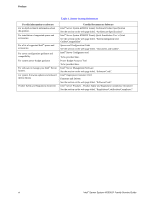
DVD Firmware and Drivers See the section on the web page titled, "Software/Code". Intel® Server Products - Product Safety and Regulatory Compliance Document See the section on the web page titled, "Regulations/Certification/Compliance". vi Intel® Server System H2000JF Family Service Guide - Intel H2000JF | System Service Guide - Page 7
and Installing Processor 22 Removing Processor Heatsink(s 22 Installing the Processor ...23 Installing Processor Heatsink(s 25 Removing the Processor ...26 Installing and Removing Memory ...26 Installing Memory ...26 Removing Memory ...27 Intel® Server System H2000JF Family Service Guide vii - Intel H2000JF | System Service Guide - Page 8
from Rack 55 3 Server Utilities ...57 Using the BIOS Setup Utility...57 Starting Setup ...57 Setup Navigation Keyboard Commands 57 Setup Screen Menu Selection Bar 58 BIOS Setup Utility Screens ...58 Map of Screens and Functionality 59 viii Intel® Server System H2000JF Family Service Guide - Intel H2000JF | System Service Guide - Page 9
Voltages 61 System Environmental Specifications 61 Appendix B: Regulatory and Compliance Information 63 Appendix C: LED Decoder ...64 Appendix D: Getting Help...70 Warranty Information ...70 Appendix E: Intel® Server Issue Report Form 71 Intel® Server System H2000JF Family Service Guide ix - Intel H2000JF | System Service Guide - Page 10
Processor Heatsink 23 Figure 31. Installing Processor - Open the Socket Lever 23 Figure 32. Installing Processor - Open the Load Plate 24 Figure 33. Installing Processor - Install the Processor 24 Figure 34. Installing Processor Assembly 31 x Intel® Server System H2000JF Family Service Guide - Intel H2000JF | System Service Guide - Page 11
the NPD Board ...41 Figure 64. Removing the Node Fan Set 41 Figure 65. Installing the Server Board...42 Figure 66. Removing the 2.5" Backplane Board 43 Figure 67. Align the Backplane to the 56 Figure 90. Diagnostic LED Placement Diagram 64 Intel® Server System H2000JF Family Service Guide xi - Intel H2000JF | System Service Guide - Page 12
Bar 57 Table 7. Screen Map ...59 Table 8. CRPS Input Voltage...61 Table 9. CRPS Output Voltage ...61 Table 10. System Environmental Limits Summary 61 Table 11. POST Progress Code LED Example 65 Table 12. Diagnostic LED POST Code Decoder 65 xii Intel® Server System H2000JF Family Service Guide - Intel H2000JF | System Service Guide - Page 13
List of Tables Intel® Server System H2000JF Family Service Guide xiii - Intel H2000JF | System Service Guide - Page 14
Support for one or two Intel® Xeon® processors E5-2600 product family with a Thermal Design Power (TDP) of up to 135 W(8-core and 6-core) and below, or 80W(4-core) and below. Eight DIMM slots - 1 DIMMs/Channel - 4 memory channels per processor. Intel® Server System H2000JF Family Service Guide - Intel H2000JF | System Service Guide - Page 15
port SATA connectors (on baseboard and bridge board) capable of supporting up to 6 GB/sec. SCU0 4-port up to 3 GB/sec SAS/SATA through bridge board. Intel® RAID C600 Upgrade Key support providing optional expanded SATA/SAS RAID capabilities. 2 Intel® Server System H2000JF Family Service Guide - Intel H2000JF | System Service Guide - Page 16
B Compute Node 1 Tray C Compute Node 4 Tray F HDD bays with Hot Swap Backplane G Upper and Lower Power Distribution Boards D Compute Node 2 Tray H Front Control Panel Figure 2. Intel® Server System H2000JF Overview (H2312JF as demonstrated) Intel® Server System H2000JF Family Service Guide 3 - Intel H2000JF | System Service Guide - Page 17
Hard Disk Drive array based on backplane controller design. Below are schemes for HDD array in correspondent to Compute Node. Figure 6. HDD Array Scheme on Intel® Server System H2312JF 4 Intel® Server System H2000JF Family Service Guide - Intel H2000JF | System Service Guide - Page 18
C System Status LED D Network Link/Activity LED Figure 8. Front Panel Options Back Panel Compute Node back panel scheme is shown below : Description A NIC port 1 (RJ45) B NIC port 2 (RJ45) Description E Status LED F Dual port USB connector Intel® Server System H2000JF Family Service Guide 5 - Intel H2000JF | System Service Guide - Page 19
Port 1 AC CPU 2 N USB x2 V Riser Slot1 with PCIe Gen3 x16 AD O Debug connector W Integrated BMC P Status and ID LED X Storage Upgrade key Figure 10. Server Board Connector and Component Locations 2x3 PWR connector (2 total) 6 Intel® Server System H2000JF Family Service Guide - Intel H2000JF | System Service Guide - Page 20
several servers. The ID LED is off by default, and blue when activated by button or software. The System Status LED on the front and back panels shows the overall health of the system (green, blinking green, blinking amber, amber, and off). Intel® Server System H2000JF Family Service Guide 7 - Intel H2000JF | System Service Guide - Page 21
Server System Features System Recovery Jumpers Jumper Name J6B1: BMC Force Update jumper J1E2: ME Force Update J1E3: Password Clear Jumper Position 1-2 2-3 ME in force update mode Normal mode, password in protection BIOS password is cleared 8 Intel® Server System H2000JF Family Service Guide - Intel H2000JF | System Service Guide - Page 22
13. Front View of System Bezel Hot-Swap SAS/SATA Backplane The Hot-Swap SAS/SATA backplane serves as an interface between the mother board and the system drives. The following diagrams show the location for each connector found on the backplane. Intel® Server System H2000JF Family Service Guide 9 - Intel H2000JF | System Service Guide - Page 23
Server System Features 12 x 3.5-inch Hard Drive Backplane A SATA/SAS connectors for Node 1 B SATA/SAS connectors for Node 2 C SATA 2Blade Compute Node Power connector for Node 2 Figure 15. 12 x 3.5-inch Hard Drive Backplane Components (Rear View) 10 Intel® Server System H2000JF Family Service Guide - Intel H2000JF | System Service Guide - Page 24
16 x 2.5-inch Hard Drive Backplane Server System Features A SATA/SAS connectors for Node 1 B SATA/SAS connectors for Node 2 C SATA/SAS connectors connector for Node 2, 4 Figure 17. 16 x 2.5-inch Hard Drive Backplane Components (Rear View) Intel® Server System H2000JF Family Service Guide 11 - Intel H2000JF | System Service Guide - Page 25
Redirection allowing USB devices attached to the remote system to be used on the managed server. For instructions on installing the Intel® Remote Management Module 4 Lite, see Installing and Removing the Intel® Remote Management Module 4 Lite. 12 Intel® Server System H2000JF Family Service Guide - Intel H2000JF | System Service Guide - Page 26
beginning of this manual. Note: Whenever you service the system, you must first power down the server and unplug all peripheral Intel® Server System H2000JF is shown for illustration purpose. Server components with the product family are identical. Intel® Server System H2000JF Family Service Guide - Intel H2000JF | System Service Guide - Page 27
cable connection Figure 18. Cable Routing inside Node tray Removing and Installing the Front Bezel Removing the Front Bezel If your system includes a front bezel, follow these steps to remove the front bezel: 1. Unlock the bezel if it is locked. 14 Intel® Server System H2000JF Family Service Guide - Intel H2000JF | System Service Guide - Page 28
to remove the top cover to add or replace components (backplane, main power cables, power distribution board) inside of the server. Before removing the top cover, power down the server and unplug all peripheral devices and the power cable(s). Intel® Server System H2000JF Family Service Guide 15 - Intel H2000JF | System Service Guide - Page 29
System Top Cover Installing the System Cover 1. Place system cover onto the chassis and slide forward to engage recessed edge at front of cover (see letter A). 2. Rotate the front end of top cover down to position and fix screws (see letter B). 16 Intel® Server System H2000JF Family Service Guide - Intel H2000JF | System Service Guide - Page 30
Hardware Installations and Upgrades Figure 22. Installing the System Cover Removing and Installing the Compute Node Tray Each Compute Node tray is identical in the Installing the Node Tray 1. Align and slide in the Node Tray to the chassis rail. Intel® Server System H2000JF Family Service Guide 17 - Intel H2000JF | System Service Guide - Page 31
sound. Figure 24. Installing the Node Tray Removing and Installing the Redundant Power Supply Unit The system equipped with two CRPS for redundancy. Each of them can be hot swappable. Removing the Power locks in position with a "tick" sound. 18 Intel® Server System H2000JF Family Service Guide - Intel H2000JF | System Service Guide - Page 32
airflow within the server system. Removing the Air Duct 1. Press and hold both left and right side of rear air duct (see letter A). 2. Slowly lift the rear end of air duct (see letter B). 3. Rotate the airduct more than 45 degrees and pull out. Intel® Server System H2000JF Family Service Guide 19 - Intel H2000JF | System Service Guide - Page 33
of air duct to chassis fixture (see letter A). 2. Lower down the rear end of the air duct to fix with a "tick" sound (see letter B). 20 Intel® Server System H2000JF Family Service Guide - Intel H2000JF | System Service Guide - Page 34
slot 1 is installed, the transparent Mylar* attached to the air duct must be installed in between add-in card and rear IO bracket for isolation. Intel® Server System H2000JF Family Service Guide 21 - Intel H2000JF | System Service Guide - Page 35
material. Use gloves to avoid sharp edges. Removing Processor Heatsink(s) The heatsink is attached to the server board/processor socket with captive fasteners. Using a #2 Phillips* are loosened. 3. Lift the heatsink straight up (see letter C). 22 Intel® Server System H2000JF Family Service Guide - Intel H2000JF | System Service Guide - Page 36
away from the socket to release it (see letter A). Repeat the steps to release the lever on the other side (see letter B). Figure 31. Installing Processor - Open the Socket Lever Intel® Server System H2000JF Family Service Guide 23 - Intel H2000JF | System Service Guide - Page 37
DO NOT DROP processor into the socket! 4. Remove the Cover. Press the cover to remove it. Save the protective cover. Figure 34. Installing Processor - Remove the Cover 5. Close the Load Plate. Carefully lower the load plate over the processor. 24 Intel® Server System H2000JF Family Service Guide - Intel H2000JF | System Service Guide - Page 38
levers in the order as shown. Figure 36. Installing Processor - Latch the Locking Lever Installing Processor Heatsink(s) Note: The processor heatsink for CPU1 and CPU2 is different. FXXCA91X91HS ( a maximum of 8 inch-lbs torque (see letter E). Intel® Server System H2000JF Family Service Guide 25 - Intel H2000JF | System Service Guide - Page 39
socket lever, see Figure 31. 3. Open the load plate, see Figure 32. 4. Remove the processor. Installing and Removing Memory Installing Memory 1. Locate the DIMM sockets. Make sure the clips at either the clips are firmly in place (see letter E). 26 Intel® Server System H2000JF Family Service Guide - Intel H2000JF | System Service Guide - Page 40
empty drive bays must be occupied by carriers with blank plastic drive provided to maintain proper system cooling. Installing a Hard Disk Drive into 3.5" Hard Drive Carrier 1. Remove the four screws the lever to lock it into place (see letter B). Intel® Server System H2000JF Family Service Guide 27 - Intel H2000JF | System Service Guide - Page 41
into the chassis, then push in the lever to lock it into place (see letter F). Figure 42. Installing Hard Disk Drive - Inserting 2.5" HDD Assembly 28 Intel® Server System H2000JF Family Service Guide - Intel H2000JF | System Service Guide - Page 42
(letter B). Figure 44. Plug in PCIe Add-in Card 3. Plug in the assembly to riser slot on baseboard (see letter D) and fasten the screw (letter E). Intel® Server System H2000JF Family Service Guide 29 - Intel H2000JF | System Service Guide - Page 43
carrier assembly (letter A) by loosening the screws (letter B and C). Figure 46. Removing IOM Assembly 2. Remove PCIe riser assembly (letter B) by loosening the screw (letter A). 30 Intel® Server System H2000JF Family Service Guide - Intel H2000JF | System Service Guide - Page 44
riser and carrier assembly The IOM riser and carrier assembly are provided as optional accessory. This assembly provides the support to Intel® RMM4 dedicated NIC port and IO module. 1. Install IO module to IOM carrier using screw in letter B. Intel® Server System H2000JF Family Service Guide 31 - Intel H2000JF | System Service Guide - Page 45
in the whole IOM assembly into riser slot 2 on baseboard (letter F) and fasten with screws (letter G and E). Figure 51. Fastening the Assembly in Chassis 32 Intel® Server System H2000JF Family Service Guide - Intel H2000JF | System Service Guide - Page 46
slot (letter D) and remove rear bracket (letter E). Figure 53. Removing IOM Assembly from Chassis 3. Release screw in letter G, and remove IO module from assembly (letter F). Intel® Server System H2000JF Family Service Guide 33 - Intel H2000JF | System Service Guide - Page 47
Locate the RMM4 Lite connector next to RISER SLOT_2. Pick up the Intel® RMM4 Lite module carefully. Match the alignment pin of the module and the connector on the server board, and press to install. Figure 55. Installing the Intel® RMM4 Lite 34 Intel® Server System H2000JF Family Service Guide - Intel H2000JF | System Service Guide - Page 48
5, 10 RKSAS4 Green 4 Port SAS with Intel® ESRT2 RAID 0, 1, 10 and Intel® RSTe RAID 0, 1, 10 RKSAS4R5 Yellow 4 Port SAS with Intel® ESRT2 RAID 0, 1, 5, 10 and Intel® RSTe RAID 0, 1, 10 Figure 56. Installing the Intel® Storage Upgrade Key Intel® Server System H2000JF Family Service Guide 35 - Intel H2000JF | System Service Guide - Page 49
(letter A) on the bridge board. 2. Straightly lift up bridge board to remove from the server board. Figure 57. Removing the Bridge Board Installing the Bridge Board 1. Attach the plastic holder four screws (see letter C) to the tray side wall. 36 Intel® Server System H2000JF Family Service Guide - Intel H2000JF | System Service Guide - Page 50
letter B of Figure 59. 3. Align the plastic clip at the front of the board, see letter A. 4. Fasten the bridge board with six screws, see letter C. Intel® Server System H2000JF Family Service Guide 37 - Intel H2000JF | System Service Guide - Page 51
RAID/SAS Controller 1. Use designated MiniSAS cable shipped with Spare Bridge Board. 2. Plug in Mini SAS cable to the RAID/SAS Controller Card firstly. 38 Intel® Server System H2000JF Family Service Guide - Intel H2000JF | System Service Guide - Page 52
Hardware Installations and Upgrades Figure 60. Connecting Mini SAS Cable to RAID/SAS Controller 3. Then plug in MiniSAS cable to the Mini SAS port on the bridge board. Intel® Server System H2000JF Family Service Guide 39 - Intel H2000JF | System Service Guide - Page 53
the NPD Board 1. Place the NPD board into the tray base. 2. Secure the NPD board with four screws. 3. Connect all cables between NPD board and server board. 40 Intel® Server System H2000JF Family Service Guide - Intel H2000JF | System Service Guide - Page 54
the Fan Set 1. Disconnect the fan cables from the NPD board. 2. Remove the fan set from the dock. Figure 64. Removing the Node Fan Set Intel® Server System H2000JF Family Service Guide 41 - Intel H2000JF | System Service Guide - Page 55
the fan set cable to the connector on the NPD board. Figure 65. Installing the Server Board Installing and Removing the 2.5" Backplane Board Removing the 2.5" Backplane Board 1. Disconnect all straightly to remove from the chassis holder. 42 Intel® Server System H2000JF Family Service Guide - Intel H2000JF | System Service Guide - Page 56
the 2.5" Backplane Board Installing the Server Board 1. Place the backplane board into the clamps on chassis base. Figure 67. Align the Backplane to the Clamps on the Chassis Base 2. Secure the backplane board with four screws (see letter B). Intel® Server System H2000JF Family Service Guide 43 - Intel H2000JF | System Service Guide - Page 57
board. 2. Remove the three screws to release the backplane board from chassis. 3. Straightly lift up the backplane board to remove from the chassis holder. 44 Intel® Server System H2000JF Family Service Guide - Intel H2000JF | System Service Guide - Page 58
the 2.5" Backplane Board Installing the Server Board 1. Place the backplane board into the clamps on chassis base. Figure 70. Align the Backplane to the Clamps on the Chassis Base 2. Secure the backplane board with three screws (see letter B). Intel® Server System H2000JF Family Service Guide 45 - Intel H2000JF | System Service Guide - Page 59
of upper PDB board and remove it. Figure 72. Removing the Upper PDB 4. Release the four screws of lower PDB board and remove it. 46 Intel® Server System H2000JF Family Service Guide - Intel H2000JF | System Service Guide - Page 60
Hardware Installations and Upgrades Figure 73. Removing the Lower PDB Installing the PDB 1. Remove top cover and power supply units from chassis. 2. Install the lower PDB first and secure with four screws. Intel® Server System H2000JF Family Service Guide 47 - Intel H2000JF | System Service Guide - Page 61
. 4. Install the upper PDB and secure with four screws. Figure 75. Installing the Upper PDB 5. Connect power cables and PMBus* cable to upper PDB. 48 Intel® Server System H2000JF Family Service Guide - Intel H2000JF | System Service Guide - Page 62
ohjeiden mukaisesti. 1. Locate the battery on the server board. 2. Gently press the metal clip as shown to release the battery (see letter A). 3. Remove the battery from the plastic socket (see letter B). Figure 76. Replacing the Backup Battery Intel® Server System H2000JF Family Service Guide 49 - Intel H2000JF | System Service Guide - Page 63
. Figure 78. Disconnecting Control Panel Cable 3. Loose and remove two screws from back of control panel board, so the board can be removed out. 50 Intel® Server System H2000JF Family Service Guide - Intel H2000JF | System Service Guide - Page 64
Installing Front Control Panel Board 1. Install front control panel board to panel shell. Figure 80. Installing Control Panel Board 2. Connect cable to front panel board. Intel® Server System H2000JF Family Service Guide 51 - Intel H2000JF | System Service Guide - Page 65
Control Panel Assembly to Rack Handle Rack Mounting the Chassis Intel® AXXELVRAIL Rail Kit Intel® AXXELVRAIL is a half extension value rail kit, which is bundled with H2000JF chassis. The rail kit can hold a chassis of maximum 130lb/59kg. 52 Intel® Server System H2000JF Family Service Guide - Intel H2000JF | System Service Guide - Page 66
. Mounting the Chassis on the Rack The slide rail kit, which is bundled with Intel® Server System H2000JF family, is packed in the same shipping box together with the chassis. Based on on the rack: 1. Preparation before the slide installation. Intel® Server System H2000JF Family Service Guide 53 - Intel H2000JF | System Service Guide - Page 67
Hardware Installations and Upgrades Figure 84. Removing the Inner Member from Slides 2. Install the slides to the rack. Figure 85. Installing Slides to the Rack 54 Intel® Server System H2000JF Family Service Guide - Intel H2000JF | System Service Guide - Page 68
87. Installing the Chassis to Rack Removing the Chassis from Rack Follow the below steps to remove the chassis from the rack. 1. Extend the slides. Intel® Server System H2000JF Family Service Guide 55 - Intel H2000JF | System Service Guide - Page 69
Hardware Installations and Upgrades Figure 88. Extending the Slides 2. Remove the Inner Member from the Chassis. Figure 89. Removing the Chassis from Rack 56 Intel® Server System H2000JF Family Service Guide - Intel H2000JF | System Service Guide - Page 70
Setup Utility options, which is used to change server configuration defaults. You can run BIOS Setup with or without an operating system being present. Starting Setup To enter the BIOS item must then be activated by pressing the key. Intel® Server System H2000JF Family Service Guide 57 - Intel H2000JF | System Service Guide - Page 71
following sections describe the screens available in the BIOS Setup utility for the configuration of the server platform. For each of these screens, there is an image of the screen with text is a hyperlink to its corresponding Field Description. 58 Intel® Server System H2000JF Family Service Guide - Intel H2000JF | System Service Guide - Page 72
Screens Third Level Screens Advanced Screen (Tab) Processor Configuration Memory Configuration Memory RAS and Performance Configuration Mass Storage Controller Configuration PCI Configuration Serial Port Configuration Intel® Server System H2000JF Family Service Guide 59 - Intel H2000JF | System Service Guide - Page 73
Acoustic and Performance Configuration Console Redirection System Information BMC LAN Configuration CDROM Option Hard Disk Order Floppy Option Network Device Order BEV Device Order Add EFI Boot Option Delete EFI Boot Option Third Level Screens 60 Intel® Server System H2000JF Family Service Guide - Intel H2000JF | System Service Guide - Page 74
, velocity change 205 inches/second (80 lbs to < 100 lbs) Shock, packaged Non-palletized free fall in height 18 inches (80 lbs to < 100 lbs) Intel® Server System H2000JF Family Service Guide 61 - Intel H2000JF | System Service Guide - Page 75
Vibration, unpackaged 5 Hz to 500 Hz, 2.20 g RMS random ESD +/-12 KV except I/O port +/- 8 KV per Intel® Environmental Test Specification. System Cooling Requirement in BTU/Hr 1200 Watt Max - 4095 BTU/hour 1600 Watt Max - 5459 BTU/hour 62 Intel® Server System H2000JF Family Service Guide - Intel H2000JF | System Service Guide - Page 76
B: Regulatory and Compliance Information Please refer to the Server Products Regulatory and Safety document for the product regulatory compliance reference. The document can be downloaded from http://www.intel.com/p/en_US/support/server/. Intel® Server System H2000JF Family Service Guide 63 - Intel H2000JF | System Service Guide - Page 77
the POST Code. Diagnostic LEDs are found on the back edge of the server board. To assist in troubleshooting a system hang during the POST process, the Diagnostic LEDs can be used to identify Link LED Figure 90. Diagnostic LED Placement Diagram 64 Intel® Server System H2000JF Family Service Guide - Intel H2000JF | System Service Guide - Page 78
or Memory Link Training failure 0xE8h 1 1 1 0 1 0 0 0 No memory available (system halted) 0xE9h 1 1 1 0 1 0 0 1 Unsupported or invalid DIMM configuration (system halted) 0xEAh 1 1 1 0 1 0 1 0 DIMM training sequence failed (system halted) Intel® Server System H2000JF Family Service Guide 65 - Intel H2000JF | System Service Guide - Page 79
of Integrated Memory Controller 0xBEh 1 0 1 1 1 1 1 0 Memory Initialization of Integrated Memory Controller 0xBFh 0x50h 1 0 1 1 1 1 1 1 Memory Initialization of Integrated Memory Controller PCI Bus 0 1 0 1 0 0 0 0 Enumerating PCI buses 66 Intel® Server System H2000JF Family Service Guide - Intel H2000JF | System Service Guide - Page 80
1 Detecting the presence of ATA device 0x5Ch 0 1 0 1 1 1 0 0 Enable SMART if supported by ATA device 0x5Dh 0x5Eh 0 1 0 1 1 1 0 1 Reserved for ATA SMBus* 0 1 0 Reserved for keyboard 0x98h Mouse (only USB) 1 0 0 1 0 0 1 0 Resetting the mouse Intel® Server System H2000JF Family Service Guide 67 - Intel H2000JF | System Service Guide - Page 81
) 0xE2h 1 1 1 0 0 0 1 0 Initial memory found, configured, and installed correctly 0xE3h 0xF0h 1 1 1 0 0 0 1 1 Transfer control to the DXE Core PEI Modules 1 1 1 1 0 0 0 0 Install PEIM for Platform Status Codes 68 Intel® Server System H2000JF Family Service Guide - Intel H2000JF | System Service Guide - Page 82
0 1 1 0 1 Legacy Option ROM initialization 0xECh 1 1 1 0 1 0 0 0 DXE Drivers initialized 0xEDh 1 1 1 0 1 0 0 1 Transfer control to Boot Device Selection (BDS) 0xEEh 1 1 Crisis recovery capsule failed integrity check of capsule descriptors Intel® Server System H2000JF Family Service Guide 69 - Intel H2000JF | System Service Guide - Page 83
/. Note: You will need to log in to the Reseller site to obtain the 24x7 number. Warranty Information To obtain warranty information, visit the following Intel® web site: http://www.intel.com/support/motherboards/server/sb/cs-010807.htm 70 Intel® Server System H2000JF Family Service Guide - Intel H2000JF | System Service Guide - Page 84
for any escalation. Customer Contact Information: Customer Support Case#: Intel® Server Board or System: (Example: S2600JF, H2216JF/H2312JF) Server Chassis: (Example P4000M. If third-party Yes/No): Has the latest HSC been tried? (Yes/No): Intel® Server System H2000JF Family Service Guide 71 - Intel H2000JF | System Service Guide - Page 85
Part Number DRAM Part Number On Intel® tested list? Add-in adapters (Example: NICs, Management Adapters, Serial Expansion Cards, PCIExpress* Adapters, RAID Controllers, SCSI Controllers, and so on): Type Slot Manufacturer Model Firmware 72 Intel® Server System H2000JF Family Service Guide - Intel H2000JF | System Service Guide - Page 86
firmware been tried? (Yes/No): RAID driver version: Has the latest RAID driver been tried? (Yes/No): RAID volumes configuration (disks and RAID level): RAID volume use (Boot device/Data Volume): Is BBU (Battery Backup Unit) installed? (Yes/No): Intel® Server System H2000JF Family Service Guide 73 - Intel H2000JF | System Service Guide - Page 87
Appendix E: Intel® Server Issue Report Form BBU part number: Detailed description of issue: Troubleshooting tried: Steps to replicate the issue: 74 Intel® Server System H2000JF Family Service Guide - Intel H2000JF | System Service Guide - Page 88
provide a brief description below. Have you returned systems or components to your place of purchase because of this issue? If yes, please provide a brief description below. *All other brands and names are property of their respective owners. Intel® Server System H2000JF Family Service Guide 75
-
 1
1 -
 2
2 -
 3
3 -
 4
4 -
 5
5 -
 6
6 -
 7
7 -
8
-
9
-
10
-
11
-
12
-
13
-
14
-
15
-
16
-
17
-
18
-
19
-
20
-
21
-
22
-
23
-
24
-
25
-
26
-
27
-
28
-
29
-
30
-
31
-
32
-
33
-
34
-
35
-
36
-
37
-
38
-
39
-
40
-
41
-
42
-
43
-
44
-
45
-
46
-
47
-
48
-
49
-
50
-
51
-
52
-
53
-
54
-
55
-
56
-
57
-
58
-
59
-
60
-
61
-
62
-
63
-
64
-
65
-
66
-
67
-
68
-
69
-
70
-
71
-
72
-
73
-
74
-
75
-
76
-
77
-
78
-
79
-
80
-
81
-
82
-
83
-
84
-
85
-
86
-
87
-
88
 |
 |

Intel
®
Server System H2000JF Family
Service Guide
A Guide for Technically Qualified Assemblers of Intel
®
Identified Subassemblies/Products
Order Number: G42283-004