Intel S1200BTL Product Specification
Intel S1200BTL Manual
 |
View all Intel S1200BTL manuals
Add to My Manuals
Save this manual to your list of manuals |
Intel S1200BTL manual content summary:
- Intel S1200BTL | Product Specification - Page 1
Intel® Server Board S1200BT Technical Product Specification Intel order number G13326-003 Revision 1.0 March, 2011 Enterprise Platforms and Services Division - Intel S1200BTL | Product Specification - Page 2
January 2011 March 2011 Revision Number 0.3 0.5 0.7 0.9 1.0 Modifications Initial release. Updated the hardware info and SE SKU. Updated S1200BTS info and BIOS setup page. Updated S1200BT video mode. Corrected typos. Intel®Server Board S1200BT TPS ii Revision 1.0 Intel order number G13326-003 - Intel S1200BTL | Product Specification - Page 3
product is made available. The Intel® Server Board S1200BT may contain design defects or errors known as errata which may cause the product to deviate from published specifications. Current characterized errata are available on request. Intel Corporation server boards contain a number of high - Intel S1200BTL | Product Specification - Page 4
Outline ...1 1.2 Server Board Use Disclaimer 1 2. Overview ...2 2.1 Intel® Server Board S1200BT Feature Set 2 2.2 Server Board Layout 4 2.2.1 2.2.2 Server Board Connector and Component Layout 5 Intel® Server Board S1200BTL Mechanical Drawings 8 2.2.3 Server Board Rear I/O Layout - Intel S1200BTL | Product Specification - Page 5
Table of Contents 3.6.4 Floppy Disk Controller 27 3.6.5 Keyboard and Mouse Support 28 3.6.6 Wake-up Control 28 3.7 3.7.1 3.7.2 Video Support ...28 Intel® Server Board S1200BTL 28 Video for Intel® Server Board S1200BTS 29 3.8 Network Interface Controller (NIC 29 3.8.1 Gigabit Ethernet - Intel S1200BTL | Product Specification - Page 6
Contents Intel®Server Board S1200BT TPS 5. Server Management Capability for Intel® Server Board S1200BTS 46 5.1 Supper I/O...46 5.1.1 Key Features of supper I/O 46 6. BIOS User Interface...47 6.1 BIOS POST Initialization 47 6.1.1 BIOS Revision Identification 47 6.2 HotKeys Supported - Intel S1200BTL | Product Specification - Page 7
ME Force Update Jumper 107 8.4 BIOS Recovery Jumper 108 9. Intel® Light Guided Diagnostics 109 9.1 System Status LED (Only for S1200BTL 109 9.2 Post Code Diagnostic LEDs 109 10. Design and Environmental Specifications 111 10.1 Intel® Server Board S1200BT Design Specifications 111 - Intel S1200BTL | Product Specification - Page 8
of Figures Intel®Server Board S1200BT TPS List of Figures Figure 1. Intel® Server Board S1200BTL Picture 4 Figure 2. Intel® Server Board S1200BTS Picture 5 Figure 3. Intel® Server Board S1200BTL Layout 6 Figure 4. Intel® Server Board S1200BTS Layout 7 Figure 5. Intel® Server Board S1200BTL - Intel S1200BTL | Product Specification - Page 9
Intel®Server Board S1200BT TPS List of Figures Figure 33. Realtime Teperature and Voltage Status Screen (S1200BTS 82 Figure 34 Figure 47. Jumper Blocks (J2G1, J1G1, J1H3, and J2J1) on S1200BTS 105 Figure 48. POST Code Diagnostic LED Location 110 Figure 49. Output Voltage Timing 115 Figure 50. - Intel S1200BTL | Product Specification - Page 10
List of Tables Intel®Server Board S1200BT TPS List of Tables Table 1. Intel® Server Board S1200BT Feature Set 2 Table 2. Major Board Components 6 Table 3. Major Board Components 7 Table 4. Memory Configuration Table 20 Table 5. UDIMM memory configuration rule 20 Table 6. UDIMM Maximum - Intel S1200BTL | Product Specification - Page 11
, J1F3, J1E2, and J4A2) on S1200BTL............104 Table 43. Server Board Jumpers (J2G1, J1G1, J1H3, and J2J1) on S1200BTS 105 Table 44. Front Panel LED Behavior Summary 109 Table 45. Server Board Design Specifications 111 Table 46. Intel® Xeon® Processor TDP Guidelines 112 Table 47. 350-W Load - Intel S1200BTL | Product Specification - Page 12
List of Tables Intel®Server Board S1200BT TPS xii Revision 1.0 Intel order number G13326-003 - Intel S1200BTL | Product Specification - Page 13
Specifications Appendix A - Integration and Usage Tips Appendix B - Integrated BMC Sensor Tables Appendix C - POST Code Diagnostic LED Decoder Appendix D - POST Code Errors Appendix E - Supported Intel® Server Chassis Glossary Reference Documents 1.2 Server Board Use Disclaimer Intel - Intel S1200BTL | Product Specification - Page 14
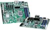
Overview Intel®Server Board S1200BT TPS 2. Overview The Intel® Server Board S1200BT is a monolithic printed circuit board (PCB) with features designed to support entry-level severs. It has two board SKUs, namely S1200BTL and S1200BTS. 2.1 Intel® Server Board S1200BT Feature Set Feature Processor - Intel S1200BTL | Product Specification - Page 15
Intel®Server Board S1200BT TPS Overview Feature Add-in PCI Card, PCI Express* Card System Fan Support Video Onboard Hard Drive RAID Support LAN Server Management Security Description of S1200BTL Slot1: One 5V PCI 32 bit/33 MHz connector Slot3: One PCI Express* Gen2 x8 (x4 throughput) - Intel S1200BTL | Product Specification - Page 16
Overview 2.2 Server Board Layout Intel®Server Board S1200BT TPS Figure 1. Intel® Server Board S1200BTL Picture 4 Revision 1.0 Intel order number G13326-003 - Intel S1200BTL | Product Specification - Page 17
Intel®Server Board S1200BT TPS Overview Figure 2. Intel® Server Board S1200BTS Picture 2.2.1 Server Board Connector and Component Layout The following figure shows the board layout of the server board. Each connector and major component is identified by a number or letter, and Table 2 provides - Intel S1200BTL | Product Specification - Page 18
Overview Intel®Server Board S1200BT TPS Figure 3. Intel® Server Board S1200BTL Layout Table 2. Major Board Components Description Description A Slot 1, 32 Mbit/33 MHz PCI R System FAN2 and System FAN3 Connector B TPM S CPU connector C Slot 3/4, PCI Express* Gen2 x4 (x8 connector) T - Intel S1200BTL | Product Specification - Page 19
USB Connector EE CMOS battery FF Four 3Gb/s SATA ports GG Two 6Gb/s SATA ports HH Smart module Overview Figure 4. Intel® Server Board S1200BTS Layout Table 3. Major Board Components Description A Slot 4, 32 Mbit/33 MHz PCI N SYS FAN 1 B Slot 5. PCI Express* Gen2 x8 (x8 connector); Slot 6, PCI - Intel S1200BTL | Product Specification - Page 20
Overview Intel®Server Board S1200BT TPS Description C SATA_KEY D Slot 7, PCI Express* Gen2 x8 (x16 connector) E U Low profile USB connector V Internal USB W CMOS battery X Front Panel Y HDD LED 2.2.2 Intel® Server Board S1200BTL Mechanical Drawings 8 Revision 1.0 Intel order number G13326-003 - Intel S1200BTL | Product Specification - Page 21
Intel®Server Board S1200BT TPS Overview Figure 5. Intel® Server Board S1200BTL - Hole and Component Positions Revision 1.0 9 Intel order number G13326-003 - Intel S1200BTL | Product Specification - Page 22
Overview Intel®Server Board S1200BT TPS Figure 6. Intel® Server Board S1200BTL - Major Connector Pin Location (1 of 2) 10 Revision 1.0 Intel order number G13326-003 - Intel S1200BTL | Product Specification - Page 23
Intel®Server Board S1200BT TPS Overview Figure 7. Intel® Server Board S1200BTL - Major Connector Pin Location (2 of 2) Revision 1.0 11 Intel order number G13326-003 - Intel S1200BTL | Product Specification - Page 24
Overview Intel®Server Board S1200BT TPS Figure 8. Intel® Server Board S1200BTL - Primary Side Keepout Zone 12 Revision 1.0 Intel order number G13326-003 - Intel S1200BTL | Product Specification - Page 25
Intel®Server Board S1200BT TPS Overview Figure 9. Intel® Server Board S1200BTL - Secondary Side Keepout Zone Revision 1.0 13 Intel order number G13326-003 - Intel S1200BTL | Product Specification - Page 26
figure shows the layout of the rear I/O components for the server board. A Serial Port A B Video C NIC Port 1 (1 Gb) and Dual USB Port Connector D NIC port 2 (1 Gb) and Dual USB Port Connector Figure 10. Intel® Server Board S1200BT Rear I/O Layout 14 Revision 1.0 Intel order number G13326-003 - Intel S1200BTL | Product Specification - Page 27
Chipset. The chipset is designed for systems based on the Intel® Xeon® processor in the FCLGA 1155 socket package. The Intel® Server Board S1200BTL uses Intel® C204 Chipset and the Intel® Server Board S1200BTS uses Intel® C202 Chipset. The Intel® Xeon® Processor E3-1200 Series are made up of multi - Intel S1200BTL | Product Specification - Page 28
I/O USB Ports x2 Figure 12. Intel® Server Board S1200BTS Functional Block Diagram 3.1 Processor Sub-System The Intel® Server Board S1200BT supports the following processor: Intel® Xeon® Processor E3-1200 Series. Intel® Core™ Processor i3-2100 Series The Intel® Xeon® Processor E3-1200 Series - Intel S1200BTL | Product Specification - Page 29
Intel®Server Board S1200BT TPS Functional Architecture The server board does not support previous generations of the Intel® Xeon® processors. The list of supported processors may be found at http://serverconfigurator.intel.com. Note: The workstation processor is not supported in BIOS Setup. - Intel S1200BTL | Product Specification - Page 30
Memory Supported The Intel® Server Board S1200BT family supports various DDR3 DIMM modules of different types and sizes and speeds. In this section, the statements of support are subject to qualification in two ways: For S1200 Server Boards with an SNB-DT processor, the Server Board and the BIOS - Intel S1200BTL | Product Specification - Page 31
POST Diagnostic LED code 0xED. Note: Mixed DIMM configurations are not supported and not validated by Intel®. 3.2.3 Memory Map and Population Rules The overall configuration is a single processor with two channels, and two DIMM slots on each channel on the Intel® Server Board S1200BT. All memory - Intel S1200BTL | Product Specification - Page 32
Functional Architecture Intel®Server Board S1200BT TPS The maximum memory bandwidth is 10.6 GB/s in Single- A1 Dual Channel Symmetric Dual Channel Symmetric 3 DIMMs A1 Intel®Flex Memory Dual Channel Symmetric 3 DIMMs A1 Intel®Flex Memory Dual Channel Symmetric 4 DIMMs A1 Dual Channel - Intel S1200BTL | Product Specification - Page 33
interleaving. 3.2.5 Memory RAS Support For Intel® Server Board S1200BT, the form of Memory RAS provided is Error Correction Code (ECC). ECC uses specific step in memory initialization in which all of memory is cleared to zeroes before the ECC function is enabled, in order to bring the ECC codes - Intel S1200BTL | Product Specification - Page 34
Functional Architecture Intel®Server Board S1200BT TPS USB host interface SMBus Host interface Serial Peripheral interface LAN interface ACPI interface 3.4 I/O Sub-system Intel® C200 Series PCH provides extensive I/O support. 3.4.1 Digital Media Interface (DMI) Direct Media - Intel S1200BTL | Product Specification - Page 35
USB 2.0 ports. One port on internal smart module connector (J1J2) on Intel® Server Board S1200BTL. 3.4.5.1 Native USB Support During the power-on self test (POST), the BIOS initializes and configures the USB subsystem. The BIOS is capable of initializing and using the following types of USB - Intel S1200BTL | Product Specification - Page 36
Intel®Server Board S1200BT TPS USB Specification-compliant keyboards. USB Specification-compliant mouse. USB Specification-compliant storage devices that utilize bulk-only transport mechanism. USB devices are scanned to determine if they are required for booting. The BIOS supports - Intel S1200BTL | Product Specification - Page 37
Intel®Server Board S1200BT TPS Functional Architecture JTAG Master Eight I2C interfaces with master-slave and SMBus timeout support. All interfaces are SMBus 2.0 DMA support LED support with programmable blink rate controls on GPIOs Port 80h snooping capability Secondary Service - Intel S1200BTL | Product Specification - Page 38
Functional Architecture Intel®Server Board S1200BT TPS Figure 13. Integrated BMC Hardware 3.6.1 Integrated BMC is a dedicated management NIC that is not shared with the host. For these channels, support can be enabled for IPMI-over-LAN and DHCP. For security reasons, embedded LAN channels - Intel S1200BTL | Product Specification - Page 39
S1200BTS) Pin-out Pin 1 2 3 4 5 6 7 8 9 Signal Name DCD DSR RX RTS TX CTS DTR RI GND Serial Port B Header Pin-out 3.6.4 Floppy Disk Controller The server board does not support a floppy disk controller interface. However, the system BIOS recognizes USB floppy devices. Revision 1.0 27 Intel - Intel S1200BTL | Product Specification - Page 40
Functional Architecture Intel®Server Board S1200BT TPS 3.6.5 Keyboard and Mouse Support The server board does not support PS/2 interface keyboards and mouse. However, the system BIOS recognizes USB specification-compliant keyboard and mouse. 3.6.6 Wake-up Control The super I/O contains - Intel S1200BTL | Product Specification - Page 41
supported. 3.8 Network Interface Controller (NIC) The Intel® Server Board S1200BT supports two network interfaces, One is provided from the onboard Intel small area so it can be used for server and client configurations as a LAN on Motherboard (LOM) design. External interfaces provided on the - Intel S1200BTL | Product Specification - Page 42
Functional Architecture Intel®Server Board S1200BT TPS provides a standard IEEE 802.3 Ethernet interface for 1000BASE-T, 100BASE-TX, and 10BASE-T applications (802.3, 802.3u, and 802.3ab). Lewisville also supports the Energy Efficient Ethernet (EEE) 802.az specification. The 82579 operates with - Intel S1200BTL | Product Specification - Page 43
Intel®Server Board S1200BT TPS Functional Architecture 3.11 TPM (Trusted Platform Module) There is one TPM module connector. The detail information is listed below: Embedded TPM 1.2 firmware 33-MHz Low Pin Count (LPC) interface V1.1 Compliant with TCG PC client specific TPM Implementation - Intel S1200BTL | Product Specification - Page 44
S1200BT TPS 4. Platform Management This chapter is only for The Intel® Server Board S1200BTL. The platform management subsystem is based on the Integrated BMC features of the ServerEngines* Pilot III. The onboard platform management subsystem consists of communication buses, sensors, system BIOS - Intel S1200BTL | Product Specification - Page 45
Intel®Server Board S1200BT TPS Platform Management 4.1 Feature Support 4.1.1 IPMI 2.0 Features Baseboard management controller (BMC). IPMI Watchdog timer Messaging support, including command bridging and user/session support Chassis device functionality, including power/reset control - Intel S1200BTL | Product Specification - Page 46
Platform Management Intel®Server Board S1200BT TPS Signal testing support: The BMC provides test commands for setting and getting platform signal states. The BMC generates diagnostic beep codes for fault conditions. System GUID storage and retrieval Front panel management: The BMC controls - Intel S1200BTL | Product Specification - Page 47
BMC Firmware Update FRB 2 Chassis Intrusion Detection Fan Redundancy Monitoring Hot-Swap Fan Support Acoustic Management Diagnostic Beep Code Support Power State Retention ARP/DHCP Support PECI Thermal Management Support E-mail Alerting Embedded Web Server SSH Support Integrated KVM Integrated - Intel S1200BTL | Product Specification - Page 48
Intel®Server Board S1200BT TPS 4.2.1 Enabling Advanced Management Features The Advanced management features are to be delivered as part of the Integrated BMC firmware image. The Integrated BMC's baseboard SPI flash contains code . If the browser has no Java support, such as with a small handheld - Intel S1200BTL | Product Specification - Page 49
Intel®Server Board S1200BT TPS Platform Management The Remote Console window is a Java Applet that establishes TCP connections to the Integrated BMC. The protocol that is run over these - Intel S1200BTL | Product Specification - Page 50
Platform Management Intel®Server Board S1200BT TPS 4.2.3 Media Redirection The embedded web server provides a Java applet to enable remote operating systems), copy files, update BIOS, and so on, or boot the server from this device. The following capabilities are supported: The operation of - Intel S1200BTL | Product Specification - Page 51
Intel®Server Board S1200BT TPS Platform Management 4.2.3.1 Availability The default inactivity initiated. Encryption using 128-bit SSL is supported. User authentication is based on user id and password. The GUI presented by the embedded web server authenticates the user before allowing a web - Intel S1200BTL | Product Specification - Page 52
Intel®Server Board S1200BT GUI unless the system has been updated to support these advanced features. A partial list of additional features supported by the web GUI includes: board, and chassis. Display of BMC-owned sensors (name, status, current reading, enabled thresholds), including color-code - Intel S1200BTL | Product Specification - Page 53
Intel®Server Board S1200BT TPS Platform repository. This does not include any ―event-only‖ sensors. (All BIOS sensors and some Integrated BMC and ME sensors are ―event-only‖; a set of DCMI-specific IPMI OEM commands. BTP1200-LC platform will support DCMI 1.0 specification. 4.2.7 Local Directory - Intel S1200BTL | Product Specification - Page 54
Static-OLTT): OLTT control registers are configured by BIOS MRC remain fixed after post. The system Update Utility (FRUSDR utility) is a program used to write platform-specific configuration data to NVRAM on the server board. It allows the user to select which supported chassis (Intel® or Non-Intel - Intel S1200BTL | Product Specification - Page 55
Intel®Server Board S1200BT TPS Platform Management The NM feature is implemented by a complementary architecture utilizing the ME, Integrated BMC, BIOS, and an algorithms defined in the NPTM specification. 4.4.2 Features NM provides feature support for policy management, monitoring and - Intel S1200BTL | Product Specification - Page 56
Intel®Server Board S1200BT to forward commands to ME and send response back to originator. Similarly events generated by ME to the Integrated BMC ( packet, following standard IPMI bridging as described in the IPMI 2.0 Specification. Integrated BMC forwards the encapsulated command it to NM engine on - Intel S1200BTL | Product Specification - Page 57
Intel®Server Board S1200BT TPS Platform Management Alerts that signify fault conditions that should ‖ OEM command. 4.4.3.2 BIOS-Integreated BMC-ME Communication In this generation of platforms, the BIOS communicates directly with the ME via HECI. Revision 1.0 45 Intel order number G13326-003 - Intel S1200BTL | Product Specification - Page 58
Management Capability for Intel®Server Board S1200BTS Intel®Server Board S1200BT TPS 5. Server Management Capability for Intel® Server Board S1200BTS 5.1 Supper I/O 5.1.1 Key Features of supper I/O The W83627DHG-P is from the Nuvoton's Super I/O product line. This family features the LPC - Intel S1200BTL | Product Specification - Page 59
for to identify board family. -―S1200BT‖ is used to identify BIOS builds for S1200BT server boards. OEMID = Three-character OEM BIOS Identifier, to identify the board BIOS ―owner‖. Changed only if and when BIOS Development management authorizes a BIOS program for a specific OEM customer. -―86B - Intel S1200BTL | Product Specification - Page 60
User Interface Intel®Server Board S1200BT TPS RelNum = Release Number, four decimal digits which are changed to identify distinct BIOS Releases. BIOS Releases are major collections of fixes and changes in functionality. -―0001‖ is the starting Release Number for all platform BIOS releases, for - Intel S1200BTL | Product Specification - Page 61
Intel®Server Board S1200BT TPS BIOS User Interface Table 13. POST HotKeys Recognized HotKey Combination Function Enter Setup Pop up BIOS Boot Menu Network boot 6.3 POST Logo Screen/Diagnostic Screen The Logo Screen/Diagnostic Screen appears in one of two forms: If Quiet Boot - Intel S1200BTL | Product Specification - Page 62
User Interface Intel®Server Board S1200BT TPS 6.4 BIOS Boot Pop-up Menu The BIOS Boot Specification (BBS) provides a Boot Pop-up boot order in the BIOS setup. The pop-up menu simply lists all of the available devices from which the system can be booted, and allows a manual selection of the desired - Intel S1200BTL | Product Specification - Page 63
Intel®Server Board S1200BT TPS BIOS User Interface Note: If an Administrative Password has Setup Page Layout The Setup page layout is sectioned into functional areas. Each occupies a specific area of the screen and has dedicated functionality. The following table lists and describes each - Intel S1200BTL | Product Specification - Page 64
BIOS User Interface Intel®Server Board S1200BT TPS Each Setup menu page contains a number of features. Each displaying the full list. On 106-key Japanese keyboards, the plus key has a different scan code than the plus key on the other keyboards, but will have the same effect. Pressing the - Intel S1200BTL | Product Specification - Page 65
Intel®Server Board S1200BT TPS BIOS User Interface Key Option Save and Exit Description Pressing the key causes the following message to display: Save configuration and reset? Yes No - Intel S1200BTL | Product Specification - Page 66
BIOS User Interface Intel®Server Board S1200BT TPS Information enclosed in square brackets ([ ]) in the tables identifies areas where the PCI Configuration System Acoustic and Performance Configuration 3rd Level Screens - - - - - - - - - 54 Revision 1.0 Intel order number G13326-003 - Intel S1200BTL | Product Specification - Page 67
Intel®Server Board S1200BT TPS Categories (Top Tabs) Security Screen (Tab) Server Management Screen (Tab With BMC Only] [Non-BMC Event Log Screen (Tab) - [Non-BMC Only] Exit Screen (Tab) - BIOS User Interface 3rd Level Screens - - - - - - Realtime Temperature and Voltage Status - Revision 1.0 - Intel S1200BTL | Product Specification - Page 68
Intel®Server Board S1200BT TPS 6.5.2.2 Main Screen (Tab) The Main Screen is the first screen that appears when the BIOS Setup configuration utility is entered, unless an error has occurred. If an error has occurred, the Error Manager Screen appears instead. Main Advanced Security Server - Intel S1200BTL | Product Specification - Page 69
Intel®Server Board S1200BT TPS BIOS User Interface Screen Field Descriptions: 1. Logged in as: Option Values: None> Comments: Information only. Displays the total physical memory installed in the system, in MB or GB. The term physical memory indicates the total memory discovered in the form of - Intel S1200BTL | Product Specification - Page 70
BIOS User Interface Intel®Server Board S1200BT TPS [Enabled] - Display the logo screen during POST. [Disabled] - Display the diagnostic screen during POST. 7. POST Error Pause at the top of the Setup screen until the Advanced screen is selected. 58 Revision 1.0 Intel order number G13326-003 - Intel S1200BTL | Product Specification - Page 71
Intel®Server Board S1200BT TPS BIOS User Interface Main Advanced Security Server Management Boot Options Boot Manager ► Processor Configuration ► Memory Configuration ► Mass Storage Controller Configuration ► Serial Port Configuration ► USB Configuration ► PCI Configuration ► System Acoustic and - Intel S1200BTL | Product Specification - Page 72
BIOS User Interface Intel®Server Board S1200BT TPS Screen Field Descriptions: 1. Processor Configuration Option Values: Help Text: View/Configure processor Option Values: Help Text: View/Configure PCI information and settings. 60 Revision 1.0 Intel order number G13326-003 - Intel S1200BTL | Product Specification - Page 73
Intel®Server Board S1200BT TPS BIOS User Interface Comments: Selection only. Position to this line and press the displays the processor identification and microcode level, core frequency, cache sizes, Intel® QuickPath Interconnect information for all processors currently installed. It also allows - Intel S1200BTL | Product Specification - Page 74
® Hyper-Threading Tech Core Multi-Processing Execute Disable Bit Intel® Virtualization Technology Intel® VT for Directed I/O Interrupt Remapping Pass-through DMA Support Hardware Prefetcher Adjacent Cache Line Prefetch Intel®Server Board S1200BT TPS - Intel S1200BTL | Product Specification - Page 75
Intel®Server Board S1200BT TPS BIOS User Interface Screen Field Descriptions: 1. Processor ID Option Values: Help Text: Comments: Information only. Displays the Processor Signature value (from the CPUID instruction Information only. Displays size in MB of the processor L3 Cache - Intel S1200BTL | Product Specification - Page 76
BIOS User Interface Intel®Server Board S1200BT TPS Option Values: Help Text: Comments: Information only. Displays Brand ID string read from processor with CPUID instruction. 7. Intel® Turbo Boost Technology Option Values: Enabled Disabled Help Text: Intel® - Intel S1200BTL | Product Specification - Page 77
Intel®Server Board S1200BT TPS BIOS User Interface Help Text: Enable/Disable Processor C3 ( of this feature. Comments: This option is only visible if all processors installed in the system support Intel® Hyper-Threading Technology. 13. Core Multi-Processing Option Values: All 2 4 Help Text: - Intel S1200BTL | Product Specification - Page 78
BIOS User Interface Intel®Server Board S1200BT TPS 15. Intel® Virtualization Technology Option Values: Enabled Disabled Help Text: Intel® Virtualization Technology allows a platform to run multiple operating systems and applications in independent partitions. Note: A change to this option - Intel S1200BTL | Product Specification - Page 79
Intel®Server Board S1200BT TPS BIOS User Interface Comments: This option is only visible if all processors installed in the system support Intel® VT. The software configuration installed on the system must support this feature in order for it to be enabled. 16. Intel® VT for Directed I/O Option - Intel S1200BTL | Product Specification - Page 80
BIOS User Interface Intel®Server Board S1200BT TPS Note: Modifying this setting may affect system performance. Comments: Installed in System> Single Channel/Dual Channel Symmetric/Intel® Flex 1066/1333 Auto/1066/1333 Installed/Not Installed/Failed/Disabled Installed/ - Intel S1200BTL | Product Specification - Page 81
Intel®Server Board S1200BT TPS BIOS User Interface Screen Field Descriptions: 1. Total Memory Option Values Memory Option Values: Help Text: Comments: OS in MB or GB. Information only. Displays the amount of memory available to the The Effective Memory - Intel S1200BTL | Product Specification - Page 82
BIOS User Interface Intel®Server Board S1200BT TPS 3. Current Configuration Option Values: Single Channel Dual Channel Symmetric Intel® Flex Help Text: : Force specific Memory Operating Speed or use Auto setting. Comments: Displays the state of each DIMM socket present on the board. Each - Intel S1200BTL | Product Specification - Page 83
Intel®Server Board S1200BT TPS BIOS User Interface Comments: Information only, for S1200 boards: Displays the state of each DIMM socket present on the board. Each DIMM socket field reflects one of the following possible states: Installed - There is a DDR3 DIMM installed in this slot. Not - Intel S1200BTL | Product Specification - Page 84
BIOS User Interface Advanced Serial Port Configuration Serial A Enable Address IRQ Serial B Enable Address IRQ Intel®Server Board S1200BT TPS Enabled/Disabled 3F8h/2F8h/3E8h/2E8h 3 or 4 Enabled/Disabled 3F8h/2F8h/3E8h/2E8h 3 or 4 Figure 20. Serial Port Configuration Screen 6.5.2.8 USB - Intel S1200BTL | Product Specification - Page 85
Intel®Server Board S1200BT TPS BIOS User Interface Advanced USB Configuration Detected USB Devices USB Controller Legacy USB Support Port 60/64 Emulation Make USB Devices Non-Bootable Enabled/Disabled Enabled/Disabled/Auto Enabled/Disabled Enabled/Disabled USB - Intel S1200BTL | Product Specification - Page 86
BIOS User Interface Advanced PCI Configuration Maximize Memory below 4GB Memory Mapped I/O Enabled / Disabled Enabled / Disabled Intel®Server Board S1200BT TPS Figure 22. PCI Configuration Screen 10. Wake on LAN (PME) Option Values: Enabled Disabled - Intel S1200BTL | Product Specification - Page 87
Intel®Server Board S1200BT TPS BIOS User Interface To access this screen from the Main screen, the user to enable and activate the Trusted Platform Module (TPM) security settings on those boards that support TPM. To access this screen from the Main screen or other top-level Tab screen, press - Intel S1200BTL | Product Specification - Page 88
BIOS User Interface Intel®Server Board S1200BT TPS 6.5.2.12 Server Management Screen (Tab) The Server Management screen allows the user to configure several server management features. This screen also provides an access point to the screens for configuring console redirection, displaying system - Intel S1200BTL | Product Specification - Page 89
Intel®Server Board S1200BT TPS BIOS User Interface Main Advanced Security Server Management Boot Options Boot Manager minutes / 10 minutes / 15 minutes / 20 minutes Figure 26. Server Management Screen (S1200BTS) 6.5.2.13 Console Redirection The Console Redirection screen allows the user to - Intel S1200BTL | Product Specification - Page 90
BIOS User Interface Intel®Server Board S1200BT TPS 6.5.2.14 System Information The System Information screen allows the user to view part numbers, serial numbers, and firmware revisions. To access this screen from the Main screen, select Server Management > System Information. To move to - Intel S1200BTL | Product Specification - Page 91
Intel®Server Board S1200BT TPS System Information Board Part Number Board Serial Number System Part Number System Serial Number Chassis Part Number Chassis Serial Number Asset Tag HSC Firmware Revision ME Firmware Revision UUID Server Management - Intel S1200BTL | Product Specification - Page 92
BIOS User Interface Intel®Server Board S1200BT TPS BMC LAN Configuration Server Management Baseboard LAN configuration IP Source IP Address Subnet Mask Gateway IP Intel® RMM4 LAN configuration Intel® RMM4 IP Source IP Address Subnet Mask Gateway IP[ Static/Dynamic [0.0.0.0 IP display/edit] - Intel S1200BTL | Product Specification - Page 93
Intel®Server Board S1200BT TPS Hardware Monitor Server Management ► Real-time Temperature and Voltage Status Fan Controller Auto / Manual CPU Fan Altitude System Fan Altitude 300m/900m/1500m/3000m 300m/900m/1500m/3000m BIOS User Interface Figure 31. Hardware Monitor Screen, Auto Fan Control - Intel S1200BTL | Product Specification - Page 94
BIOS User Interface Intel®Server Board S1200BT TPS To access this screen from the Main screen, select Server Management > Hardware Monitor > Realtime Temperature and Voltage Status. To move to another screen, press the key to return to the Hardware Monitor screen, if - Intel S1200BTL | Product Specification - Page 95
Intel®Server Board S1200BT TPS BIOS User Interface Main Advanced Security Server Management Boot Options Boot Manager System Boot Timeout Boot The Hard Disk Order screen allows the user to control the order in which BIOS attempts to boot from the hard disk drives installed in the system. This - Intel S1200BTL | Product Specification - Page 96
Disk Order Hard Disk #1 Hard Disk #2 Intel®Server Board S1200BT TPS Boot Options Figure 35. Hard Disk Order Screen 6.5.2.20 CDROM Order The CDROM Order screen allows the user to control the order in which BIOS attempts to boot from the - Intel S1200BTL | Product Specification - Page 97
Intel®Server Board S1200BT TPS Floppy Order Floppy Disk #1 Floppy Disk #2 BIOS User Interface Boot Options Figure 37. Floppy Order Screen 6.5.2.22 Network Device Order The Network Device Order - Intel S1200BTL | Product Specification - Page 98
BIOS User Interface BEV Device Order BEV Device #1 BEV Device #2 Intel®Server Board S1200BT TPS Boot Options Figure 39. BEV Device to return to the Boot Options screen, then select the desired screen. 86 Revision 1.0 Intel order number G13326-003 - Intel S1200BTL | Product Specification - Page 99
Intel®Server Board S1200BT TPS Delete EFI Boot Option Delete Boot Option BIOS User Interface Boot Options Select one The Error Manager screen displays any POST Error Codes encountered during BIOS POST, along with an explanation of the meaning of the code. To access this screen from the Main screen - Intel S1200BTL | Product Specification - Page 100
BIOS User Interface Error Manager ERROR CODE Exit SEVERITY INSTANCE Intel®Server Board S1200BT TPS Figure 43. Error Manager Screen 6.5.2.28 System Event Log Screen (Tab) The System Event Log screen appears only for server boards (other than Compute Module boards) which do not have an onboard - Intel S1200BTL | Product Specification - Page 101
Intel®Server Board S1200BT TPS BIOS User Interface 6.5.2.29 Exit Screen (Tab) The Exit screen allows the user to choose whether to save or discard the configuration changes made on other Setup screens. It also allows the user to restore the BIOS settings to the factory defaults or to save or - Intel S1200BTL | Product Specification - Page 102
Connector/Header Locations and Pin-outs Intel®Server Board S1200BT TPS 7. Connector/Header Locations and Pin-outs 7.1 Board Connector Information The following section provides detailed information regarding all connectors, headers, and jumpers on the server board. It lists all connector types - Intel S1200BTL | Product Specification - Page 103
Intel®Server Board S1200BT TPS Connector/Header Locations and Pin-outs Table 18. Board Connector Matrix on S1200BTS Connector Quantity Reference Designators Connector Type Pin Count Power supply 2 CPU 1 Main memory 4 CPU Fan 1 System Fans 3 Battery 1 NIC/Stack 2x USB 2 Video 1 - Intel S1200BTL | Product Specification - Page 104
on the server board to support the optional Intel® Remote Management Module 4 lite. This server board does not support third-party management cards. Note: This connector is not compatible with the Intel® Remote Management Module (Intel® RMM), the Intel® Remote Management Module 2 (Intel® RMM2) or - Intel S1200BTL | Product Specification - Page 105
The server board provides a 24-pin SSI front panel connector (J1C1) for use with Intel® and third-party chassis. The following table provides the pin-out for this connector. Table 26. Front Panel SSI Standard 24-pin Connector Pin-out (J1C1 on S1200BTL or J1C2 on S1200BTS) Revision 1.0 93 Intel - Intel S1200BTL | Product Specification - Page 106
outs Intel®Server Board S1200BT board connector at location J1C1 as is implemented in Intel® Server Systems configured using a bridge board and a hot- swap backplane. 7.4.1 Power Button The BIOS supports a safety mechanism, if the BIOS fails to service the request, the Integrated BMC - Intel S1200BTL | Product Specification - Page 107
Intel®Server Board S1200BT TPS Connector/Header Locations and Pin-outs 7.4.2 Reset Button The platform supports a front control panel reset button. Pressing the reset button initiates a request forwarded by the Integrated BMC to the chipset. The BIOS does not affect the behavior of the reset - Intel S1200BTL | Product Specification - Page 108
Connector/Header Locations and Pin-outs Intel®Server Board S1200BT TPS 7.5 I/O Connectors 7.5.1 VGA Connector The following table details the pin-out definition of the VGA connector (J7A1 on S1200BTL and J6A1 on S1200BTS): Table 28. VGA Connector Pin-out Pin Signal Name 1 V_IO_R_CONN 2 - Intel S1200BTL | Product Specification - Page 109
Intel®Server Board S1200BT TPS Connector/Header Locations and Pin-outs Table 30. RJ-45 10/100/1000 NIC pair Positive side of receive differential pair Ground 7.5.4 SAS Connectors The Intel® Server Board S1200BTL provides one SAS connector. The pin configuration is identical and defined - Intel S1200BTL | Product Specification - Page 110
Connector/Header Locations and Pin-outs Intel®Server Board S1200BT TPS Table 33. SAS Connector Pin-out (J2H1) Pin Signal Name 1 pair Positive side of receive differential pair Ground 7.5.5 Serial Port Connectors The server board provides one external DB9 Serial A port (J8A1) and one internal - Intel S1200BTL | Product Specification - Page 111
Intel®Server Board S1200BT TPS Connector/Header Locations and Pin-outs 7.5.6 USB Connector There are four external USB ports on two NIC/USB combinations. Section 5.5.2 details the pinout of the connector. Two 2x5 connector on the server board (J1D1, J1E1) provides an option to support an - Intel S1200BTL | Product Specification - Page 112
Connector/Header Locations and Pin-outs Intel®Server Board S1200BT TPS 7.6 PCI Express* Slot/PCI Slot/Riser Card Slot A PCI-E Riser card will GND GND P2E_CPU_S6_RXP P2E_CPU_S6_RXN GND NC NC GND P2E_CPU_S6_RXN P2E_CPU_S6_RXP GND GND 100 Revision 1.0 Intel order number G13326-003 - Intel S1200BTL | Product Specification - Page 113
Intel®Server Board S1200BT TPS Connector/Header Locations and Pin-outs Pin Signal B39 GND B40 GND B41 PETP6 B42 PETN6 B43 GND B44 GND B45 PETP7 B46 PETN7 NC NC GND GND NC NC GND GND NC NC GND GND NC NC GND GND NC NC GND GND NC NC GND Revision 1.0 101 Intel order number G13326-003 - Intel S1200BTL | Product Specification - Page 114
Connector/Header Locations and Pin-outs Intel®Server Board S1200BT TPS Table 39. Three PCI Express* x8 connectors (J2B2, J3B1 and J4B2) Pin A1 A2 A3 A4 A5 A6 # Ground TRDY# Ground STOP# +3.3V RSVD RSVD Ground PAR AD[15] +3.3V AD[13] AD[11] Ground 102 Revision 1.0 Intel order number G13326-003 - Intel S1200BTL | Product Specification - Page 115
Intel®Server Board S1200BT TPS Connector/Header Locations and Pin-outs Pin # B18 B19 B20 3V AD[06] AD[04] Ground AD[02] AD[00] V_IO REQ64# +5V +5V 7.7 Fan Headers The server board provides five SSI-compliant 4-pin fan headers to be used as the CPU and chassis. The pin configuration for each of - Intel S1200BTL | Product Specification - Page 116
Blocks Intel®Server Board S1200BT TPS 8. Jumper Blocks The server board has several 3-pin jumper blocks that can be used to configure, protect or recover specific features of the server board. Figure 46. Jumper Blocks (J4A2, J1F1, J1F3, J1F2, and J1E2) on S1200BTL Table 42. Server Board Jumpers - Intel S1200BTL | Product Specification - Page 117
Intel®Server Board S1200BT TPS Jumper Blocks Figure 47. Jumper Blocks (J2G1, J1G1, J1H3, and J2J1) on S1200BTS Table 43. Server Board Jumpers (J2G1, J1G1, J1H3, and J2J1) on S1200BTS Jumper Name Pins J1H3: CMOS 1-2 Clear 2-3 J1J2: ME Force 1-2 Update with the recovery BIOS image. 8.1 CMOS - Intel S1200BTL | Product Specification - Page 118
Jumper Blocks Intel®Server Board S1200BT TPS features has changed from previous generation Intel® server boards. The following procedure outlines the new usage model. 8.1.1 Clearing the CMOS To clear the CMOS, perform the following steps: 1. Power down the server. Do not unplug the power cord. - Intel S1200BTL | Product Specification - Page 119
Intel®Server Board S1200BT TPS Jumper Blocks 8.2 Integrated BMC Force Update Procedure (Only for The Intel® Server Board S1200BTL) When performing the standard Integrated BMC firmware update procedure, the update utility places the Integrated BMC into an update mode, allowing the firmware to load - Intel S1200BTL | Product Specification - Page 120
Jumper Blocks Intel®Server Board S1200BT TPS 1. Power down and remove the AC power cord. 2. Open the server chassis. For instructions, see your server chassis documentation. 3. Move jumper from the default operating position (covering pins 1 and 2) to the enabled position (covering pins 2 and 3). - Intel S1200BTL | Product Specification - Page 121
Intel®Server Board S1200BT TPS Intel®Light Guided Diagnostics 9. Intel® Light Guided Diagnostics The server board has several on-board diagnostic LEDs to assist in troubleshooting board-level issues. This section shows where each LED is located on the server board and describes the function of - Intel S1200BTL | Product Specification - Page 122
Intel®Light Guided Diagnostics Intel®Server Board S1200BT TPS Figure 48. POST Code Diagnostic LED Location A Status LED B ID LED C Diagnostic LED #7 (MSB LED) D Diagnostic LED #6 E Diagnostic LED #5 F Diagnostic LED #4 G Diagnostic LED #3 H Diagnostic LED #2 I Diagnostic LED #1 J Diagnostic LED - Intel S1200BTL | Product Specification - Page 123
Server Board Design Specifications intel.com/support/motherboards/server to get the updated MTBF report for Intel® Server Board S1200BT family. 10.2.1 Processor Power Support The server board supports the Thermal Design Power (TDP) guideline for Intel® Xeon® processor. The Flexible Motherboard - Intel S1200BTL | Product Specification - Page 124
and Environmental Specifications Intel®Server Board S1200BT TPS suggested thermal and current design values for anticipating future processor needs. The following table provides maximum values for Icc, TDP power and TCASE for the Intel® Xeon® SandyBridge Series processor. Table 46. Intel® Xeon - Intel S1200BTL | Product Specification - Page 125
Intel®Server Board S1200BT TPS Design and Environmental Specifications 10.3.1 Grounding The grounds kHz at duty cycles ranging from 10%-90%. The load transient repetition rate is only a test specification. The step load may occur anywhere within the Min load to the Max load conditions. Output - Intel S1200BTL | Product Specification - Page 126
Design and Environmental Specifications Intel®Server Board S1200BT TPS Output +5 VSB ∆ Step Load Size (See note 2) 0.5 A Load Slew Rate 0.25 A/µsec 10 Timing Requirements The timing requirements for the power supply operation are as follows: 114 Revision 1.0 Intel order number G13326-003 - Intel S1200BTL | Product Specification - Page 127
Intel®Server Board S1200BT TPS Design and Environmental Specifications The output voltages must rise from 10% to within regulation limits (Tvout_rise) within 5 ms to 70 ms 1.0 ms to 25.0 ms. Units Msec Msec Msec Figure 49. Output Voltage Timing Revision 1.0 115 Intel order number G13326-003 - Intel S1200BTL | Product Specification - Page 128
Design and Environmental Specifications Intel®Server Board S1200BT TPS Table 53. Turn On/Off Timing Item Tsb_on_delay Tac_on_delay Tvout_holdup Tpwok_holdup Tpson_on_delay Tpson_pwok Tpwok_on Tpwok_off Tpwok_low Tsb_vout T5VSB_holdup Description Delay from AC being applied - Intel S1200BTL | Product Specification - Page 129
Intel®Server Board S1200BT TPS Design and Environmental Specifications 10.3.11 Residual Voltage Immunity in Standby Mode The power supply is immune (OVP) Limits Output Voltage +3.3 V +5 V +12 V Minimum (V) 3.9 5.7 13.3 Maximum (V) 4.5 6.2 14.5 Revision 1.0 117 Intel order number G13326-003 - Intel S1200BTL | Product Specification - Page 130
Design and Environmental Specifications Output Voltage -12 V +5 VSB Intel®Server Board S1200BT TPS Minimum (V) -13.3 5.7 Maximum (V) -14.5 6.5 118 Revision 1.0 Intel order number G13326-003 - Intel S1200BTL | Product Specification - Page 131
be removed. With AC power plugged into the server board, 5-Volt standby is still present even though the server board is powered off. When updating BIOS and BMC, AC power must be on. Supports only Intel® Xeon® Processor E3-1200 Series with 95 W or Intel® Core™ Processor i3-2100 and less Thermal - Intel S1200BTL | Product Specification - Page 132
Tables Intel®Server Board S1200BT TPS Appendix B: Integrated BMC Sensor Tables Intel® Server Board S1200BTL implements the below sensors: Sensor Type Codes Sensor table given below lists the sensor identification numbers and information regarding the sensor type, name, supported thresholds - Intel S1200BTL | Product Specification - Page 133
Intel®Server Board S1200BT TPS Appendix B: Integrated BMC Sensor Tables T: Threshold value Rearm Sensors The rearm is a request for the event status for a sensor to be rechecked and updated upon a transition between good and bad states. Rearming the sensors can be done manually or automatically. - Intel S1200BTL | Product Specification - Page 134
B: Integrated BMC Sensor Tables Intel®Server Board S1200BT TPS Full Sensor Name (Sensor name in SDR) Power Unit Status (Pwr Unit Status) Sensor # Platform Applicability 01h All Sensor Type Power Unit 09h Table 56. BMC Core Sensors Event/Reading Type Sensor Specific 6Fh Event Offset Triggers - Intel S1200BTL | Product Specification - Page 135
Intel®Server Board S1200BT TPS Appendix B: Integrated BMC Sensor Tables Full Sensor Name ( (Front Panel Temp) PCH TemperatureNote1 22h All (PCH Temp) Button/Switc h 14h Temperature 01h Sensor Specific 6Fh Digital Discrete 03h 00 - Power Button 02 - Reset Button 01 - State Asserted OK Fatal - Intel S1200BTL | Product Specification - Page 136
Appendix B: Integrated BMC Sensor Tables Intel®Server Board S1200BT TPS Full Sensor Name (Sensor name in SDR) Sensor # Platform Applicability Baseboard Temperature 3 (Inlet Temp) Hot-swap Backplane Temperature (HSBP Temp) Fan Tachometer Sensors (Chassis specific sensor names) 24h 29h 30h- 34h - Intel S1200BTL | Product Specification - Page 137
Intel®Server Board S1200BT TPS Appendix B: Integrated BMC Sensor Tables Full Sensor Name (Sensor name Threshold 01h 01h [u] [c,nc] Threshold Temperature 01h [u] [c,nc] Processor 07h Sensor Specific 6Fh Temperature Threshold 01h 01h 01 - Thermal trip 07 - Presence __ Temperature - Intel S1200BTL | Product Specification - Page 138
Appendix B: Integrated BMC Sensor Tables Intel®Server Board S1200BT TPS Full Sensor Name (Sensor name in SDR Voltage 02h Threshold 01h [u,l] [c,nc] Voltage 02h Threshold 01h [u,l] [c,nc] 126 Intel order number G13326-003 Contrib. To System Assert/De- Readable Event Status assert Data - Intel S1200BTL | Product Specification - Page 139
Intel®Server Board S1200BT TPS Appendix B: Integrated BMC Sensor Tables Full Sensor Name (Sensor name Type Threshold 01h Threshold 01h Threshold 01h Threshold 01h Threshold 01h Threshold 01h Threshold 01h Sensor Specific 6Fh Event Offset Triggers [u,l] [c,nc] [u,l] [c,nc] [u,l] [c,nc] [u,l] [c,nc] - Intel S1200BTL | Product Specification - Page 140
Server Board S1200BT TPS Full Sensor Name (Sensor name in SDR) Hard Disk Drive 2 Status (HDD 2 Status) Hard Disk Drive 3 Status (HDD 3 Status) Sensor # Platform Applicability F2h Chassisspecific F3h Chassisspecific Sensor Type Drive Slot 0Dh Drive Slot 0Dh Event/Reading Type Sensor Specific - Intel S1200BTL | Product Specification - Page 141
Intel®Server Board S1200BT TPS Appendix C: POST Code Diagnostic LED Decoder Appendix C: POST Code Diagnostic LED Decoder During the system boot process, the BIOS executes a number of platform configuration processes, each of which is assigned a specific hex POST code number. As each configuration - Intel S1200BTL | Product Specification - Page 142
Appendix C: POST Code Diagnostic LED Decoder Intel®Server Board S1200BT TPS Progress Code 0x06 0x07 0x08 0x09 0x0E 0x0F 0x10 0x11 0x15 0x19 0x31 0x32 0x33 Host Bridge initialization DXE NB initialization DXE NB SMM initialization DXE SB initialization Intel order number G13326-003 Revision 1.0 - Intel S1200BTL | Product Specification - Page 143
Intel®Server Board S1200BT TPS Appendix C: POST Code Diagnostic LED Decoder Progress Code DXE CSM initialization DXE BDS Started DXE BDS connect drivers DXE PCI Bus begin DXE PCI Bus HPC initialization DXE Services RT Set Virtual Address Map Begin Revision 1.0 131 Intel order number G13326-003 - Intel S1200BTL | Product Specification - Page 144
C: POST Code Diagnostic LED Decoder Intel®Server Board S1200BT TPS Progress Code 0xB1 0xB2 X O O X O O O X O O O X O O O X O O O X O O O X O O X X X X X X O X X X O O X O X X X O X O X O O X O O O O X X X X BIOS Recovery Description RT Set Virtual Address Map End DXE Legacy Option ROM init DXE - Intel S1200BTL | Product Specification - Page 145
Intel®Server Board S1200BT TPS Appendix D: POST Code Errors Appendix D: POST Code Errors The BIOS outputs the current boot progress codes on the video screen. Progress codes the specific initialization activity. Based on the data bit availability to display progress codes, a progress code can - Intel S1200BTL | Product Specification - Page 146
Code Errors Intel®Server Board S1200BT TPS Error Code 8180 8190 8198 8300 8305 83A0 83A1 84F2 84F3 84F4 84FF 8500 8501 8520 8521 8523 8524 8540 8541 8543 8544 9667 9687 96A7 A000 A001 A002 A003 A100 A421 A5A0 A5A1 Error Message Processor 01 microcode update failed self test. BIOS ACM Error PCI - Intel S1200BTL | Product Specification - Page 147
Intel®Server Board S1200BT TPS Appendix D: POST Code Errors POST Error Beep Codes The following table lists POST error beep codes. Prior to system video initialization, the BIOS uses these beep codes to inform users on error conditions. The beep code is followed by a user-visible code on POST - Intel S1200BTL | Product Specification - Page 148
E: Supported Intel®Server Chassis Intel®Server Board S1200BT TPS Appendix E: Supported Intel® Server Chassis The Intel® Server Board S1200BT is supported in the following Intel® server chassis: 1. Intel® Server Chassis P4304XXSFCN 2. Intel® Server Chassis P4304XXSHCN 136 Revision 1.0 Intel - Intel S1200BTL | Product Specification - Page 149
Intel®Server Board S1200BT APIC ARP ASIC ASMI BIOS BIST BMC Bridge BSP Byte CBC CEK CHAP CMOS DHCP DPC EEPROM EHCI EMP EPS ESB2 FBD F MB FRB FRU FSB Specification Enterprise South Bridge 2 Fully Buffered DIMM Flexible Mother Board Fault Resilient Booting Field Replaceable Unit Front Side Bus 1024 MB - Intel S1200BTL | Product Specification - Page 150
IOH IP IPMB IPMI IR ITP KB KCS KVM LAN LCD LDAP LED LPC LUN MAC MB MCH MD2 MD5 ME MMU ms MTTR Mux NIC NMI OBF OEM Ohm OVP 138 Definition Hertz Buffer Original Equipment Manufacturer Unit of electrical resistance Over-voltage Protection Intel order number G13326-003 Intel®Server Board S1200BT TPS - Intel S1200BTL | Product Specification - Page 151
Intel®Server Board S1200BT TPS Glossary Term PECI PEF PEP PIA PLD PMI POST PSMI PWM QPI RAM , Serviceability, Usability, and Manageability Reduced Instruction Set Computing Reduced Media-Independent Interface Read Only Memory Real-Time Clock (Component of ICH peripheral chip on the server board) - Intel S1200BTL | Product Specification - Page 152
Glossary Term ZIF Zero Insertion Force Definition Intel®Server Board S1200BT TPS 140 Revision 1.0 Intel order number G13326-003 - Intel S1200BTL | Product Specification - Page 153
Intel®Server Board S1200BT TPS Reference Documents Reference Documents Refer to the following documents for additional information: Intel® Server Board S1200BT BIOS External Product Specification Intel® Server Board S1200BT Common Core Integrated BMC External Product Specification Revision
-
 1
1 -
 2
2 -
 3
3 -
 4
4 -
 5
5 -
 6
6 -
 7
7 -
8
-
9
-
10
-
11
-
12
-
13
-
14
-
15
-
16
-
17
-
18
-
19
-
20
-
21
-
22
-
23
-
24
-
25
-
26
-
27
-
28
-
29
-
30
-
31
-
32
-
33
-
34
-
35
-
36
-
37
-
38
-
39
-
40
-
41
-
42
-
43
-
44
-
45
-
46
-
47
-
48
-
49
-
50
-
51
-
52
-
53
-
54
-
55
-
56
-
57
-
58
-
59
-
60
-
61
-
62
-
63
-
64
-
65
-
66
-
67
-
68
-
69
-
70
-
71
-
72
-
73
-
74
-
75
-
76
-
77
-
78
-
79
-
80
-
81
-
82
-
83
-
84
-
85
-
86
-
87
-
88
-
89
-
90
-
91
-
92
-
93
-
94
-
95
-
96
-
97
-
98
-
99
-
100
-
101
-
102
-
103
-
104
-
105
-
106
-
107
-
108
-
109
-
110
-
111
-
112
-
113
-
114
-
115
-
116
-
117
-
118
-
119
-
120
-
121
-
122
-
123
-
124
-
125
-
126
-
127
-
128
-
129
-
130
-
131
-
132
-
133
-
134
-
135
-
136
-
137
-
138
-
139
-
140
-
141
-
142
-
143
-
144
-
145
-
146
-
147
-
148
-
149
-
150
-
151
-
152
-
153
 |
 |
Intel
®
Server Board S1200BT
Technical Product Specification
Intel order number G13326-003
Revision 1.0
March, 2011
Enterprise Platforms and Services Division