Intel S975XBX2 Product Specification
Intel S975XBX2 - Workstation Board Motherboard Manual
 |
UPC - 735858186506
View all Intel S975XBX2 manuals
Add to My Manuals
Save this manual to your list of manuals |
Intel S975XBX2 manual content summary:
- Intel S975XBX2 | Product Specification - Page 1
2006 Order Number: D80929-001 The Intel® Workstation Board S975XBX2 may contain design defects or errors known as errata that may cause the product to deviate from published specifications. Current characterized errata are documented in the Intel Workstation Board S975XBX2 Specification Update. - Intel S975XBX2 | Product Specification - Page 2
Date October 2006 This product specification applies to only the standard Intel® Workstation Board S975XBX2 with BIOS identifier BX97520J.86A. Changes to this specification will be published in the Intel Workstation Board S975XBX2. Specification Update before being incorporated into a revision - Intel S975XBX2 | Product Specification - Page 3
. It is specifically not intended for general audiences. What This Document Contains Chapter 1 2 3 4 5 Description A description of the hardware used on the Workstation Board S975XBX2 A map of the resources of the Workstation Board The features supported by the BIOS Setup program A description - Intel S975XBX2 | Product Specification - Page 4
Intel Workstation Board S975XBX2 Technical Product Specification Other Common Notation # (NxnX) GB GB/sec , N indicates component type, xn are the relative coordinates of its location on the Workstation Board S975XBX2, and X is the instance of the particular part at that general location. For - Intel S975XBX2 | Product Specification - Page 5
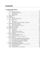
17 1.3 Processor 17 1.4 System Memory 18 1.4.1 Memory Configurations 20 1.5 Intel® 975X Chipset 24 1.5.1 USB 24 1.5.2 IDE Support 25 1.5.3 Real-Time Clock, CMOS SRAM, and Battery 26 1.6 Discrete Serial ATA Interface 27 1.6.1 Serial ATA Controller 27 1.6.2 External Serial ATA Support 27 - Intel S975XBX2 | Product Specification - Page 6
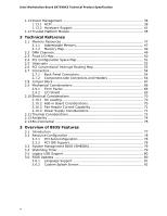
Intel Workstation Board S975XBX2 Technical Product Specification 1.13 Power Management 38 1.13.1 ACPI 38 1.13.2 Hardware Support 41 1.14 Trusted Platform Module 45 2 Technical Reference 2.1 Memory Resources 47 2.1.1 Addressable Memory 47 2.1.2 Memory Map 49 2.2 DMA Channels 49 2.3 Fixed I/O - Intel S975XBX2 | Product Specification - Page 7
(Board Level 98 5.2 Battery Disposal Information 99 Figures 1. Workstation Board Components 14 2. Block Diagram 16 3. Memory of External Serial ATA-Compatible SATA Port 27 10. Front/Back Panel Audio Connector Options for 6-Channel (5.1) Audio Subsystem 32 11. LAN Connector LED Locations - Intel S975XBX2 | Product Specification - Page 8
Workstation Board S975XBX2 Technical Product Specification 22. I/O Shield Dimensions for Boards with the 6-Channel (5.1) Audio Subsystem 69 23. Localized High Temperature Zones 73 Tables 1. Feature Summary 12 2. Manufacturing Options 13 3. Components Shown in Figure 1 15 4. Supported Memory - Intel S975XBX2 | Product Specification - Page 9
Contents 42. BIOS Error Messages 85 43. Port 80h POST Code Ranges 86 44. Port 80h POST Codes 87 45. Typical Port 80h POST Sequence 90 46. Safety Regulations 91 47. Lead-Free Board Markings 96 48. EMC Regulations 97 49. Product Certification Markings 98 ix - Intel S975XBX2 | Product Specification - Page 10
Intel Workstation Board S975XBX2 Technical Product Specification x - Intel S975XBX2 | Product Specification - Page 11
1.1 Overview 12 1.2 Online Support 17 1.3 Processor 17 1.4 System Memory 18 1.5 Intel® 975X Chipset 24 1.6 Discrete Serial ATA Interface 27 1.7 PCI Express Connectors 28 1.8 IEEE-1394a Connectors 29 1.9 Legacy I/O Controller 29 1.10 Audio Subsystem 31 1.11 LAN Subsystem 33 1.12 Hardware - Intel S975XBX2 | Product Specification - Page 12
• Intel® 82975X Memory Controller Hub (MCH) • Intel® 82801GR I/O Controller Hub (ICH7-R) Intel® High Definition Audio subsystem Legacy I/O Control Legacy I/O controller for diskette drive, serial, parallel, and PS/2 ports USB Peripheral Interfaces BIOS Instantly Available PC Technology LAN Support - Intel S975XBX2 | Product Specification - Page 13
powering a fan for the Intel® 82975X Memory Controller Hub (MCH) Processor Core Power Connector One of the following connectors for providing +12 V power to the processor voltage regulator: • 2 x 4-pin (requires a power supply with a dual-rail 2 x 4 power cable). Boards equipped with the 2 x 4-pin - Intel S975XBX2 | Product Specification - Page 14
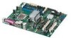
Intel Workstation Board S975XBX2 Technical Product Specification For information about Available configurations for the board 1.1.3 Board Layout Figure 1 shows the location of the major components. Refer to Section 1.2, page 17 Figure 1. Workstation Board Components Table 3 lists the components - Intel S975XBX2 | Product Specification - Page 15
core power connector Memory Controller Hub (MCH) fan header (optional) LGA775 processor socket Intel 82975X MCH DIMM Channel A sockets [2] Processor fan header DIMM Channel B sockets [2] Main power connector Diskette drive connector BIOS Setup configuration jumper block Chassis intrusion header - Intel S975XBX2 | Product Specification - Page 16
ATA IDE Interface Gigabit Ethernet Controller LAN Connector USB Back Panel/Front Panel USB Ports LGA775 Processor Socket System Bus (1066/800 MHz) Primary PCI Express x16 Connector SMBus Secondary PCI Express x16 Connector Intel 975X Chipset PCI Express X16 Interface Intel 82975X Memory - Intel S975XBX2 | Product Specification - Page 17
for the Workstation Board S975XBX2 Processor data sheets ICH7-R/ICH7-DH addressing Custom splash screens Audio software and utilities LAN software and drivers Visit this World Wide Web site: http://www.intel.com/design/motherbd http://support.intel.com/support/motherboards/desktop http - Intel S975XBX2 | Product Specification - Page 18
Intel Workstation Board S975XBX2 Technical Product Specification 1.4 System Memory The board has four DIMM sockets and supports the following memory features: • 1.8 V and 1.9 V DDR2 SDRAM DIMMs • Unbuffered, single-sided or double-sided DIMMs with the following restriction: Double-sided DIMMS with - Intel S975XBX2 | Product Specification - Page 19
used with a 533 MHz system bus frequency processor, the memory will operate at 533 MHz. Table 5 lists the resulting operating memory frequencies based on the combination of DIMMs and processors. Table 5. Memory Operating Frequencies DIMM Type Processor System Bus Frequency DDR2 533 800 MHz DDR2 - Intel S975XBX2 | Product Specification - Page 20
Intel Workstation Board S975XBX2 Technical Product Specification 1.4.1 Memory Configurations The Intel 82975X MCH supports two types of memory organization: • Dual channel (Interleaved) mode. This mode offers the highest throughput for real world applications. Dual channel mode is enabled when the - Intel S975XBX2 | Product Specification - Page 21
Product Description 1.4.1.1 Dual Channel (Interleaved) Mode Configurations Figure 4 shows a dual channel configuration using two DIMMs. In this example, the DIMM0 (blue) sockets of both channels are populated with identical DIMMs. 1 GB 1 GB Channel A, DIMM 0 Channel A, DIMM 1 Channel B, DIMM 0 - Intel S975XBX2 | Product Specification - Page 22
Intel Workstation Board S975XBX2 Technical Product Specification Figure 6 shows a dual channel configuration using four DIMMs. In this example, the combined capacity of the two DIMMs in Channel A equal the combined capacity of - Intel S975XBX2 | Product Specification - Page 23
Product Description 1.4.1.2 Single Channel (Asymmetric) Mode Configurations NOTE Dual channel (Interleaved) mode configurations provide the highest memory throughput. Figure 7 shows a single channel configuration using one DIMM. In this example, only the DIMM0 (blue) socket of Channel A is populated - Intel S975XBX2 | Product Specification - Page 24
Intel Workstation Board S975XBX2 Technical Product Specification 1.5 Intel® 975X Chipset The Intel 975X chipset consists of the following devices: • Intel 82975X Memory Controller Hub (MCH) with Direct Media Interface (DMI) interconnect • Intel 82801GR I/O Controller Hub (ICH7-R) with DMI - Intel S975XBX2 | Product Specification - Page 25
serial ATA IDE connectors that support one device per connector 1.5.2.1 Parallel ATE IDE Interface The ICH7-R's Parallel ATA IDE controller has one bus-mastering Parallel ATA IDE interface. The Parallel ATA IDE interface supports the following modes: • Programmed I/O (PIO): processor controls data - Intel S975XBX2 | Product Specification - Page 26
Intel Workstation Board S975XBX2 Technical Product Specification Native mode is the preferred mode for configurations using the Microsoft Windows* XP and Microsoft Windows 2000 operating systems. NOTE Many Serial ATA controller or the onboard IDE controller (Parallel ATA or Serial ATA memory. BIOS - Intel S975XBX2 | Product Specification - Page 27
Product Description 1.6 Discrete Serial ATA Interface 1.6.1 Serial ATA Controller As a manufacturing option, the board provides a Marvell 88SE6145 Serial ATA (SATA) controller and four connectors (that support one device per connector) for SATA devices. These connectors are in addition to the four - Intel S975XBX2 | Product Specification - Page 28
Intel Workstation Board S975XBX2 Technical Product Specification 1.7 PCI Express Connectors The board provides the following PCI Express connectors: • One Primary PCI Express x16 (electrical x16 or x8) bus add-in card connector. The x16 interface supports simultaneous (full duplex) transfers up to - Intel S975XBX2 | Product Specification - Page 29
-up event interface • PCI Conventional bus power management support The BIOS Setup program provides configuration options for the legacy I/O controller. 1.9.1 Serial Port The board has one serial port connector located on the back panel. The serial port supports data transfers at rates of up to 115 - Intel S975XBX2 | Product Specification - Page 30
Intel Workstation Board S975XBX2 Technical Product Specification For information about The location of the serial port A connector Refer to Figure 15, page 55 1.9.2 Parallel Port The 25-pin D-Sub parallel port connector is located on the back panel. Use the BIOS Setup program to set the parallel - Intel S975XBX2 | Product Specification - Page 31
ratio of 90 dB 1.10.1 Audio Subsystem Software Audio software and drivers are available from Intel's World Wide Web site. For information about Refer to Obtaining audio software and drivers Section 1.2, page 17 1.10.2 Audio Connectors The board contains audio connectors and headers on both - Intel S975XBX2 | Product Specification - Page 32
Intel Workstation Board S975XBX2 Technical Product Specification 1.10.3 6-Channel (5.1) Audio Subsystem The 6-channel (5.1) audio subsystem includes the following: • Intel 82801G I/O Controller Hub (ICH7-R) • SigmaTel 9227 audio codec • Microphone input that supports a single dynamic, condenser, or - Intel S975XBX2 | Product Specification - Page 33
• Advanced packet filtering • Full device driver compatibility • PCI Express Power Management Support The 82573E Gigabit Ethernet Controller supports Alert Standard Format (ASF) 2.0 and Intel Active Management Technology (Intel AMT). 1.11.2 RJ-45 LAN Connector with Integrated LEDs Two LEDs are - Intel S975XBX2 | Product Specification - Page 34
Intel Workstation Board S975XBX2 Technical Product Specification 1.11.3 Alert Standard Format (ASF) Support The board provides the following ASF support for PCI Express x1 bus add-in LAN cards and PCI Conventional bus add-in LAN cards: • Monitoring of system firmware progress events, including: ⎯ - Intel S975XBX2 | Product Specification - Page 35
troubleshooting and recovery that can significantly reduce desk-side visits and potentially increasing efficiency of IT technical staff: ⎯ System event log ⎯ IDE-R or PXE boot; Network drive or remote CD boot ⎯ Serial over LAN ⎯ OOB diagnostics ⎯ Remote control ⎯ Remote BIOS update • Proactive - Intel S975XBX2 | Product Specification - Page 36
Intel Workstation Board S975XBX2 Technical Product Specification 1.11.5 LAN Subsystem Software LAN software and drivers are available from Intel's World Wide Web site. For information about Obtaining LAN software and drivers Refer to Section 1.2, page 17 1.12 Hardware Management Subsystem The - Intel S975XBX2 | Product Specification - Page 37
of the sensors and fan headers. Item Description A Thermal diode, located on processor die B Ambient temperature sensor, internal to hardware monitoring and fan control ASIC C Remote ambient temperature sensor D Processor fan header E Rear chassis fan header F Front chassis fan header - Intel S975XBX2 | Product Specification - Page 38
Intel Workstation Board S975XBX2 Technical Product Specification 1.12.3 Fan Monitoring Fan monitoring can be implemented using Intel Workstation Utilities or third-party software. The level of monitoring and control is dependent on the hardware monitoring ASIC used with the Workstation Board. For - Intel S975XBX2 | Product Specification - Page 39
Product Description Table 7 lists the system states based on how long the power switch is pressed, depending on how ACPI is configured with an ACPI-aware operating system. Table 7. Effects of Pressing the Power Switch If the system is in this state... Off (ACPI G2/G5 - Soft off) On (ACPI G0 - - Intel S975XBX2 | Product Specification - Page 40
Intel Workstation Board S975XBX2 Technical Product Specification Table 8 lists the power states supported by the board along with the associated system power targets. See the ACPI specification Full power > 30 W G1 - sleeping state S1 - Processor stopped C1 - stop grant G1 - sleeping state G1 - - Intel S975XBX2 | Product Specification - Page 41
by default in the BIOS Setup program. Setting this option to Power On will enable a wake-up event from LAN in the S5 state. NOTE The use of these wake-up events from an ACPI state requires an operating system that provides full ACPI support. In addition, software, drivers, and peripherals must - Intel S975XBX2 | Product Specification - Page 42
Intel Workstation Board S975XBX2 Technical Product Specification feature in the BIOS Setup program's Boot board is off or in the S3, S4, or S5 state. • Each fan header is wired to a fan tachometer input of the hardware monitoring and fan control ASIC • All fan headers support closed-loop fan control - Intel S975XBX2 | Product Specification - Page 43
Specification. Add-in boards that also support this specification can participate in power management and can be used to wake the computer. The use of Instantly Available PC technology requires operating system support and PCI 2.2 compliant add-in cards, PCI Express add-in cards, and drivers - Intel S975XBX2 | Product Specification - Page 44
Intel Workstation Board S975XBX2 Technical Product Specification 1.13.2.6 Wake from USB USB bus activity wakes the computer from ACPI S1 or S3 states. NOTE Wake from USB requires the use of a USB peripheral that supports PME enabled in the BIOS). 1.13.2.9 WAKE# Signal Wake-up Support When the WAKE# - Intel S975XBX2 | Product Specification - Page 45
Platform Module (TPM) is a component on the Workstation board that is specifically designed to enhance platform security above-and-beyond the being used unencrypted in plain-text form. The TPM is specifically designed to shield unencrypted keys and platform authentication information from - Intel S975XBX2 | Product Specification - Page 46
- Intel S975XBX2 | Product Specification - Page 47
2.13 Environmental 75 2.1 Memory Resources 2.1.1 Addressable Memory The board utilizes 8 GB of addressable system memory. Typically the address space that is allocated for PCI Conventional bus add-in cards, PCI Express configuration space, BIOS (SPI Flash device), and chipset overhead resides above - Intel S975XBX2 | Product Specification - Page 48
Workstation Board S975XBX2 Technical Product Specification the system memory map. All installed system memory can be used when there is no overlap of system addresses. 8 GB Top of System Address Space FLASH APIC Reserved Upper 4 GB of address space ~20 MB PCI Memory Range contains PCI, chipsets - Intel S975XBX2 | Product Specification - Page 49
(open to the PCI Conventional bus). Dependent on video adapter used. Video memory and BIOS Extended BIOS data (movable by memory manager software) Extended conventional memory Conventional memory 2.2 DMA Channels Table 11. DMA Channels DMA Channel Number 0 1 2 3 4 5 6 7 Data Width 8 or 16 bits - Intel S975XBX2 | Product Specification - Page 50
Intel Workstation Board S975XBX2 Technical Product Specification 2.3 Fixed I/O Map Table 12. I/O Map Address (hex) Size Description 0000 - 00FF 256 bytes Used by the Workstation Board S975XBX2 03F4 - 03F7 1 byte Primary Parallel ATA IDE channel control block 03F8 - 03FF 8 bytes COM1 - Intel S975XBX2 | Product Specification - Page 51
Bus Device Function Number (hex) Number (hex) Number (hex) Description 00 00 00 Memory controller of Intel 82975X component 00 01 00 PCI Express x16 graphics port 00 1B 00 Intel High Definition Audio controller 00 1C 00 PCI Express port 1 00 1C 01 PCI Express port 2 (Gigabit - Intel S975XBX2 | Product Specification - Page 52
Intel Workstation Board S975XBX2 Technical Product Specification 2.5 Interrupts The interrupts can be routed through either the Programmable Interrupt Controller (PIC) or the Advanced Programmable Interrupt Controller (APIC) portion of the ICH7-R/ICH7-DH component. The PIC is supported in Microsoft - Intel S975XBX2 | Product Specification - Page 53
The PCI Conventional specification describes how interrupts sources are electrically tied together on the board and therefore share the same interrupt. bus connector 2 IEEE-1394a controller Discrete SATA Controller ICH7-R/ICH7-DH PIRQ Signal Serial ATA ports, and PCI Express ports are dynamic. 53 - Intel S975XBX2 | Product Specification - Page 54
Intel Workstation Board S975XBX2 Technical Product Specification 2.7 Connectors CAUTION Only the following connectors have computer, the power cable, and the external devices themselves. This section describes the board's connectors. The connectors can be divided into these groups: • Back panel I/O - Intel S975XBX2 | Product Specification - Page 55
the location of the back panel connectors for boards equipped with the 6-channel (5.1) audio subsystem. A D F G B C E HI Item A B C D E F G H I OM18536 Description PS/2 mouse port PS/2 keyboard port Serial port A Parallel port USB ports (four) LAN Audio line in/Retasking Jack C Mic in - Intel S975XBX2 | Product Specification - Page 56
Intel Workstation Board S975XBX2 Technical Product Specification 2.7.2 Component-side Connectors and Headers Figure 16 shows the locations of the component-side connectors and headers. Figure 16. Component-side Connectors and Headers Table - Intel S975XBX2 | Product Specification - Page 57
card connector F Front panel audio header G Primary PCI Express Processor fan header N Main power connector O Diskette drive connector P Chassis intrusion header Q Parallel ATA IDE connector R Serial ATA connector 3 (ICH7-R RAID) S Serial ATA connector 2(ICH7-R RAID) T Serial ATA - Intel S975XBX2 | Product Specification - Page 58
Intel Workstation Board S975XBX2 Technical Product Specification Table 17. ATAPI CD-ROM Connector (Optional) Pin Signal Name 1 Left audio input from CD-ROM 2 CD audio differential ground 3 CD audio differential ground 4 Right audio input from CD-ROM Table 18. Front Panel Audio Header - Intel S975XBX2 | Product Specification - Page 59
21. Chassis Intrusion Header Pin Signal Name 1 Intruder 2 Ground Table 22. SCSI Hard Drive Activity LED Header Pin Signal Name 1 ACT# 2 No connect Table 23. Serial ATA Connectors Pin Signal Name 1 Ground 2 TXP 3 TXN 4 Ground 5 RXN 6 RXP 7 Ground Technical Reference 59 - Intel S975XBX2 | Product Specification - Page 60
Intel Workstation Board S975XBX2 Technical Product Specification 2.7.2.1 Power Supply Connectors The board has three power supply connectors: • Main power - a 2 x 12 connector. The board requires a power supply with a 2 x 12 main power cable. • Processor core power - This connector provides power - Intel S975XBX2 | Product Specification - Page 61
supply remote on/off) 17 Ground 18 Ground 19 Ground 20 No connect 21 +5 V 22 +5 V 23 +5 V 24 Ground Table 25. Processor Core Power Connector (2 x 4 Pin) Pin Signal Name 1 Ground 2 Ground 3 Ground 4 Ground Pin Signal Name 5 +12 V - Rail 1 6 +12 V - Rail 1 7 +12 - Intel S975XBX2 | Product Specification - Page 62
Intel Workstation Board S975XBX2 Technical Product Specification 2.7.2.2 Add-in Card Connectors The board has the following add-in card connectors: • Primary PCI Express x16 (electrical x16 or x8) bus add-in card connector; one connector supporting simultaneous transfers up to 8 GBytes/sec • - Intel S975XBX2 | Product Specification - Page 63
Technical Reference 2.7.2.4 Front Panel Header This section describes the functions of the front panel header. Table 29 lists the signal names of the front panel header. Figure 17 is a connection diagram for the front panel header. Table 29. Front Panel Header Pin Signal In/ Description Pin - Intel S975XBX2 | Product Specification - Page 64
Intel Workstation Board S975XBX2 Technical Product Specification 2.7.2.4.1 Hard Drive Activity LED Header [Orange . Proper LED function requires one of the following: • A Serial ATA hard drive connected to an onboard Serial ATA connector • An IDE hard drive connected to an onboard IDE connector - Intel S975XBX2 | Product Specification - Page 65
7 comprise one USB port. • Pins 2, 4, 6, and 8 comprise one USB port. • Use only a front panel USB connector that conforms to the USB 2.0 specification for high-performance USB devices. One USB Port Power (+5 V DC) D- D+ Ground Key (no pin) 12 3 4 Power (+5 V DC) D- 5 6 D+ 7 8 Ground 10 No - Intel S975XBX2 | Product Specification - Page 66
Intel Workstation Board S975XBX2 Technical Product Specification 2.7.2.6 Front Panel IEEE 1394a Header (Optional) Figure 19 is a connection diagram for the IEEE 1394a header. TPA+ 1 2 TPA- Ground 3 4 Ground TPB+ 5 6 TPB- +12 V DC 7 8 +12 V - Intel S975XBX2 | Product Specification - Page 67
Otherwise, the board could be damaged. Figure 20 shows the location of the jumper block. The 3-pin jumper block determines the BIOS Setup program's and the computer is powered-up, the BIOS compares the processor version and the microcode version in the BIOS and reports if the two match. Figure 20 - Intel S975XBX2 | Product Specification - Page 68
Intel Workstation Board S975XBX2 Technical Product Specification 2.9 Mechanical Considerations 2.9.1 Form Factor The board is designed to fit into an ATX-form-factor chassis. Figure 21 illustrates the mechanical form factor for the board. Dimensions are given in inches [millimeters]. The outer - Intel S975XBX2 | Product Specification - Page 69
board must meet specific dimension and material requirements. Systems based on this board need the back panel I/O shield to pass certification testing. Figure 22 shows the I/O shield for boards with the 6-channel (5.1) audio with the ATX chassis specification are available from Intel. 1.55 REF [0. - Intel S975XBX2 | Product Specification - Page 70
Intel Workstation Board S975XBX2 Technical Product Specification 2.10 Electrical Considerations 2.10.1 DC Loading Table 33 lists the DC loading characteristics of the board. This data is based on a DC analysis of all active components within the board that impact its power delivery subsystems. The - Intel S975XBX2 | Product Specification - Page 71
. Fan Header Current Capability Fan Connector Processor fan Front chassis fan Rear chassis fan depends on the wake devices supported and manufacturing options. System integrators for use with the board. Additional power required in the ATX form factor specification. • The potential relation between - Intel S975XBX2 | Product Specification - Page 72
Intel Workstation Board S975XBX2 Technical Product Specification 2.11 Thermal Considerations This board features a thermal protection circuit in the processor voltage regulator area. This circuit protects the processor voltage regulator from overheating and damaging the board. The thermal protection - Intel S975XBX2 | Product Specification - Page 73
Technical Reference Item A B C D Description Intel 82801G ICH7-R/ICH7-DH Intel 82975X MCH Processor voltage regulator area Processor Figure 23. Localized High Temperature Zones CAUTION Ensure that the ambient temperature does not exceed the board's maximum operating temperature. Failure to do so - Intel S975XBX2 | Product Specification - Page 74
Intel Workstation Board S975XBX2 Technical Product Specification Table 35 provides maximum case temperatures for the as a starting point for the processor voltage regulator area. For information about Intel Pentium 4 processor datasheets and specification updates Refer to Section 1.2, page 17 - Intel S975XBX2 | Product Specification - Page 75
2.13 Environmental Table 36 lists the environmental specifications for the board. Table 36. Environmental Specifications Parameter Temperature Non-Operating Operating Shock Unpackaged Packaged Vibration Unpackaged Packaged Specification -40 °C to +70 °C 0 °C to +55 °C 50 g trapezoidal - Intel S975XBX2 | Product Specification - Page 76
Intel Workstation Board S975XBX2 Technical Product Specification 76 - Intel S975XBX2 | Product Specification - Page 77
Timer 79 3.5 Legacy USB Support 80 3.6 BIOS Updates 80 3.7 Boot Options 81 3.8 BIOS Security Features 83 3.1 Introduction The BIOS is stored in the Serial Peripheral Interface (SPI) Flash device and can be updated using a disk-based program. The SPI contains the BIOS Setup program, POST, the - Intel S975XBX2 | Product Specification - Page 78
Intel Workstation Board S975XBX2 Technical Product Specification Table 37 lists the BIOS Setup program menu features. Table 37. BIOS Setup Program Menu Bar Menu Maintenance Main Function Clears passwords and displays processor information Displays processor and memory configuration Advanced - Intel S975XBX2 | Product Specification - Page 79
data, such as memory size, cache size, and processor clock frequency • Dynamic data, such as event detection and error logging Non-Plug and Play operating systems, such as Microsoft Windows NT*, require an additional interface for obtaining the SMBIOS information. The BIOS supports an SMBIOS table - Intel S975XBX2 | Product Specification - Page 80
Intel Workstation Board S975XBX2 Technical Product Specification 3.5 Legacy USB Support Legacy USB support enables USB devices to be used even when the operating system's USB drivers are not yet available. Legacy USB support is used to access the BIOS Setup program, and to install an operating - Intel S975XBX2 | Product Specification - Page 81
Intel branded logo. For information about Refer to The Intel World Wide Web site Section 1.2, page 17 3.7 Boot Options In the BIOS supported in compliance to the El Torito bootable CD-ROM format specification. Under the Boot menu in the BIOS booting from the onboard LAN or a network add-in card - Intel S975XBX2 | Product Specification - Page 82
Intel Workstation Board S975XBX2 Technical Product Specification 3.7.3 Booting Without Attached Devices For use in embedded applications, the BIOS has been designed so that after passing the POST, the operating system loader is invoked even if the following devices are not present: • Video adapter - Intel S975XBX2 | Product Specification - Page 83
Setup program. This is the user mode. • If only the supervisor password is set, pressing the key at the password prompt of the BIOS Setup program allows the user restricted access to Setup. • If both the supervisor and user passwords are set, users can enter either the supervisor password - Intel S975XBX2 | Product Specification - Page 84
Intel Workstation Board S975XBX2 Technical Product Specification 84 - Intel S975XBX2 | Product Specification - Page 85
85 4.2 BIOS Beep Codes 85 4.3 BIOS Error Messages 85 4.4 Port 80h POST Codes 86 4.1 Speaker The board-mounted speaker BIOS Beep Codes Whenever a recoverable error occurs during POST, the BIOS displays an error message describing the problem (see Table 41). Table 41. Beep Codes Type Memory - Intel S975XBX2 | Product Specification - Page 86
Intel Workstation Board S975XBX2 Technical Product Specification 4.4 Port 80h POST Codes During the POST, the BIOS generates diagnostic by any PEIM/driver for debug. Host Processors: 1F is an unrecoverable CPU error. Memory/Chipset: 2F is no memory detected or no useful memory detected. Recovery: - Intel S975XBX2 | Product Specification - Page 87
processor initialization SMM initialization Chipset Initializing a chipset component Memory Reading SPD from memory DIMMs Detecting presence of memory DIMMs Programming timing parameters in the memory controller and the DIMMs Configuring memory Optimizing memory settings Initializing memory - Intel S975XBX2 | Product Specification - Page 88
Intel Workstation Board S975XBX2 Technical Product Specification Enabling the keyboard Clearing keyboard input buffer Instructing keyboard controller to run Self Test (PS2 only) Mouse memory found Reserved for PEI/PEIMs DXE Core Entered DXE phase Started dispatching drivers Started connecting drivers - Intel S975XBX2 | Product Specification - Page 89
POST Operation DXE Drivers Waiting for user input Checking password Entering BIOS setup Calling service ResetSystem ( ) has been called PEIMs/Recovery Crisis Recovery has initiated per user request Crisis Recovery has initiated by software (corrupt flash) Loading recovery capsule Handing off control - Intel S975XBX2 | Product Specification - Page 90
Intel Workstation Board S975XBX2 Technical Product Specification Table 45. Typical Port 80h POST Sequence POST Code 21 22 23 25 28 34 E4 12 13 50 51 92 90 94 95 EB 58 5A 92 90 94 5A 28 90 94 E7 01 00 Description Initializing a chipset component Reading SPD from memory DIMMs Detecting presence of - Intel S975XBX2 | Product Specification - Page 91
Part 1: General Requirements (International) 5.1.2 European Union Declaration of Conformity Statement We, Intel Corporation, declare under our sole responsibility that the product Intel® Workstation Board S975XBX2 is in conformity with all applicable essential requirements necessary for CE marking - Intel S975XBX2 | Product Specification - Page 92
Intel Workstation Board S975XBX2 Technical Product Specification The product is properly CE marked demonstrating this conformity and is for distribution within all member states of the EU with no restrictions. This product - Intel S975XBX2 | Product Specification - Page 93
the http://www.intel.com/intel/other/ehs/product_ecology/Recycling_Program.htm for the details of this program, including the scope of covered products, available locations, shipping instructions, terms and conditions, etc Intel Product Recycling Program http://www.intel.com/intel/other/ehs - Intel S975XBX2 | Product Specification - Page 94
Intel Workstation Board S975XBX2 Technical Product Specification Deutsch Als Teil von Intels Engagement für den Umweltschutz hat das Unternehmen das Intel Produkt-Recyclingprogramm implementiert, das Einzelhandelskunden von Intel Markenprodukten ermöglicht, gebrauchte Produkte an ausgewählte - Intel S975XBX2 | Product Specification - Page 95
ayrıntılarını ögrenmek için lütfen http://www.intel.com/intel/other/ehs/product_ecology/Recycling_Program.htm Web sayfasına gidin. 5.1.3.3 Lead Free Board This workstation board is lead free although certain discrete components used on the board contain a small amount of lead which is necessary for - Intel S975XBX2 | Product Specification - Page 96
Intel Workstation Board S975XBX2 Technical Product Specification Table 47. Lead-Free Board Markings Description Mark Lead-Free 2nd Level Interconnect: This symbol is used to identify electrical and electronic assemblies and components in which the lead (Pb) - Intel S975XBX2 | Product Specification - Page 97
Regulations Workstation Board S975XBX2 Control Council for Interference from Information Technology Equipment (VCCI). If this is used near a radio or television receiver in a domestic environment, it may cause radio interference. Install and use the equipment according to the instruction manual - Intel S975XBX2 | Product Specification - Page 98
Intel Workstation Board S975XBX2 Technical Product Specification Korean Class B statement translation: this is Communications Authority (ACA) C-tick mark. Includes adjacent Intel supplier code number, N-232. Japan VCCI (Voluntary Control Council for Interference) mark. S. Korea MIC (Ministry - Intel S975XBX2 | Product Specification - Page 99
Regulatory Compliance and Battery Disposal Information 5.2 Battery Disposal Information CAUTION Risk of explosion if the battery is replaced with an incorrect type. Batteries should be recycled where possible. Disposal of used batteries must be in accordance with local environmental regulations. - Intel S975XBX2 | Product Specification - Page 100
Intel Workstation Board S975XBX2 Technical Product Specification equipo. Para deshacerse de las pilas usadas, siga igualmente las instrucciones del fabricante. WAARSCHUWING Er bestaat ontploffingsgevaar als de batterij wordt vervangen door een onjuist - Intel S975XBX2 | Product Specification - Page 101
Regulatory Compliance and Battery Disposal Information OSTRZEŻENIE Istnieje niebezpieczeństwo wybuchu w przypadku zastosowania niewłaściwego typu baterii. Zużyte baterie należy w miarę możliwości utylizować zgodnie z odpowiednimi przepisami ochrony środowiska. PRECAUŢIE Risc de explozie, dacă - Intel S975XBX2 | Product Specification - Page 102
Intel Workstation Board S975XBX2 Technical Product Specification 102
-
 1
1 -
 2
2 -
 3
3 -
 4
4 -
 5
5 -
 6
6 -
 7
7 -
8
-
9
-
10
-
11
-
12
-
13
-
14
-
15
-
16
-
17
-
18
-
19
-
20
-
21
-
22
-
23
-
24
-
25
-
26
-
27
-
28
-
29
-
30
-
31
-
32
-
33
-
34
-
35
-
36
-
37
-
38
-
39
-
40
-
41
-
42
-
43
-
44
-
45
-
46
-
47
-
48
-
49
-
50
-
51
-
52
-
53
-
54
-
55
-
56
-
57
-
58
-
59
-
60
-
61
-
62
-
63
-
64
-
65
-
66
-
67
-
68
-
69
-
70
-
71
-
72
-
73
-
74
-
75
-
76
-
77
-
78
-
79
-
80
-
81
-
82
-
83
-
84
-
85
-
86
-
87
-
88
-
89
-
90
-
91
-
92
-
93
-
94
-
95
-
96
-
97
-
98
-
99
-
100
-
101
-
102
 |
 |

October 2006
Order Number:
D80929-001
The Intel
®
Workstation Board S975XBX2 may contain design defects or errors known as errata that may cause the product to deviate from published specifications.
Current characterized errata are documented in the Intel Workstation Board S975XBX2 Specification Update.
Intel® Workstation Board
S975XBX2
Technical Product Specification