Intel SE7520AF2 User Guide
Intel SE7520AF2 Manual
 |
View all Intel SE7520AF2 manuals
Add to My Manuals
Save this manual to your list of manuals |
Intel SE7520AF2 manual content summary:
- Intel SE7520AF2 | User Guide - Page 1
Intel® Server Board SE7520AF2 User Guide A Guide for Technically Qualified Assemblers of Intel® Identified Subassemblies/Products Order Number: C63389-003 - Intel SE7520AF2 | User Guide - Page 2
product could create a situation where personal injury or death may occur. Intel may make changes to specifications and product descriptions at any time, without notice. Intel server boards contain a number of high-density VLSI and power delivery components that need adequate airflow for cooling - Intel SE7520AF2 | User Guide - Page 3
DDR333 ƒ Intel® Server Management Module "Professional Edition" ƒ Intel® Server Management Module "Advanced Edition" ƒ Processor(s), DDR2-400 system memory DIMMs, hard drive(s), floppy drive, CD-ROM or DVD-ROM drive, RAID controller, operating system Intel® Server Board SE7520AF2 User Guide iii - Intel SE7520AF2 | User Guide - Page 4
Systems List Reference Chassis List Supported Processors Tested Memory List Power Budget Tool Intel® Server Management Software Driver (for an extensive list of drivers available) Operating System Driver (for operating system drivers) Download Finder iv Intel® Server Board SE7520AF2 User Guide - Intel SE7520AF2 | User Guide - Page 5
, make sure that the chassis, power supply, and other modules have passed EMC testing using a server board with a microprocessor from the same family (or higher) and operating at the same (or higher) speed as the microprocessor used on this server board. Intel® Server Board SE7520AF2 User Guide v - Intel SE7520AF2 | User Guide - Page 6
the contacts inside the jumper, causing intermittent problems with the function controlled by that jumper. Take care to grip with, but not squeeze, the pliers or other tool you use to remove a jumper, or you may bend or break the stake pins on the board. vi Intel® Server Board SE7520AF2 User Guide - Intel SE7520AF2 | User Guide - Page 7
any of the instructions. See also Intel Server Boards and Server Chassis Safety Information on the Resource CD and/or at http://support.intel.com/support/motherboards/server/safecert.htm. SAFETY STEPS: Whenever you remove the chassis covers to access the inside of the system, follow these steps - Intel SE7520AF2 | User Guide - Page 8
toute instruction. Consultez Intel Server Boards and Server Chassis Safety Information sur le CD Resource CD ou bien rendez-vous sur le site http://support.intel.com/support/motherboards/server/ . Nous vous recommandons l'usage de gants de protection. viii Intel® Server Board SE7520AF2 User Guide - Intel SE7520AF2 | User Guide - Page 9
las instrucciones. Vea Intel Server Boards and Server Chassis Safety Information en el CD Resource y/o en http://support.intel.com/support/motherboards/server/safecert.htm. INSTRUCCIONES schede e sul telaio. È consigliabile l'uso di guanti di protezione. Intel® Server Board SE7520AF2 User Guide ix - Intel SE7520AF2 | User Guide - Page 10
36 Specific Problems and Corrective Actions 36 Power Light Does Not Light 36 No Characters Appear on Screen 37 Characters Are Distorted or Incorrect 38 System Cooling Fans Do Not Rotate Properly 38 Diskette Drive Activity Light Does Not Light 38 Intel® Server Board SE7520AF2 User Guide xi - Intel SE7520AF2 | User Guide - Page 11
40 Problems with Application Software that Ran Correctly Earlier 40 Devices are not Recognized under Device Manager (Windows* Operating System)...41 Hard Drive(s) are not Recognized 41 Bootable CD-ROM Is Not Detected 41 LED Information ...42 BIOS POST Beep Codes 43 Boot Block Error Beep Codes - Intel SE7520AF2 | User Guide - Page 12
[J1D1 5 Table 3. NIC LEDs ...6 Table 4. Keyboard Commands 24 Table 5. Resetting the System 34 Table 6. LED Descriptions ...42 Table 7. Boot Block Error Beep Codes 43 Table 8. POST Error Beep Codes 44 Table 9. Troubleshooting BIOS Beep Codes 44 Intel® Server Board SE7520AF2 User Guide xiii - Intel SE7520AF2 | User Guide - Page 13
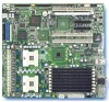
server board. Two versions of this server board are manufactured. One version provides PCI hot plug support that allows you to remove PCI cards from the system without removing the system AC power supply. The hot plug option may not be available in your geography, contact your Intel representative - Intel SE7520AF2 | User Guide - Page 14
ƒ Dual channel architecture ƒ Memory Mirroring and Sparing Chipset Intel® E7520 chipset: ƒ Supports 800 MHz Front Side Bus (FSB) ƒ Intel® E7520 Memory Controller Hub (MCH) ƒ Intel® 6700PHX 64-Bit PCI Hub ƒ Intel® 82801ER I/O Controller Hub5 (ICH-5R) I/O Control Video Hard Disk Drive RAID Super - Intel SE7520AF2 | User Guide - Page 15
multi-speed system fan headers ƒ Two single-speed CPU fan headers ƒ National Semiconductor* PC87431 controller to provide monitoring, alerting and logging of critical sensor information ƒ Intel® Light Guided Diagnostics on critical FRU devices, such as processors, memory, and power ƒ Front panel LCD - Intel SE7520AF2 | User Guide - Page 16
B PCI Slot 5 (PCI-X*, 64-bit/133 MHz) S CPU2 Fault LED JJ Front Panel Control LED Header C PCI Slot 6 (PCI-X*, 64-bit/100 MHz) T CPU2 Fan Header KK SCSI Channel A Header D System Fan 6 Header U CPU1 Socket LL IPMB Header E System Fan 5 Header V CPU2 Socket MM Intel® RAID Activation - Intel SE7520AF2 | User Guide - Page 17
jumpered, the system will attempt to recover the BIOS by loading the BIOS code into the flash device from a bootable recovery device. This jumper is typically used when the BIOS has become corrupted. These pins should not be jumpered for normal operation. Intel® Server Board SE7520AF2 User Guide 5 - Intel SE7520AF2 | User Guide - Page 18
Mbps connection 1000 Mbps connection NOTE Hot-plug SKU only: If the PCI Hot-plug board and the Intel® Server Chassis SC5300 PCI Hot Plug Upgrade kit are installed, the LEDs in the I/O port area provide attention information for PCI slots 1, 3, 4, and 5. 6 Intel® Server Board SE7520AF2 User Guide - Intel SE7520AF2 | User Guide - Page 19
of supported memory DIMMs, see Tested Memory List. The Intel® E7520 chipset includes hardware that supports memory mirroring and memory on-line sparing. Both memory mirroring and memory on-line sparing provide a way to prevent data loss in case a DIMM fails. Intel® Server Board SE7520AF2 User Guide - Intel SE7520AF2 | User Guide - Page 20
44332211 ABABABAB MCH DDDDDDDD IIIIIIII MMMMMMMM MMMMMMMM 44332211 ABABABAB Empty Empty Mirror Primary Figure 5. Four DIMM Memory Mirroring Figure 6. Six DIMM Memory Mirroring Mirror Primary Mirror Primary Figure 7. Eight DIMM Memory Mirroring 8 Intel® Server Board SE7520AF2 User Guide - Intel SE7520AF2 | User Guide - Page 21
spare DIMMs must be equal to or larger than the largest in-service DIMM in that channel. Power Supply A power supply with a minimum rating of 600 Watts is recommended. Your power supply must provide a minimum of 2A of 5V standby current or the board will not boot. Intel® Server Board SE7520AF2 User - Intel SE7520AF2 | User Guide - Page 22
DIMM3B, DIMM3A, DIMM4B, DIMM4A, starting from the edge of the board. DIMM4A is the socket closest to the center of the board. See "System Memory" for a discussion of the memory requirements and options, and Tested Memory List for a list of tested DIMMs. Intel® Server Board SE7520AF2 User Guide 11 - Intel SE7520AF2 | User Guide - Page 23
of the DIMM into the socket. 9. When the DIMM is inserted, push straight down on the top edge of the DIMM until the retaining clips snap into place. Make sure the clips are firmly in place. 10. Replace the server's cover and reconnect the AC power cord. 12 Intel® Server Board SE7520AF2 User Guide - Intel SE7520AF2 | User Guide - Page 24
doing the following: (1) Touch the metal chassis before touching the processor or server board. Keep part of your body in contact with the metal chassis to dissipate the static charge while handling the processor. (2) Avoid moving around unnecessarily. Intel® Server Board SE7520AF2 User Guide 13 - Intel SE7520AF2 | User Guide - Page 25
Socket Lever 6. Align the pins of the processor with the socket, and insert the processor into the socket. ✏ NOTE Make sure the alignment triangle mark and the alignment triangle cutout align correctly. A B A TP00727 Figure 10. Inserting Processor 14 Intel® Server Board SE7520AF2 User Guide - Intel SE7520AF2 | User Guide - Page 26
Hardware Installations and Upgrades 7. Lower the socket lever completely. A TP00728 Figure 11. Closing Socket Lever Intel® Server Board SE7520AF2 User Guide 15 - Intel SE7520AF2 | User Guide - Page 27
the processor. Doing so could damage the processor. 9. Lift the processor lever. 10. Remove the processor. 11. Close the processor lever. 12. If installing a replacement processor, see "Installing the Processor." Otherwise, reinstall the chassis cover. 16 Intel® Server Board SE7520AF2 User Guide - Intel SE7520AF2 | User Guide - Page 28
slot from service before attempting to remove or add a card may result in irreversible damage to the PCI card and / or to your server board. 3. Remove the PCI air duct from its position over the PCI slots and cards. A TP00858 Figure 13. Removing the PCI Air Duct Intel® Server Board SE7520AF2 User - Intel SE7520AF2 | User Guide - Page 29
a hot-plug system, stand the hot-plug curtains on each side of the card to be installed and insert the card between them to prevent accidental contact with adjoining "live" cards. Press firmly on the top edge of the riser card until it is fully seated. 18 Intel® Server Board SE7520AF2 User Guide - Intel SE7520AF2 | User Guide - Page 30
amber LED should be off, to indicate normal operation. 15. Install the PCI air duct over the PCI slots and cards. See your server chassis documentation for instructions. 16. Install the chassis cover. See your server chassis documentation for instructions. Intel® Server Board SE7520AF2 User Guide - Intel SE7520AF2 | User Guide - Page 31
devices connected to the server. Turn off the server. 3. Disconnect the AC power cord from the server. 4. Remove the server cover and locate the battery. 5. Push the metal lever over the top of the battery to the side to disengage it from the battery. 20 Intel® Server Board SE7520AF2 User Guide - Intel SE7520AF2 | User Guide - Page 32
careful to observe the correct polarity, insert it in the battery socket. The negative side of the battery (indicated by the "-") must face the edge of the server board. 9. Close the chassis. 10. Run Setup to restore the configuration settings to the RTC Intel® Server Board SE7520AF2 User Guide 21 - Intel SE7520AF2 | User Guide - Page 33
an operating system being present. See the Intel® Server Board SE7520AF2 Technical Product Specification for details about specific BIOS setup screens. Starting Setup You can enter and start BIOS Setup under several conditions: ƒ When you turn on the server, after POST completes the memory test - Intel SE7520AF2 | User Guide - Page 34
key has a different scan code than the plus key sub-field for multi-valued features like time and date. If a pick list is window is displayed and the user is user is returned to where they were before F10 was pressed without affecting any existing values. 24 Intel® Server Board SE7520AF2 User Guide - Intel SE7520AF2 | User Guide - Page 35
to upgrade the BIOS in flash memory. The code and data in the upgrade file include the following: ƒ On-board system BIOS, including the recovery code, BIOS Setup Utility, and strings. ƒ On-board video BIOS, SCSI BIOS, and other option ROMs for devices embedded on the server board. ƒ OEM binary area - Intel SE7520AF2 | User Guide - Page 36
, covering pins 6 and 7 as indicated in the following diagram. J1D1 1 2 3 CMOS CLEAR BMC Control Force Erase PASSWORD 5 CLEAR Protect 6 Erase 7 RECOVERY 9 BOOT Normal Boot 10 Recovery Boot 11 TP00817 Figure 17. Password Clear Jumper 26 Intel® Server Board SE7520AF2 User Guide - Intel SE7520AF2 | User Guide - Page 37
the AC power and power up the system. 5. When the system begins beeping, power it down and disconnect the AC power. 6. Return the CMOS Clear jumper to cover pins 1 and 2. 7. Close the server chassis, reconnect the AC power and power up the system. Intel® Server Board SE7520AF2 User Guide 27 - Intel SE7520AF2 | User Guide - Page 38
swap controller (HSC), and the field replaceable unit sensor data records (FRU/SDR). See Download Finder for software updates. In addition to the server firmware and files, also update any drivers used for components you have installed in your system, such as video drivers, network drivers, and SCSI - Intel SE7520AF2 | User Guide - Page 39
is no diskette in drive A and no CD-ROM disk in the CD-ROM drive. 5. If the power LED does light, attempt to boot from a floppy diskette or from a CD-ROM disk. 6. Turn on the system. If the power LED does not light, see "Power Light Does Not Light." 28 Intel® Server Board SE7520AF2 User Guide - Intel SE7520AF2 | User Guide - Page 40
the problem, contact your service representative or authorized dealer for help. Power Light Does Not Light Check the following: ‰ Did you press the power-on button? ‰ Is the system operating normally? If so, the power LED might be defective or the cable from the front panel to the server board might - Intel SE7520AF2 | User Guide - Page 41
information is useful for your service representative. 5. If you do not receive a beep code and characters do not appear, the video display monitor or video controller may have failed. Contact your service representative or authorized dealer for help. 30 Intel® Server Board SE7520AF2 User Guide - Intel SE7520AF2 | User Guide - Page 42
that has failed? ‰ Are the fan power connectors properly connected to the server board? ‰ Is the cable from the front panel board connected to the both the front panel board and to the server board? ‰ Are the power supply cables properly connected to the server board? ‰ Are there any shorted wires - Intel SE7520AF2 | User Guide - Page 43
the add-in adapter. The add-in adapter stopped working without apparent cause. ‰ Try reseating the adapter first; then try a different slot if necessary. ‰ The network driver files may be corrupt or deleted. Delete and then reinstall the drivers. 32 Intel® Server Board SE7520AF2 User Guide - Intel SE7520AF2 | User Guide - Page 44
PCI Card System Server Management features require full-time "standby" power. This means some parts of the system have power going to them whenever the power cord is plugged in, even if you have turned the system power off with the power button on the front panel. If you install a PCI card - Intel SE7520AF2 | User Guide - Page 45
. ‰ If using a RAID configuration with SCSI or SATA drives, make sure the RAID card is installed correctly. Bootable CD-ROM Is Not Detected Check the following: ‰ Make sure the BIOS is configured to allow the CD-ROM to be the first bootable device. 34 Intel® Server Board SE7520AF2 User Guide - Intel SE7520AF2 | User Guide - Page 46
1 & 2 Fan Fault CPU 1 & 2 Fault 5v Standby Power LED Display boot 80 POST code Warn on fan failure Identify fan failure Identify processor failure Identify 5v standby power on state Identify the power state of the system Front panel and board left side Inside the system, at the front of each DIMM - Intel SE7520AF2 | User Guide - Page 47
Troubleshooting Description ƒ Off = Slot and card are functioning without error ƒ On = A failure has occurred ƒ Blinking = Slot needs attention BIOS POST Beep Codes The table below lists the POST error beep codes. Prior to system video initialization, the BIOS uses these beep codes to inform users - Intel SE7520AF2 | User Guide - Page 48
Beep Codes In the case of a Bootblock update, where video is not available for text messages to be displayed, speaker beeps are necessary to inform the user of errors. For beep codes associated with a Bootblock update refer to the Intel® Server Board SE7520AF2 Technical Product Specification - Intel SE7520AF2 | User Guide - Page 49
instructions in this guide to power supply, and other modules have passed EMC testing using a server board with a microprocessor from the same family (or higher) and operating at the same (or higher) speed as the microprocessor used on this server board. The final configuration of your end system - Intel SE7520AF2 | User Guide - Page 50
of Conformity (Australia) MED Declaration of Conformity (New Zealand) BSMI Certification (Taiwan) GOST - Listed on one System License (Russia) Belarus - Listed on one System License (Belarus) RRL Certification (Korea) Ecology Declaration (International) 40 Intel® Server Board SE7520AF2 User Guide - Intel SE7520AF2 | User Guide - Page 51
Certification Information Product Regulatory Compliance Markings The Intel Server Baseboard bears the following regulatory marks. RRL MIC Mark GOST-R Mark Australia / New Zealand Korea Russia Electromagnetic Compatibility Notices FCC Verification Statement (USA) This device complies with Part 15 - Intel SE7520AF2 | User Guide - Page 52
radiate radio frequency energy and, if not installed and used in accordance with the instructions, may cause harmful interference to radio communications. However, there is no guarantee that with the CE Mark to illustrate its compliance. VCCI (Japan) 42 Intel® Server Board SE7520AF2 User Guide - Intel SE7520AF2 | User Guide - Page 53
of the Voluntary Control Council for Interference (VCCI) from Information Technology Equipment. If this is used near a radio or television receiver in a domestic environment, it may cause radio interference. Install and use the equipment according to the instruction manual. BSMI (Taiwan) The - Intel SE7520AF2 | User Guide - Page 54
support.intel.com/support/motherboards/server/SE7520AF2 Telephone All calls are billed US $25.00 per incident, levied in local currency at the applicable credit card exchange rate plus applicable taxes. (Intel reserves the right to change the pricing for telephone support at any time (manual toll - Intel SE7520AF2 | User Guide - Page 55
0-800 222 1288. Once connected, dial 800 843 4481 001 916 377 0114 Peru 001 916 377 0114 Uruguay 001 916 377 0114 For an updated support contact list, see http://www.intel.com/support/9089.htm/ 46 Intel® Server Board SE7520AF2 User Guide - Intel SE7520AF2 | User Guide - Page 56
Speed/Stepping/Spec: CPU2 Speed/Stepping/Spec: System BIOS Version: HSC Firmware Version: Chassis Model ˆ Intel SC5300 Base ˆ Intel SC5300LX ˆ Other (Vendor / Model): Board Accessories Installed ˆ PCI Hot-plug Light Pipe ˆ RAID Enabling Accessory ˆ RAID Battery Backup Unit ˆ Intel Management Module - Intel SE7520AF2 | User Guide - Page 57
Peripheral Card or Peripheral Description ˆ PCI-X* Slot 1 ˆ RAID DIMM Slot 2 ˆ PCI Express* Slot 3 ˆ PCI Express* Slot 4 ˆ PCI-X* Slot 5 ˆ PCI-X* Slot 6 Video ˆ On-Board Video ˆ Add-in Video NIC ˆ On-Board NIC1 (10/100/1000 Mb) ˆ On-Board NIC2 (10/100/1000Mb) Driver - Intel SE7520AF2 | User Guide - Page 58
Intel® Server Issue Report Form Complete Problem Description In the space below, provide a complete description of the steps used to reproduce the problem or a complete description of where the problem can be found. Please also include any details on troubleshooting already done. 49
-
 1
1 -
 2
2 -
 3
3 -
 4
4 -
 5
5 -
 6
6 -
 7
7 -
8
-
9
-
10
-
11
-
12
-
13
-
14
-
15
-
16
-
17
-
18
-
19
-
20
-
21
-
22
-
23
-
24
-
25
-
26
-
27
-
28
-
29
-
30
-
31
-
32
-
33
-
34
-
35
-
36
-
37
-
38
-
39
-
40
-
41
-
42
-
43
-
44
-
45
-
46
-
47
-
48
-
49
-
50
-
51
-
52
-
53
-
54
-
55
-
56
-
57
-
58
 |
 |

Intel® Server Board SE7520AF2
User Guide
A Guide for Technically Qualified Assemblers of Intel
®
Identified
Subassemblies/Products
Order Number:
C63389-003