Intel SE7520JR2 User Guide
Intel SE7520JR2 - Server Board Motherboard Manual
 |
UPC - 735858167376
View all Intel SE7520JR2 manuals
Add to My Manuals
Save this manual to your list of manuals |
Intel SE7520JR2 manual content summary:
- Intel SE7520JR2 | User Guide - Page 1
Intel® Server Board SE7520JR2 User Guide Order Number: C51508-001 - Intel SE7520JR2 | User Guide - Page 2
or for any other application in which the failure of the Intel product could create a situation where personal injury or death may occur. Intel may make changes to specifications and product descriptions at any time, without notice. Intel server boards contain a number of high-density VLSI and power - Intel SE7520JR2 | User Guide - Page 3
about which accessories, memory, processors, and third-party hardware have been tested and can be used with your board, and for ordering information for Intel products, see http://support.intel.com/support/motherboards/server/SE7520JR2/compat.htm. Intel® Server Board SE7520JR2 User Guide iii - Intel SE7520JR2 | User Guide - Page 4
about this product, including BIOS settings and chipset information If you just received this product and need to install it Use this Document or Software Intel® Server Board SE7520JR2 Technical Product Specification Intel® Server Board SE7520JR2 Quick Start User's Guide in the product box For - Intel SE7520JR2 | User Guide - Page 5
, make sure that the chassis, power supply, and other modules have passed EMC testing using a server board with a microprocessor from the same family (or higher) and operating at the same (or higher) speed as the microprocessor used on this server board. Intel® Server Board SE7520JR2 User Guide v - Intel SE7520JR2 | User Guide - Page 6
server when handling parts. ESD and handling boards: Always handle boards carefully. They can be extremely sensitive to ESD. Hold boards only by their edges. After removing a board from its protective wrapper or from the server, place the board jumper, causing intermittent problems with the function - Intel SE7520JR2 | User Guide - Page 7
any of the instructions. See also Intel Server Boards and Server Chassis Safety Information on the Resource CD and/or at http://support.intel.com/support/motherboards/server/sb/cs-010770 vorsichtig ausgeführt werden. Sie sollten Schutzhandschuhe tragen. Intel® Server Board SE7520JR2 User Guide vii - Intel SE7520JR2 | User Guide - Page 8
en garde indiquées dans ce document avant de suivre toute instruction. Consultez Intel Server Boards and Server Chassis Safety Information sur le CD Resource CD ou bien rendez-vous sur le site http://support.intel.com/support/motherboards/server/sb/cs-010770.htm. CONSIGNES DE SÉCURITÉ -Lorsque vous - Intel SE7520JR2 | User Guide - Page 9
de las instrucciones. Vea Intel Server Boards and Server Chassis Safety Information en el CD Resource y/o en http://support.intel.com/support/motherboards/server/sb/cs-010770.htm. schede e sul telaio. È consigliabile l'uso di guanti di protezione. Intel® Server Board SE7520JR2 User Guide ix - Intel SE7520JR2 | User Guide - Page 10
Preface x - Intel SE7520JR2 | User Guide - Page 11
Installation 40 First Steps Checklist...40 Hardware Diagnostic Testing 41 Verifying Proper Operation of Key System Lights 41 Confirming Loading of the Operating System 41 Specific Problems and Corrective Actions 42 Power Light Does Not Light 42 Intel® Server Board SE7520JR2 User Guide xi - Intel SE7520JR2 | User Guide - Page 12
47 LED Information ...48 BIOS POST Beep Codes 49 Product Regulatory Compliance 51 Product Safety Compliance 51 Product EMC Compliance - Class A Compliance 51 Certifications / Registrations / Declarations 52 Product Regulatory Compliance Markings 52 Electromagnetic Compatibility Notices - Intel SE7520JR2 | User Guide - Page 13
16 Configuration Jumper 19 NIC LEDs...20 Processor Support 21 DIMM Module Memory Capacity Support 22 Keyboard Commands 35 POST Error Beep Codes 49 Error Beep Codes Provided by Intel® Management Modules 49 Product Certification Markings 52 Intel® Server Board SE7520JR2 User Guide xiii - Intel SE7520JR2 | User Guide - Page 14
Contents xiv - Intel SE7520JR2 | User Guide - Page 15
SE7520JR2SCSID2: On-board SCSI, on-board SATA (RAID), and DDR-2 400MHz ƒ SE7520JR2SCSID1: On-board SCSI, on-board SATA (RAID), and DDR266MHz / DDR333MHz ƒ SE7520JR2SATAD2: On-board SATA (RAID), DDR-2 400MHz ƒ SE7520JR2SATAD1: On-board SATA (RAID), DDR266MHz / DDR333MHz The Server Board SE7520JR2 is - Intel SE7520JR2 | User Guide - Page 16
1. Server Board Features Feature Description Processors Memory Chipset Support for up to two Intel® Xeon™ processors with an 800 MT/s MHz front side bus and frequencies starting at 2.8 GHz. Memory mirroring and memory sparing options Six DIMM slots supporting DDR-2 400MHz memory (SE7520JR2SCSID2 - Intel SE7520JR2 | User Guide - Page 17
-Baseboard Management Controller (mBMC) (Default). Support for optional Intel® Management Module - Advanced Edition or Professional Edition Support for Intel® Server Management 8.x Intel® Light-Guided Diagnostics on all field replaceable units (FRUs) Intel® Server Board SE7520JR2 User Guide 17 - Intel SE7520JR2 | User Guide - Page 18
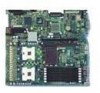
DD ICMB connector I Processor 1 fan header T 50-pin control panel connector EE 120-pin connector for optional Intel® Management Module J Processor socket 1 U 34-pin SSI control panel connector K Processor socket 2 V SATA port 1 Figure 2. Server Board Connector and Component Locations - Intel SE7520JR2 | User Guide - Page 19
Force Erase TP00759 Figure 3. Configuration Jumper Location Table 2. Configuration Jumper Jumper Name Pins What happens at BIOS by loading the above) BIOS code into the flash device from a floppy disk. This jumper is typically used when the BIOS Intel® Server Board SE7520JR2 User Guide 19 - Intel SE7520JR2 | User Guide - Page 20
Server Board Features Back Panel Connectors A B C D E F GH I TP00762 A PS/2 Mouse F Video B PS/2 Keyboard G USB port 1 C Serial Port B H USB port 2 D NIC port 1 (1 Gb) I SCSI channel B E NIC port 2 (1 Gb) Figure 4. Back Panel Connectors The NIC LEDs at the right and left of each - Intel SE7520JR2 | User Guide - Page 21
." Table 4. Processor Support Processor Family FSB Frequency Intel® Xeon™ 800 MHz Intel® Xeon™ 800 MHz Intel® Xeon™ 800 MHz Intel® Xeon™ 800 MHz Intel® Xeon™ 800 MHz Frequency 2.8 GHz 3.0 GHz 3.2 GHz 3.4 GHz 3.6 GHz Memory The Server Board SE7520JR2 provides six DIMM sockets across - Intel SE7520JR2 | User Guide - Page 22
. Refer to the Intel® Server Board SE7520JR2 Technical Product Specification for additional information regarding the memory sub-system. In determining your memory requirements, the need for memory sparing or memory mirroring must be considered. For a complete list of supported memory DIMMs, see the - Intel SE7520JR2 | User Guide - Page 23
than the largest in-service DIMM in that channel. ✏ NOTE Memory mirroring and memory sparing are mutually exclusive. Only one can be active at a time. Refer to the Intel® Server Board SE7520JR2 Technical Product Specification for additional information regarding the memory sub-system. Power Supply - Intel SE7520JR2 | User Guide - Page 24
Disk Drives The Server Board SE7520JR2 supports different hard disk drive options, depending on the version of the server board purchased. ƒ Product codes SE7520JR2SCSID1 and SC7520SCSID2 include connections for utilizing two SCSI channels and two SATA drives. ƒ Product codes SE7520JR2SATAD1 and - Intel SE7520JR2 | User Guide - Page 25
server product, pay close attention to the Safety Information at the beginning of this manual. board. DIMM3A is the socket closest to the processor socket. See "Memory" for a discussion of the memory requirements and options. See "Additional Information and Software" for a link to the list of tested - Intel SE7520JR2 | User Guide - Page 26
's cover. See the documentation that accompanied your server chassis for instructions on removing the server's cover. 5. Locate the DIMM sockets (see Figure 5). DIMM 2A DIMM 3B DIMM 3A DIMM 2B DIMM 1A DIMM 1B Figure 5. Installing Memory TP00761 6. Make sure the clips at either end of the DIMM - Intel SE7520JR2 | User Guide - Page 27
and reconnect any parts you removed or disconnected to reach the DIMM sockets. 8. Replace the server's cover and reconnect the AC power cord. See the documentation that accompanied your server chassis for instructions on installing the server's cover. Intel® Server Board SE7520JR2 User Guide 27 - Intel SE7520JR2 | User Guide - Page 28
Software" for a link to the list of compatible processor(s). ESD and handling processors: Reduce the risk of electrostatic discharge (ESD) damage to the processor by doing the following: (1) Touch the metal chassis before touching the processor or server board. Keep part of your body in contact with - Intel SE7520JR2 | User Guide - Page 29
insert the processor into the socket. ✏ NOTE Make sure the alignment triangle mark and the alignment triangle cutout align correctly. A B A TP00764 Figure 7. Inserting Processor 7. Lower the socket lever completely. TP00765 Figure 8. Closing Socket Lever Intel® Server Board SE7520JR2 User Guide 29 - Intel SE7520JR2 | User Guide - Page 30
the processor, lining up the four captive screws with the four posts surrounding the processor. 3. server. 4. Remove the server's cover. See the documentation that accompanied your server chassis for instructions on removing the server's cover. 5. Unplug the processor fan cable from the server board - Intel SE7520JR2 | User Guide - Page 31
server board is shipped, it is configured to support DSR signals. To change the configuration to support DCD signals a jumper on the board must be changed. Use the following instructions to configure your server board to support Serial Port Configuration Intel® Server Board SE7520JR2 User Guide 31 - Intel SE7520JR2 | User Guide - Page 32
battery on the server board powers the RTC for up to 10 years in the absence of power. When the battery starts to weaken, it loses voltage, and the server settings stored in CMOS RAM in the RTC (for example, the date and time) may be wrong. Contact your customer service representative or dealer - Intel SE7520JR2 | User Guide - Page 33
according to local ordinance. 8. Remove the new lithium battery from its package, and, being careful to observe the correct polarity, insert it in the battery socket. 9. Close the chassis. 10. Run Setup to restore the configuration settings to the RTC. Intel® Server Board SE7520JR2 User Guide 33 - Intel SE7520JR2 | User Guide - Page 34
the Technical Product Specification where you will find details about specific BIOS setup screens. Starting Setup You can enter and start BIOS Setup under several conditions: ƒ When you turn on the server, after POST completes the memory test ƒ When you have moved the CMOS jumper on the server board - Intel SE7520JR2 | User Guide - Page 35
Server Utilities Table 6. Press F5/F6/+ < the full list. On 106-key Japanese keyboards, the plus key has a different scan code than the plus key on the other keyboard, but it has the same effect. Execute affecting any existing values. Intel® Server Board SE7520JR2 User Guide 35 - Intel SE7520JR2 | User Guide - Page 36
to upgrade the BIOS in flash memory. The code and data in the upgrade file include the following: ƒ On-board system BIOS, including the recovery code, BIOS Setup Utility, and strings. ƒ On-board video BIOS, SCSI BIOS, and other option ROMs for devices embedded on the server board. ƒ OEM binary area - Intel SE7520JR2 | User Guide - Page 37
system during the BIOS update process! The system will reset automatically when the BIOS update process is completed. You may encounter a CMOS Checksum error or other problem after reboot. diagram. 23 A B C TP01240 Figure 12. Password Recovery Jumper Intel® Server Board SE7520JR2 User Guide 37 - Intel SE7520JR2 | User Guide - Page 38
server. Clearing the CMOS If you are not able to access the BIOS setup screens, the CMOS Clear jumper will need to be used to reset the configuration RAM Reconnect the AC power, power up the system. 5. When the system begins beeping, power it down and disconnect the AC power. 6. Return the CMOS Clear - Intel SE7520JR2 | User Guide - Page 39
for a link to the software updates. In addition to the server firmware and files, also update any drivers used for components you have installed in your system, such as video drivers, network drivers, and SCSI drivers. Intel provides a package called the "Platform Confidence Test" that may help with - Intel SE7520JR2 | User Guide - Page 40
? ‰ Are all device drivers properly installed? ‰ Are the configuration settings made in Setup correct? ‰ Is the operating system properly loaded? Refer to the operating system documentation. ‰ Did you press the system power on/off switch on the front panel to turn the server on (power on light - Intel SE7520JR2 | User Guide - Page 41
problem. Confirming Loading of the Operating System Once the system boots up, the operating system prompt appears on the screen. The prompt varies according to the operating system. If the operating system prompt does not appear, see "No Characters Appear on Screen" Intel® Server Board SE7520JR2 - Intel SE7520JR2 | User Guide - Page 42
the problem, contact your service representative or authorized dealer for help. Power Light Does Not Light Check the following: ‰ Did you press the power-on button? ‰ Is the system operating normally? If so, the power LED might be defective or the cable from the control panel to the server board - Intel SE7520JR2 | User Guide - Page 43
and contrast controls properly adjusted on the video monitor? See the manufacturer's documentation. ‰ Are the video monitor's signal and power cables properly installed? ‰ Does this video monitor work correctly if plugged into a different system? Intel® Server Board SE7520JR2 User Guide 43 - Intel SE7520JR2 | User Guide - Page 44
the control panel board connected to the both the control panel board and to the server board? ‰ Are the power supply cables properly connected to the server board? ‰ Are there any shorted wires caused by pinched-cables or have power connector plugs been forced into power connector sockets the wrong - Intel SE7520JR2 | User Guide - Page 45
your BIOS is current. See "Additional Information and Software" for a link to the current version. ‰ Make sure the other adapter supports shared interrupts. Make sure your operating system supports shared interrupts. ‰ Try reseating the add-in adapter. Intel® Server Board SE7520JR2 User Guide 45 - Intel SE7520JR2 | User Guide - Page 46
have turned the system power off with the power button on the front panel. If you install a PCI card with the AC power cord plugged in, a signal may be sent to command the system to boot. Before installing a PCI card, you should always: ‰ Turn off the server power by using the power button on the - Intel SE7520JR2 | User Guide - Page 47
. ‰ If using a RAID configuration with SCSI or SATA drives, make sure the RAID card is installed correctly. Bootable CD-ROM Is Not Detected Check the following: ‰ Make sure the BIOS is configured to allow the CD-ROM to be the first bootable device. Intel® Server Board SE7520JR2 User Guide 47 - Intel SE7520JR2 | User Guide - Page 48
Intel® Server Board SE7520JR2 includes LEDs that can aid in troubleshooting your system. A table of these LEDs with a description of their use is listed below. LED Name ID System fault Function Aid in server identification from the back panel Visible fault warning Location Control panel and board - Intel SE7520JR2 | User Guide - Page 49
Troubleshooting BIOS POST Beep Codes The table below lists the POST error beep codes. Prior to system video initialization, the BIOS uses these beep codes to inform users of error conditions. Please note that not all error conditions are supported by BIOS beep codes. Table 7. POST Error Beep Codes - Intel SE7520JR2 | User Guide - Page 50
Troubleshooting 50 - Intel SE7520JR2 | User Guide - Page 51
this product is required to comply with Class A emission requirements as it is intended for a commercial type market place. Intel targets 10db margin to Class A Limits. The Server Board SE7520JR2 has been has been tested and verified to comply with the following electromagnetic compatibility (EMC - Intel SE7520JR2 | User Guide - Page 52
System License (Belarus) ƒ RRL Certification (Korea) ƒ Ecology Declaration (International) Product Regulatory Compliance Markings This product is marked with the following Product Certification Markings: Table 9. Product Certification Markings Regulatory Compliance Country UL Mark USA/Canada - Intel SE7520JR2 | User Guide - Page 53
Electromagnetic Compatibility and used in accordance with the instructions, may cause harmful interference to radio customer is responsible for ensuring compliance of the modified product. Only peripherals (computer input/output devices, terminals, Intel® Server Board SE7520JR2 User Guide 53 - Intel SE7520JR2 | User Guide - Page 54
of Conformity) This product has been tested in accordance too Product 2. Certification No.: On RRL certificate. Obtain certificate from local Intel representative 3. Name of Certification Recipient: Intel Corporation 4. Date of Manufacturer: Refer to date code on product 5. Manufacturer/Nation: Intel - Intel SE7520JR2 | User Guide - Page 55
Regulatory and Compliance Information Intel® Server Board SE7520JR2 User Guide 55 - Intel SE7520JR2 | User Guide - Page 56
support.intel.com/support/motherboards/server/SE7520JR2. Telephone All calls are billed US $25.00 per incident, levied in local currency at the applicable credit card exchange rate plus applicable taxes. (Intel ) 81 298 47 0800 (outside country) Intel® Server Board SE7520JR2 User Guide 56 - Intel SE7520JR2 | User Guide - Page 57
222 1288. Once connected, dial 800 843 4481 Paraguay 001 916 377 0114 Peru 001 916 377 0114 Uruguay 001 916 377 0114 For an updated support contact list, see http://www.intel.com/support/9089.htm/ Intel® Server Board SE7520JR2 User Guide 57 - Intel SE7520JR2 | User Guide - Page 58
- Intel SE7520JR2 | User Guide - Page 59
is available at http://support.intel.com/support/motherboards/server/SE7520JR2/. For the fastest service, please submit your form via the Internet. Date Submitted: Company Name: Contact Name: Email Address: Intel Server Product: Priority (Critical, Hot, High, Low): Brief Problem Description. Provide - Intel SE7520JR2 | User Guide - Page 60
PBA#: Baseboard Serial Number: CPU1 Speed/Stepping/Spec: CPU2 Speed/Stepping/Spec: System BIOS Version: HSC Firmware Version: Chassis Model ˆ Intel SR1400 ˆ Intel SR2400 ˆ Other (Vendor / Model): Operating System Information Operating System Version Service Pack DIMM Configuration DIMM1A MB: DIMM1A - Intel SE7520JR2 | User Guide - Page 61
(10/100/1000 Mb) Hard Drive Information: ˆ ATA # of drives installed: Make/Model/Firmware Revision ˆ SCSI # of drives installed: Hot-swap: Fixed: Make/Model/Firmware Revision ˆ SATA # of drives installed: Make/Model/Firmware Revision Hot-swap: Fixed: Intel® Server Board XYZ User Guide - Intel SE7520JR2 | User Guide - Page 62
Management Information: ˆ On-Board Platform Instrumentation only (Default) ˆ Intel® Management Module - Professional Edition ˆ Intel® Management Module - Advanced Edition Control Panel Information: ˆ Standard Control Panel ˆ Intel® Local Control Panel - Intel SE7520JR2 | User Guide - Page 63
Complete Problem Description In the space below, provide a complete description of the steps used to reproduce the problem or a complete description of where the problem can be found. Please also include any details on troubleshooting already done. Intel® Server Board XYZ User Guide
-
 1
1 -
 2
2 -
 3
3 -
 4
4 -
 5
5 -
 6
6 -
 7
7 -
8
-
9
-
10
-
11
-
12
-
13
-
14
-
15
-
16
-
17
-
18
-
19
-
20
-
21
-
22
-
23
-
24
-
25
-
26
-
27
-
28
-
29
-
30
-
31
-
32
-
33
-
34
-
35
-
36
-
37
-
38
-
39
-
40
-
41
-
42
-
43
-
44
-
45
-
46
-
47
-
48
-
49
-
50
-
51
-
52
-
53
-
54
-
55
-
56
-
57
-
58
-
59
-
60
-
61
-
62
-
63
 |
 |

Intel® Server Board SE7520JR2
User Guide
Order Number:
C51508-001