Intel SPSH4 Product Guide
Intel SPSH4 - Server Platform - 0 MB RAM Manual
 |
UPC - 735858156462
View all Intel SPSH4 manuals
Add to My Manuals
Save this manual to your list of manuals |
Intel SPSH4 manual content summary:
- Intel SPSH4 | Product Guide - Page 1
Intel® SPSH4 Server Platform Product Guide Order Number: A76346-003 A Guide for Technically Qualified Assemblers of Intel® Identified Subassemblies and Products - Intel SPSH4 | Product Guide - Page 2
, provided that all other technology used in combination with said product properly exchanges date data with it. Intel and Intel Xeon are trademarks or registered trademarks of Intel Corporation or its subsidiaries in the United States and other countries. † Third party brands and names are the - Intel SPSH4 | Product Guide - Page 3
...30 Installing Processors, Memory, Hard Disk Drives, and Options 31 Connecting the Monitor, Keyboard, and Mouse 32 Turning On the Server and Running the Power-On Self Test (POST 32 Hot Keys for POST ...33 Configuring the System with the FRU/SDR Load Utility 33 Installing the Service Partition - Intel SPSH4 | Product Guide - Page 4
the Access Cover to the System Boards 68 Installing the Access Cover to the System Boards 68 Removing the Memory Board 69 Installing the Memory Board 70 Removing the Processor Board Air Baffle 71 Installing the Processor Board Air Baffle 72 iv Intel SPSH4 Server Platform Product Guide - Intel SPSH4 | Product Guide - Page 5
the Baseboard 77 Processors ...78 Installing Processors...78 Removing Processors...81 Memory ...82 Installing DIMMs Power Supplies ...90 Checking the Power Status LEDs 90 Removing a Power Supply Module 91 Installing a Power Supply Module 92 PCI Add-In Boards ...93 Operating System Support - Intel SPSH4 | Product Guide - Page 6
Board Set Features 137 Baseboard Connector and Component Locations 138 Baseboard Jumpers...139 Processors ...141 DIMM Memory ...141 Onboard Video ...141 SCSI Controller...141 Network Interface Controllers 142 Network Teaming Features 143 ACPI ...145 vi Intel SPSH4 Server Platform Product Guide - Intel SPSH4 | Product Guide - Page 7
Saving Features 151 Disposal Considerations 151 Disassembly Instructions 151 C Error Messages and Error Codes 153 D Equipment Log and Configuration Worksheets Equipment Log ...161 Calculating Power Consumption 163 Index...165 Figures 1. PSH4 Server (Rack-Mount and Pedestal 29 2. Integrated - Intel SPSH4 | Product Guide - Page 8
Summary...129 11. Front Control Panel Features 133 12. Server Board Set Features 137 13. Boot Block Jumper Descriptions 139 14. Main Jumper Descriptions 140 15. Serial Port B Jumper Descriptions 140 16. Product Regulatory Compliance Markings 148 viii Intel SPSH4 Server Platform Product Guide - Intel SPSH4 | Product Guide - Page 9
17. Regional EMC Compliance Information 149 18. Standard BIOS POST Codes 153 19. Recovery BIOS POST Codes 156 20. BMC Beep Codes...157 21. Error Messages and Codes 157 22. Power Usage Worksheet 1 163 23. Power Usage Worksheet 2 164 Contents ix - Intel SPSH4 | Product Guide - Page 10
x Intel SPSH4 Server Platform Product Guide - Intel SPSH4 | Product Guide - Page 11
access, integrate, configure, and service this product. Intended Application following safety instructions and information. The following safety symbols may be used throughout this product guide, and may has multiple power cords, and all power cords must be unplugged to disconnect AC power or mains - Intel SPSH4 | Product Guide - Page 12
VDE certified cordage to comply with the chassis' safety certifications. The power supply cord(s) is the main disconnect device to AC power. The socket outlet(s) shall be near the equipment and shall till jordat uttag när den ansluts till ett nätverk. 12 Intel SPSH4 Server Platform Product Guide - Intel SPSH4 | Product Guide - Page 13
power supply. There are no serviceable parts in the power supply. Return to manufacturer for servicing. Power Supply Modules CAUTION Power supply server. • Touch the metal on the server chassis before touching the server components. • Keep part of your body in contact with the metal server chassis - Intel SPSH4 | Product Guide - Page 14
lift or move the server by the handles on the power supplies. Equipment Rack Precautions Follow the rack manufacturer's safety and installation instructions for proper rack installation. ground. We recommend you consult your local approved electrician. 14 Intel SPSH4 Server Platform Product Guide - Intel SPSH4 | Product Guide - Page 15
installed in the rack, must not go below 10 °C (50 °F) or rise above 35 °C (95 °F). Extreme fluctuations in temperature may cause a variety of problems in system, and safety limits may be broken. VENTILATION CONSIDERATIONS The equipment rack must provide sufficient airflow to the front of the system - Intel SPSH4 | Product Guide - Page 16
tighten them firmly. 4. Insert and lock the padlock to the system to prevent unauthorized access inside the system. 5. Connect all external cables and the AC power cord(s) to the system. continued 16 Intel SPSH4 Server Platform Product Guide - Intel SPSH4 | Product Guide - Page 17
recommended by the equipment manufacturer. Dispose of used batteries according to manufacturer's instructions. The system is designed to operate in a typical office environment. Choose . • Provided with sufficient space to access the power supply cord(s), because they serve as the product's main - Intel SPSH4 | Product Guide - Page 18
de prévenir tout accès non autorisé à l'intérieur du système. 5. Rebranchez tous les cordons d'alimentation c. a. et câbles externes au système. Suite 18 Intel SPSH4 Server Platform Product Guide - Intel SPSH4 | Product Guide - Page 19
. Remplacer uniquement avec une batterie du même type ou d'un type équivalent recommandé par le fabricant. Disposez des piles usées selon les instructions du fabricant. Le système a été conçu pour fonctionner dans un cadre de travail normal. L'emplacement choisi doit être: • Propre et dépourvu de - Intel SPSH4 | Product Guide - Page 20
, um ein unerlaubtes Öffnen des Systems zu verhindern. 5. Schließen Sie alle externen Kabel und den AC Stromanschlußstecker Ihres Systems wieder an. Fortsetzung 20 Intel SPSH4 Server Platform Product Guide - Intel SPSH4 | Product Guide - Page 21
WARNUNG: Deutsch (Fortsetzung) Der Mikroprozessor und der Kühler sind möglicherweise erhitzt, wenn das System in Betrieb ist. Außerdem können einige Platinen und Gehäuseteile scharfe Spitzen und Kanten aufweisen. Arbeiten an Platinen und Gehäuse sollten vorsichtig ausgeführt werden. Sie sollten - Intel SPSH4 | Product Guide - Page 22
a chiave il lucchetto sul retro del sistema per impedire l'accesso non autorizzato al sistema. 5. Ricollegare tutti i cavi esterni e le prolunghe AC del sistema. continua 22 Intel SPSH4 Server Platform Product Guide - Intel SPSH4 | Product Guide - Page 23
AVVERTENZA: Italiano (Continua) Se il sistema è stato a lungo in funzione, il microprocessore e il dissipatore di calore potrebbero essere surriscaldati. Fare attenzione alla presenza di piedini appuntiti e parti taglienti sulle schede e sul telaio. È consigliabile l'uso di guanti di protezione. - Intel SPSH4 | Product Guide - Page 24
y bloquéelo para impedir que pueda accederse al mismo sin autorización. 5. Conecte todos los cables externos y los cables de alimentación CA al sistema. continuación 24 Intel SPSH4 Server Platform Product Guide - Intel SPSH4 | Product Guide - Page 25
ADVERTENCIAS: Español (Continuación) Si el sistema ha estado en funcionamiento, el microprocesador y el disipador de calor pueden estar aún calientes. También conviene tener en cuenta que en el chasis o en el tablero puede haber piezas cortantes o punzantes. Por ello, se recomienda precaución y el - Intel SPSH4 | Product Guide - Page 26
26 Intel SPSH4 Server Platform Product Guide - Intel SPSH4 | Product Guide - Page 27
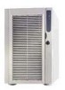
the carrier immediately. • Intel® SPSH4 Server Platform with the following parts installed: SSH4 baseboard SSH4 processor board SSH4 memory board Fan distribution board Front panel board Hot plug indicator board Power distribution board Two 600-W power supplies Four fan modules - Intel SPSH4 | Product Guide - Page 28
28 Intel SPSH4 Server Platform Product Guide - Intel SPSH4 | Product Guide - Page 29
site. 2. Install processors, memory, hard disk drives, and other options. 3. Connect the monitor, keyboard, and mouse. 4. Turn on the server and boot to the System Resource CD-ROM. 5. Configure the system with the FRU/SDR load utility. 6. Install the service partition (optional). 7. Install - Intel SPSH4 | Product Guide - Page 30
, and high-frequency security devices. • Access space provided so the server power cords can be unplugged from the power supply or the wall outlet; this is the only way to remove AC power from the server. • Clearance provided for cooling and airflow. 30 Intel SPSH4 Server Platform Product Guide - Intel SPSH4 | Product Guide - Page 31
Information" on page 149. Installing Processors, Memory, Hard Disk Drives, and Options The server is shipped without processors, memory, or hard drives. To install the memory, processors, hard drives, and other options, follow the steps shown on the Quick Start User Guide that is included with the - Intel SPSH4 | Product Guide - Page 32
configures, and tests the processors, memory, keyboard, and most installed peripheral devices. The length of time needed to complete POST depends on the amount of memory installed and the number of the limited operating system on the System Resource CD. 32 Intel SPSH4 Server Platform Product Guide - Intel SPSH4 | Product Guide - Page 33
the sensor data record (SDR) and field replaceable unit (FRU) inventory for the server. For instructions, see page 62. ✏ NOTE When you first set up your server and any time you change the number of processors, fans, or power supplies, you must run the FRU/SDR load utility. Running FRU/SDR loads the - Intel SPSH4 | Product Guide - Page 34
CD contains documentation, device drivers, utilities, Intel Server Management, and other useful information and software. Most of the documentation is in Adobe† Acrobat† format (PDF) and the CD includes the Adobe Acrobat Reader for viewing the files. 34 Intel SPSH4 Server Platform Product Guide - Intel SPSH4 | Product Guide - Page 35
can browse the contents of the CD, create driver and utility diskettes, and more. • Viewing the Server management software processes signals received from the intrusion switches. Using either the System Setup Utility (page 50) or Intel Server Management (page 49), you can program the system to power - Intel SPSH4 | Product Guide - Page 36
. • Enable Password on Boot. • Disable Secure Mode Boot. To activate: Power on or reset the server. When enabled: The user must enter a password to boot the system. The system boots according to the boot device priority set in BIOS Setup. continued 36 Intel SPSH4 Server Platform Product Guide - Intel SPSH4 | Product Guide - Page 37
section of BIOS Setup. To activate: Power on or reset the server. When enabled: Write protects the master support.intel.com/support/motherboards/server/ssh4/spsh4/compat.htm Install the Rack Mount Kit following the instructions on the back of the Quick Start User Guide and the instructions - Intel SPSH4 | Product Guide - Page 38
38 Intel SPSH4 Server Platform Product Guide - Intel SPSH4 | Product Guide - Page 39
values in battery-backed CMOS; the remainder are stored in flash memory. The values take effect when the system is booted. POST uses up system passwords, specify the boot device sequence, and enable some server management features. Both utilities access the same stored configuration data for - Intel SPSH4 | Product Guide - Page 40
memory, you can use either of these two methods: • Use the front panel buttons: 1. Power down the server. 2. Press the Reset button and hold it down for four seconds or more; while holding down the reset button, press the power the User or Administrator. 40 Intel SPSH4 Server Platform Product Guide - Intel SPSH4 | Product Guide - Page 41
in the server Running SCSISelect To run the SCSISelect utility: 1. During POST, press to run the utility when this message appears on the video monitor: 2. When the main menu for the host adapter appears, follow the instructions on screen - Intel SPSH4 | Product Guide - Page 42
are available, you can download the updates from the Intel support website: http://support.intel.com/support/motherboards/server/ssh4/spsh4 Updates are available in two forms: • A software an already formatted diskette, type: sys a: 5. Press . 42 Intel SPSH4 Server Platform Product Guide - Intel SPSH4 | Product Guide - Page 43
or document files that came with the update. The files from the Web page contain the latest information and instructions for the update, which supercedes the information in this product guide. 3. Record the current BIOS settings. a. Boot the computer and press when you are prompted to do so - Intel SPSH4 | Product Guide - Page 44
power from the BMC. Removing the standby power forces the BMC to reset, which is necessary to complete the update. 5. Reconnect the AC power cord and power up the system. 6. If you are updating the BMC firmware, run the FRU/SDR utility (page 62). 44 Intel SPSH4 Server Platform Product Guide - Intel SPSH4 | Product Guide - Page 45
Record (SDR) load utility is a DOS-based program used to update the server FRU and SDR configuration. The utility is included with the update file. To information and instructions for the update, which supercedes the information in this product guide. 3. Follow the installation instructions that - Intel SPSH4 | Product Guide - Page 46
46 Intel SPSH4 Server Platform Product Guide - Intel SPSH4 | Product Guide - Page 47
features integrated into the server. Processor Sockets Temperature Sensors Power Supplies Fans Chassis Intrusion Memory BMC Nonvolatile storage SEL SDR FRU Front Panel EMP LAN1 Figure 2. Integrated System Management Baseboard Management Controller Intel server boards incorporate a baseboard - Intel SPSH4 | Product Guide - Page 48
processors, or power supplies in the server. Processor fault resilient booting (FRB) failure • Fatal nonmaskable interrupt (NMI) from a source other than the front panel switch • Watchdog timer reset, power down, or power cycle • System restart (reboot) 48 Intel SPSH4 Server Platform Product Guide - Intel SPSH4 | Product Guide - Page 49
the state of the server, diagnose hardware problems, and power on/off or reset the server. • Run the System Setup Utility to change the server configuration. • Run diagnostics tools similar to those used during factory testing. ISM depends on a service partition on the server that you are managing - Intel SPSH4 | Product Guide - Page 50
DOS diskettes, or from the service partition of the hard disk. instructions displayed. Alternatively, if you have a workstation with the Microsoft Windows operating system, you can insert the CD into that system and create the diskettes on that system. 50 Intel SPSH4 Server Platform Product Guide - Intel SPSH4 | Product Guide - Page 51
, you cannot save user preference settings (such as screen colors). The SSU supports ROM-DOS version 6.22. The SSU will not operate from a "DOS Service Partition: Boot the server to the Service Partition (page 32) and execute the following DOS commands: C:\> cd ssu C:\SSU> ssu.bat 2. The mouse driver - Intel SPSH4 | Product Guide - Page 52
password are set and you entered only the user password when you started the SSU. All changes to the admin password take effect immediately. 52 Intel SPSH4 Server Platform Product Guide - Intel SPSH4 | Product Guide - Page 53
writing to the diskette drive while the server is in secure mode. • Power Switch Inhibit: Enable prevents the power and reset buttons from functioning when the server is in secure mode. Disable allows the power and reset buttons to function normally when the server is in secure mode. 3. Click Save - Intel SPSH4 | Product Guide - Page 54
Manager. When you start the SEL Manager, it automatically loads the current list of events from non-volatile memory. 2. Use the and keys to scroll the window contents to the left and right by reading the current FRU entries from the server. 54 Intel SPSH4 Server Platform Product Guide - Intel SPSH4 | Product Guide - Page 55
Manager, it automatically loads the SDR entries from non-volatile memory. The SDR Manager window has a navigation pane on the Intel support website: http://support.intel.com/support/motherboards/server/ssh4/spsh4 Updating the BIOS To update the BIOS: 1. Download the update from the Intel support - Intel SPSH4 | Product Guide - Page 56
Verifying the Firmware To compare the system firmware in nonvolatile memory with a firmware file: 1. Download the update from the Intel support website. 2. From the SSU Main window, choose System Click Save To File and specify a filename and location. 56 Intel SPSH4 Server Platform Product Guide - Intel SPSH4 | Product Guide - Page 57
for the new settings to take effect. Alerting for Platform Events You can set up the server to alert you when various events occur. Alerts can be delivered either as telephone pages or over the LAN. Instructions for setting up both telephone paging alerts and LAN alerts are given below. System - Intel SPSH4 | Product Guide - Page 58
disabled list to enabled the list. • - Intel SPSH4 | Product Guide - Page 59
over the LAN: 1. Configure the remote system to receive alerts. For more information, see the documentation for Intel Server Management software. 2. From the SSU Main window, choose Platform Event Manager (PEM). 3. In the PEM window, click Configure LAN. 4. Select the Enable LAN Alerts check box - Intel SPSH4 | Product Guide - Page 60
address of the router for this server. • Subnet Mask: the IP address for the server's subnet. The server uses this to decide if the alert destination is on the same subnet. 7. Click Save to save the changes. 8. Click Close to return to the PEM window. 60 Intel SPSH4 Server Platform Product Guide - Intel SPSH4 | Product Guide - Page 61
remote modem or serial access: 1. From the SSU Main window, choose Platform Event Manager (PEM). 2. In the PEM window, click Configure EMP. available at any time. • Preboot: the EMP is available only when the server is powered down or is in the running POST during startup. • Disabled: remote systems - Intel SPSH4 | Product Guide - Page 62
server management subsystem's product level FRU and SDR nonvolatile storage. The utility: • Discovers the product configuration based on instructions up your server • Whenever you change the number of power supplies, processors, or fans in the server • When Intel SPSH4 Server Platform Product Guide - Intel SPSH4 | Product Guide - Page 63
with the -d option, information about the specified area is read from memory and displayed. If the given display function fails because of an cases, you'll use the standard configuration file master.cfg that is supplied with the utility on the System Resource CD and with software updates: FRUSDR - Intel SPSH4 | Product Guide - Page 64
information to identify the platform. The utility verifies that a file is being used with the correct server before updating any information in nonvolatile storage. Prior to updating the SDR information, the SDR area in nonvolatile storage is cleared. 64 Intel SPSH4 Server Platform Product Guide - Intel SPSH4 | Product Guide - Page 65
and Removing Components Tools and Supplies Needed • Phillips† screwdriver • Small flat-bladed screwdriver • Extraction tool for processor heat sink clips: Dexter to the server system. You will need this information when running the SSU. Access Covers This section includes instructions for the - Intel SPSH4 | Product Guide - Page 66
cover provides access to the electronics bay, which contains PCI add-in cards and the server board set, and to the power supply bay. To remove the cover: 1. Release the captive screws located on the rear fasteners located on the rear edge of the cover. 66 Intel SPSH4 Server Platform Product Guide - Intel SPSH4 | Product Guide - Page 67
Removing the Front Access Cover The front access cover provides access to the hot-swap fans, to devices in the peripherals bay, and to the hot-swap drive bay. To remove the front access cover: 1. Remove the rear access cover (page 66). 2. Release the two captive cover screws, as shown in Figure 4. - Intel SPSH4 | Product Guide - Page 68
: 1. Orient the access cover with the captive screws toward the front of the server. 2. Insert the tabs on the rear of the cover into the slots at the rear of the chassis. 3. Press down gently and tighten the captive screws at the front of the cover. 68 Intel SPSH4 Server Platform Product Guide - Intel SPSH4 | Product Guide - Page 69
board: 1. Grasp the bracket on the top edge of the memory board and pull straight up until the board disengages from the connector on the processor board (Figure 6). 2. Lift the memory board out of the chassis. OM13385 Figure 6. Removing the Memory Board Installing and Removing Components 69 - Intel SPSH4 | Product Guide - Page 70
into the guides at both ends of the electronics bay. 2. Align the memory board with the connector on the processor board and press down on the bracket until the board is fully inserted into the connector. OM13386 Figure 7. Installing the Memory Board 70 Intel SPSH4 Server Platform Product Guide - Intel SPSH4 | Product Guide - Page 71
Air Baffle To remove the processor board air baffle: 1. At the end of the air baffle closest to the rear of the chassis, press the front of the electronics bay and remove the baffle from the chassis. A OM13387 Figure 8. Removing the Processor Board Air Baffle Installing and Removing Components 71 - Intel SPSH4 | Product Guide - Page 72
Air Baffle To install the processor board air baffle: 1. Orient the baffle so that the two release tabs are toward the rear of the place and the two tabs are engaged. Do not force it down. OM13388 Figure 9. Installing the Processor Board Air Baffle 72 Intel SPSH4 Server Platform Product Guide - Intel SPSH4 | Product Guide - Page 73
Removing the Processor Board To remove the processor board: 1. Rotate the handles on the processor board until they are fully open (Figure 10). 2. Using the handles, tilt the processor board up and remove it from the chassis. OM13389 Figure 10. Removing the Processor Board Installing and Removing - Intel SPSH4 | Product Guide - Page 74
open position, lower the processor board until it rests on the baseboard bracket. 3. Close and press down on the handles until the processor board is fully engaged with the sockets on the baseboard. A Figure 11. Installing the Processor Board OM13390 74 Intel SPSH4 Server Platform Product Guide - Intel SPSH4 | Product Guide - Page 75
Removing the Baseboard To remove the baseboard: 1. Remove all external cables from the baseboard I/O ports at the back of the chassis. 2. Label and disconnect all internal cables connected to the PCI add-in boards. 3. Remove all PCI add-in boards (pages 96 and 98). 4. Plastic curtains run the length - Intel SPSH4 | Product Guide - Page 76
, C). d. Remove the overlay. 8. Remove the six screws, the plastic overlay, and the two processor board mounting brackets that attach the baseboard to the electronics bay (Figure 13, A). A B OM13265 , static-free surface (or in an antistatic bag). 76 Intel SPSH4 Server Platform Product Guide - Intel SPSH4 | Product Guide - Page 77
aligned with their corresponding threaded standoffs in the floor of the electronics bay. 3. Install the processor board mounting brackets and processor-side plastic overlay as follows: a. Align the processor board mounting bracket for the center of the baseboard with the three mounting holes. Insert - Intel SPSH4 | Product Guide - Page 78
This section includes instructions for installing and removing processors and heat sinks. For a list of supported processors, call your service representative or visit the Intel Support website: http://support.intel.com/support/motherboards/server/ssh4/spsh4/ Installing Processors To install - Intel SPSH4 | Product Guide - Page 79
aligns with the triangle on the corner of the socket (Figure 16). 4. Aligning the pins of the processor with the socket, insert the processor into the socket. The processor should drop into the socket without requiring any force. 5. Lower the locking bar completely. OM13268 Figure 16. Installing - Intel SPSH4 | Product Guide - Page 80
instructions packaged with the applicator, apply thermal grease to the processor. 7. Insert the heat sink into the air baffle and place it on top of the processor B Socket and processor D Heat sink retention clips Figure 17. Installing the Heat Sink 80 Intel SPSH4 Server Platform Product Guide - Intel SPSH4 | Product Guide - Page 81
Removing Processors To remove processors: 1. Observe the safety and ESD precautions at the beginning of this document. 2. Remove both heat sink clips as follows: a. Insert the heat sink clip extraction tool (see "Tools and Supplies Needed" on page 65) into the slot at one end of the clip (Figure 18 - Intel SPSH4 | Product Guide - Page 82
This section includes instructions for removing and installing DIMMs on the memory board. For a list of supported memory, call your service representative or visit the Intel Support website: http://support.intel.com/support/motherboards/server/ssh4/spsh4/compat.htm Installing DIMMs CAUTION Use - Intel SPSH4 | Product Guide - Page 83
(Figure 19, A). 4. Orient the DIMM so that the notch in the bottom edge of the DIMM aligns with the keyed socket on the memory board. 5. Insert the bottom edge of the DIMM into the socket and press down firmly on the DIMM until it seats correctly. The plastic ejector - Intel SPSH4 | Product Guide - Page 84
Removing DIMMs 1. Remove the memory board (page 69). Place the board component-side up on a nonconductive, static-free surface. 2. Locate the DIMM you it away from the socket and store it in an antistatic package. B A OM13271 Figure 20. Removing DIMMs 84 Intel SPSH4 Server Platform Product Guide - Intel SPSH4 | Product Guide - Page 85
section describes the LED status indicators for the drive bays and gives instructions for using the drive carriers to install and remove drives. Checking Status LED State Status Solid green The hard drive is present and powered on. Flashing green The hard drive is active. Solid yellow There - Intel SPSH4 | Product Guide - Page 86
hard drive from its wrapper and place it on an antistatic surface. 3. Record the new drive model and serial number in your equipment log. 86 Intel SPSH4 Server Platform Product Guide - Intel SPSH4 | Product Guide - Page 87
4. Place the drive in the carrier with the component side down. 5. Using the four screws removed earlier, attach the drive to the carrier. A B C E D OM13275 A SCA Connector B Drive C Carrier D Plastic Rail E Screw Figure 23. Installing a SCSI Hard Disk Drive in a Carrier Removing a Hot-swap - Intel SPSH4 | Product Guide - Page 88
Carrier 2. Carefully pull on the carrier handle and slide the carrier out of the bay. 3. Install a new drive into the carrier (page 86). OM13392 88 Intel SPSH4 Server Platform Product Guide - Intel SPSH4 | Product Guide - Page 89
4. Hold the carrier handle in the fully open position and slide the carrier into the desired bay. 5. Push the carrier into the drive bay until the carrier handle latch engages the locking slot in the edge of the drive bay (Figure 25, C). 6. Push the handle closed until it clicks into position. C B A - Intel SPSH4 | Product Guide - Page 90
problem. ✏ NOTE If all power supply modules are functioning and all power cables from the power distribution board are properly connected to the baseboard and other components, but the server still won't power on, replace the power distribution board (page 117). 90 Intel SPSH4 Server Platform - Intel SPSH4 | Product Guide - Page 91
resistance you will feel. Use even, steady force to remove the supply. 3. Pull the latch handle to release the power supply module and carefully pull the module out of the power supply bay. 4. Unplug the power cord from the power supply. 5. If you are not going to install a replacement module, you - Intel SPSH4 | Product Guide - Page 92
supply to the chassis. 5. Insert and tighten the four screws that secure the power supply module to the chassis. 6. Connect the AC power cord to the wall outlet or other AC power source. The green LED on the power supply module should be illuminated. 92 Intel SPSH4 Server Platform Product Guide - Intel SPSH4 | Product Guide - Page 93
the latest drivers: http://support.intel.com/support/motherboards/server/ssh4/spsh4/ Without a driver, the operating system does not support hot-plug installation and removal of PCI add-in boards. In that case, you must treat all eight PCI slots as non-hot-plug slots and follow the instructions on - Intel SPSH4 | Product Guide - Page 94
Add-In Boards Table 9 lists the LED states and the hot-plug PCI status indicated by each state. Table 9. LED Hot-Plug PCI Status Indicators Power LED State Status Green Power to slot Amber Fault on slot Not lit No power to slot 94 Intel SPSH4 Server Platform Product Guide - Intel SPSH4 | Product Guide - Page 95
that power to the slot is on, turn it off by using the PCI hot- plug application software on your system (see "Operating System Support for your equipment log. c. Set jumpers or switches according to the manufacturer's instructions. A B A Latch, rear retention mechanism B Latch, front retention - Intel SPSH4 | Product Guide - Page 96
LED for the slot indicates that power to the slot is on, turn it off by using the PCI hot- plug application software on your system (see "Operating System Support for Hot-Plug Add-In If you are installing a new board, follow the instructions on page 95. 96 Intel SPSH4 Server Platform Product Guide - Intel SPSH4 | Product Guide - Page 97
1. Disconnect the AC power cords from the power source or wall outlets. 2. Turn off all peripheral devices connected to the server system. 3. Remove the equipment log. c. Set jumpers or switches according to the manufacturer instructions. 6. Open the latches on the front and rear retention - Intel SPSH4 | Product Guide - Page 98
it free of the retention bracket. 6. If you are installing a new board, follow the instructions on page 97. If you are not installing another PCI add-in board, continue with the to the system. 10. Connect the power cord and turn on power to the server. 98 Intel SPSH4 Server Platform Product Guide - Intel SPSH4 | Product Guide - Page 99
fan modules. CAUTION Don't remove a fan module while the server is powered on unless you have a replacement unit available. Once you remove a fan module from the system, replace it within five minutes. Vacant spaces alter airflow patterns in the server system and can cause overheating and damage to - Intel SPSH4 | Product Guide - Page 100
the fan status LED for the replacement fan. If the installation was successful, the indicator will not be lit. 5. Install the front access cover. 100 Intel SPSH4 Server Platform Product Guide - Intel SPSH4 | Product Guide - Page 101
the real-time clock (RTC) for up to 10 years in the absence of power. When the battery starts to weaken, it loses voltage, and the server settings stored in CMOS RAM in the RTC (for example, the date and time) might be incorrect. For a list of approved replacement batteries, contact your customer - Intel SPSH4 | Product Guide - Page 102
until it locks into the socket. 11. Install the processor board, air baffle, memory board, system board access cover, and the rear access cover. 12. Run BIOS Setup to restore the configuration settings to the RTC. 13. Restore your custom BIOS settings. 102 Intel SPSH4 Server Platform Product Guide - Intel SPSH4 | Product Guide - Page 103
electronics bay. Both the front subchassis and the rear electronics bay swing open. Additionally, you can completely remove them to gain access to the server internal components. You can more easily open and remove the front subchassis and electronics bay if the system is laying on its side (the - Intel SPSH4 | Product Guide - Page 104
until the hinge pins engage the notches. 3. Connect all cables from the front subchassis to the power distribution board and to the baseboard. To install the electronics bay: 1. With the electronics bay the Front Subchassis and Rear Electronics Bay 104 Intel SPSH4 Server Platform Product Guide - Intel SPSH4 | Product Guide - Page 105
Closing the Front Subchassis and Rear Electronics Bay CAUTION Before you close the front subchassis or electronics bay, make sure no cables are pinched or otherwise obstructing the front subchassis and rear electronics bay. Excessive cable stress or chafing can cause cables to disconnect and - Intel SPSH4 | Product Guide - Page 106
board cable C SCSI hard drive cable D IDE peripheral cable E Diskette drive cable F USB and serial port B cables Figure 39. Cables to the Subchassis OM13405 106 Intel SPSH4 Server Platform Product Guide - Intel SPSH4 | Product Guide - Page 107
Figure 40 shows the routing of ribbon cables through the cable clamp. Additional cables are routed behind these ribbon cables, as shown in Figure 41. D A C B A A Diskette drive cable C Front panel board cable B IDE peripheral cable D Cable clamp Figure 40. Front Cables in the Cable Clamp - Intel SPSH4 | Product Guide - Page 108
cable D Cable clamp B Serial port B cable E Fan distribution board cable C Hot-swap back plane cable Figure 41. Rear Cables in the Cable Clamp OM13407 108 Intel SPSH4 Server Platform Product Guide - Intel SPSH4 | Product Guide - Page 109
For a description of the features on the front panel board, see page 133. To replace the front panel board: 1. Turn off power to the server and unplug the AC power cords from the power source. 2. Remove the front access cover (page 67). 3. Remove the fan modules and the foam fan baffle (page 119 - Intel SPSH4 | Product Guide - Page 110
from the inside of the front subchassis. C B A A Power cable C Screw B Data cable OM13413 Figure 43. Replacing the 12. Set any jumpers or switches according to the drive manufacturer instructions. 13. Position the new drive with the component side up Intel SPSH4 Server Platform Product Guide - Intel SPSH4 | Product Guide - Page 111
hole in the front subchassis. 16. Tighten the mounting screw to secure the drive and bracket to the front subchassis. 17. Connect the signal and power cables to the drive. The connectors are keyed to fit only one way. 18. Install the fan baffle and fan modules. 19. Install the front - Intel SPSH4 | Product Guide - Page 112
Drives This section provides information and instructions for installing and removing devices . The number of peripheral drives you can install depends on: • The number supported by the bus • The number of drive bays available • The height of your area. 112 Intel SPSH4 Server Platform Product Guide - Intel SPSH4 | Product Guide - Page 113
Drive To remove a peripheral drive: 1. Turn off power to the server and unplug the AC power cords from the power source. 2. Remove the front access cover (page 67). 3. Remove the fan modules and the foam fan baffle (pages 100 and 119). 4. Disconnect the power and data cables from the back of the - Intel SPSH4 | Product Guide - Page 114
bay. Push the drive into the bay until the slide rails lock in place. 11. Connect the signal and power cables to the drive. You can insert the keyed connectors only one way. 12. Install the foam fan baffle, fan modules, and the front access cover. 114 Intel SPSH4 Server Platform Product Guide - Intel SPSH4 | Product Guide - Page 115
contains a drive carrier with a plastic air baffle. Removing a Hot Swap Drive Bay To remove a drive bay: 1. Turn off power to the server and unplug the AC power cords from the power source. 2. Open and remove the front subchassis (page 103 and 104). 3. Remove the fan modules and the foam fan - Intel SPSH4 | Product Guide - Page 116
Installing a Hot-Swap Drive Bay To install a drive bay: 1. Turn off power to the server and unplug the AC power cords from the power source. 2. Open and remove the front subchassis (page 103 and 104). 105). 10. Install the front access cover (page 67). 116 Intel SPSH4 Server Platform Product Guide - Intel SPSH4 | Product Guide - Page 117
board in your hand about 30° and gently slide the other edge of the board into the four slots in the power supply bays. 11. When the board is inserted all the way into the slots, tilt the board down so the four mounting holes on the edge - Intel SPSH4 | Product Guide - Page 118
13. Install the power supplies. 14. Install the electronics bay (page 104). 15. Connect the cables to the power distribution board and baseboard. 16 ribbon cable and the power cable. 10. Install the fan modules. 11. Install the front access cover. 118 Intel SPSH4 Server Platform Product Guide - Intel SPSH4 | Product Guide - Page 119
Foam Fan Baffle Removing the Foam Fan Baffle To remove the foam fan baffle: 1. Remove the front access cover (page 61). 2. Remove all fan modules from the foam fan baffle (page 88). 3. Remove the fan distribution board (page 118). 4. Gently bend the ends of the foam baffle (Figure 50, A) toward each - Intel SPSH4 | Product Guide - Page 120
rivets down to secure the board to the electronics bay. 8. Connect the ribbon cable to the mating connector on the hot-plug indicator board. 120 Intel SPSH4 Server Platform Product Guide - Intel SPSH4 | Product Guide - Page 121
drivers server on (the power-on light should be lit)? ‰ Are the system power cords properly connected to the system and plugged into a NEMA 6-15R outlet for 100-120 V∼ or for 200-240 V∼? ‰ Is AC power available at the wall outlet? If all items are correct and problems persist, contact your service - Intel SPSH4 | Product Guide - Page 122
are installed. ‰ If the problems are intermittent, there might be a loose cable, dirt in the keyboard (if keyboard input is incorrect), a marginal power supply, or other intermittent component failures a complete list of errors and codes, see page 147. 122 Intel SPSH4 Server Platform Product Guide - Intel SPSH4 | Product Guide - Page 123
in the order given. If you cannot correct the problem, contact your service representative or authorized dealer for assistance. Power Light Does Not Light Check the following: ‰ Are all the power supplies plugged in? Is the power turned on to the power strip or outlet? Do you have a blown fuse or - Intel SPSH4 | Product Guide - Page 124
installed? ‰ Is the correct monitor/video board installed for your operating system? If the problem persists, the video monitor might be faulty or it might be the incorrect type. Contact your service representative or authorized dealer for assistance. 124 Intel SPSH4 Server Platform Product Guide - Intel SPSH4 | Product Guide - Page 125
supply cables properly connected to the baseboard and the fan carrier board assembly? ‰ Are there any shorted wires caused by pinched cables or power connector plugs forced into power connector sockets the wrong way? If the connections are correct, contact your service representative or authorized - Intel SPSH4 | Product Guide - Page 126
The add-in adapter stopped working without apparent cause. ‰ Try reseating the adapter first; then try a different slot if necessary. ‰ The network driver files might be corrupt or deleted. Delete and then reinstall the drivers. ‰ Run the diagnostics. 126 Intel SPSH4 Server Platform Product Guide - Intel SPSH4 | Product Guide - Page 127
customer service representative for assistance. Bootable CD-ROM Is Not Detected Check the following: ‰ Is the BIOS set to allow the CD-ROM to be the first bootable device? ‰ Are the jumpers on the CD-ROM drive set correctly? ‰ Are the power and data cables connected properly? Solving Problems 127 - Intel SPSH4 | Product Guide - Page 128
128 Intel SPSH4 Server Platform Product Guide - Intel SPSH4 | Product Guide - Page 129
specifications of the server. Table 10. Feature Summary Feature Configuration flexibility Description Up to four processors from the Intel® Xeon™ processor family. Eight full length PCI slots (4 PCI-X hot plug, 2 PCI-X non hot plug, 2 PCI non hot plug). Two or Three power supplies. Two Ultra160 - Intel SPSH4 | Product Guide - Page 130
of the server. • The rear access cover provides access to hot-plug PCI boards. • The front access cover provides access to the hot-swap fans. C B A OM13421 A Bezel B Front access cover C Rear access cover Figure 52. SPSH4 Server Hot-Swap Access 130 Intel SPSH4 Server Platform Product Guide - Intel SPSH4 | Product Guide - Page 131
53 shows the chassis with the access covers removed. IJ D H A G B C E F OM13422 A Hot-plug PCI add-in cards B Memory board C Processor board air baffle D Power supply bay E Electronics bay F Fan bay G CD-ROM drive H 5.25-inch peripheral bay I 3.5-inch diskette J Front control panel Figure - Intel SPSH4 | Product Guide - Page 132
Components Figure 54 shows the electronics bay with the access cover, memory board, and air baffle removed. A B C D OM13423 A Hot-plug PCI slots C Baseboard B Non-hot-plug PCI slots D Processor board Figure 54. Electronics Bay Internal Components 132 Intel SPSH4 Server Platform Product Guide - Intel SPSH4 | Product Guide - Page 133
features of the front control panel of the SPSH4 server platform. NM L K J I H A B CD E F G OM13424 Figure 55. SPSH4 Front Control Panel Table 11. Front Control Panel Features Device Operation A Power button To turn power on, press the power button momentarily. If the system is in sleep - Intel SPSH4 | Product Guide - Page 134
PCI-X add-in card slots E Non-hot-plug 32-bit, 33 MHz PCI add-in card slots F Power supply bays G LAN2 Gbit RJ45 connector H USB ports 0 (upper) and 1 (lower) I Video connector J for optional VHDCI SCSI connector Figure 56. SPSH4 Rear Panel View 134 Intel SPSH4 Server Platform Product Guide - Intel SPSH4 | Product Guide - Page 135
a CD-ROM drive installed. CAUTION Intel does not recommend installing a hard server comes with one hot-swap hard drive bay installed. A second bay is available as an accessory. The hard drive bays each support drives that consume up to 20 watts of power. Opening the bezel door provides access to the - Intel SPSH4 | Product Guide - Page 136
drive types, go to: http://support.intel.com/support/motherboards/server/ssh4/spsh4/compat.htm Power Supplies The power supply bay comes with two 600-W power supply modules and can accommodate a third general system fault LED on the front panel is lit. 136 Intel SPSH4 Server Platform Product Guide - Intel SPSH4 | Product Guide - Page 137
. Table 12 lists the major features of the server board set. Table 12. Server Board Set Features Feature Description Processors Up to four processors from the Intel Xeon processor family. Memory 12 dual inline memory module (DIMM) slots support PC-200-compliant registered ECC DDR DRAM DIMMs - Intel SPSH4 | Product Guide - Page 138
accelerator J Intel® 82544 Ethernet controller DD Intelligent Platform Management Bus (IPMB) connector (P12) K Video RAM (VRAM) (4 MB total) EE Adaptec 7899 SCSI controller L Processor board ) Figure 58. Baseboard Connector and Component Locations 138 Intel SPSH4 Server Platform Product Guide - Intel SPSH4 | Product Guide - Page 139
updated. These jumpers are not used for routine firmware updates. Use the boot block jumpers only when the instructions with a firmware update specifically say to do so. When you do need to enable either of these BIOS boot block to be overwritten when updating the BIOS. Server Description 139 - Intel SPSH4 | Product Guide - Page 140
guide (see the references in Table 14). The FRB3 Timer Disable jumper and the BMC Force Update jumper are special purpose jumpers that you should use only when instructed to do so by an Intel support passed to DCD input on UART (DB9 only). 7-8 Spare. 140 Intel SPSH4 Server Platform Product Guide - Intel SPSH4 | Product Guide - Page 141
Processors The SPSH4 accommodates one to four processors from the Intel Xeon processor family. For a complete list of supported processors see: http://support.intel.com/support/motherboards/server/ssh4/spsh4 DIMM Memory The memory board contains twelve 168-pin DIMM slots each supporting 72-bit ECC ( - Intel SPSH4 | Product Guide - Page 142
IEEE 820.3u auto-negotiation support • Chained memory structure similar to the 82559, 82558, 82557 and 82596 • Full duplex support at both 10 Mbps and 100 Mbps operation • Low power +3.3 V device • IP checksum LED indicates 100-Mbps operation when lit. 142 Intel SPSH4 Server Platform Product Guide - Intel SPSH4 | Product Guide - Page 143
. To set up an option, read the instructions in the Windows NT 4.0 or NetWare 4.1x readme files. ✏ NOTE Windows NT versions prior to 4.0 do not support Adapter Teaming options. Adapter Teaming options require NT 4.0 with Service Pack 4.0 or later (or Service Pack 3.0 and the Windows Hot Fix†). In - Intel SPSH4 | Product Guide - Page 144
the adapters as needed. Adapter teams configured for FEC also provide the benefits of AFT. To use FEC, you must have two, four, or eight server adapters installed in your server and linked to the same FEC-enabled Cisco switch. 144 Intel SPSH4 Server Platform Product Guide - Intel SPSH4 | Product Guide - Page 145
some power, so the power supply fans will still run. The server supports sleep states s0, s1, s4, and s5: • s0: Normal running state. • s1: Processor sleep state. No context will be lost in this state and the processor caches will maintain coherency. • s4: Hibernate or Save to Disk: The memory and - Intel SPSH4 | Product Guide - Page 146
146 Intel SPSH4 Server Platform Product Guide - Intel SPSH4 | Product Guide - Page 147
15 (Class A) Electromagnetic Compatibility - Immunity European Union International Korea Russia EN55024: 1998 CISPR 24: 1st Edition MIC Notice 1997-41 GOST-R 50628-95 Power Line Harmonics / Voltage Flicker European Union International Japan EN61000-3-2 / EN61000-3-3 IEC61000-3-2 JEIDA 147 - Intel SPSH4 | Product Guide - Page 148
Compliance Mark BSMI Certification Number BSMI EMC Warning for Class A Devices System Compliance Safety Mark (same for Canada) EMC Compliance Marking Statement - Class A Products 148 Intel SPSH4 Server Platform Product Guide - Intel SPSH4 | Product Guide - Page 149
operation. For questions related to the EMC performance of this product, contact: Intel Corporation 5200 N.E. Elam Young Parkway Hillsboro, OR 97124 1-800-628-8686 This equipment interference. Install and use the equipment according to the instruction manual. continued Regulatory Information 149 - Intel SPSH4 | Product Guide - Page 150
Server Platform 2. Certification No.: Contact Intel representative 3. Name of Certification Recipient: Intel Corporation 4. Date of Manufacturer: Refer to date code on product 5. Manufacturer / Nation: Intel / Refer to manufacturing label on product: 150 Intel SPSH4 Server Platform Product Guide - Intel SPSH4 | Product Guide - Page 151
with all applicable local environmental regulations. Disassembly Instructions This section is intended to aid electronic recyclers in disassembly of Intel products. WARNING Only a technically qualified person shall access, integrate, configure, service, or disassemble this product. Tools needed: see - Intel SPSH4 | Product Guide - Page 152
152 Intel SPSH4 Server Platform Product Guide - Intel SPSH4 | Product Guide - Page 153
10 Initialize Power Management 11 Load alternate registers with initial POST values 12 Restore Processor control memory DIMMs 2A Clear 8 MB base RAM 2C 1-3-4-1 Base RAM failure, BIOS stops execution here if entire memory is bad 32 Test Processor bus-clock frequency 34 Test CMOS 35 RAM - Intel SPSH4 | Product Guide - Page 154
5C Test RAM between 512 and 640k 60 Test extended memory 62 Test extended memory address lines 64 Jump to UserPatch1 66 Configure advanced cache registers 68 Enable external and processor caches errors 7A Test for key lock on continued 154 Intel SPSH4 Server Platform Product Guide - Intel SPSH4 | Product Guide - Page 155
disk controller 92 Jump to UserPatch2 93 Build MPTABLE for multi-processor boards 94 Disable A20 address line 95 Install CD-ROM for two short beeps on checksum failure 9A Shadow option ROMs 9C Set up Power Management 9E Enable hardware interrupts A0 Set time of day A2 Check key - Intel SPSH4 | Product Guide - Page 156
Shadow boot block EF Test system memory F0 Initialize interrupt services F1 Initialize real time clock F2 Initialize video F3 Initialize beeper F4 Initialize boot F5 Restore segment limits to 64 KB F6 Boot mini DOS F7 Boot full DOS 156 Intel SPSH4 Server Platform Product Guide - Intel SPSH4 | Product Guide - Page 157
(processor failure) 1-5-4-2 Power fault: DC power unexpectedly lost (power control failures) 1-5-4-3 Chipset control failure 1-5-4-4 Power RAM error Offset address Shadow RAM Failed Offset address Extended RAM failed Offset address Memory type mixing detected Memory 1 bit error detected Memory - Intel SPSH4 | Product Guide - Page 158
disabled DIMM bank 2 has been disabled Failed Processor 4,n error detected. An error detected in the entire CPU. Memory error, memory bank 1 failed Memory error, memory bank 2 failed 0B62: 0B6F: 0B70: 0B71 error Bad checksum of SROM data continued 158 Intel SPSH4 Server Platform Product Guide - Intel SPSH4 | Product Guide - Page 159
Configuration Data System Configuration Data Read Error Resource Conflict 8503: System Configuration Data Write error Warning: IRQ not configured Incorrect memory speed in location: XX, XX, ... Failure Description Some SMBus device (chip) failed Some SMBus device (chip) failed Some SMBus device - Intel SPSH4 | Product Guide - Page 160
160 Intel SPSH4 Server Platform Product Guide - Intel SPSH4 | Product Guide - Page 161
be required when running the System Setup Utility (SSU). Item System Manufacturer Name and Model Number Serial Number Date Installed Server board set Processor speed and cache Video display Keyboard Mouse Diskette drive A CD-ROM drive (5.25-inch peripheral drive 1) 5.25-inch peripheral - Intel SPSH4 | Product Guide - Page 162
Equipment Log (continued) Item Manufacturer Name and Model Number Serial Number Date Installed 162 Intel SPSH4 Server Platform Product Guide - Intel SPSH4 | Product Guide - Page 163
output of your power supplies. Use the two worksheets in this section to calculate the power used by your Power Usage Worksheet 1 Current (maximum) at voltage level: Device +3.3 V +5 V 5 V Standby Server board set Primary Processor Second Processor Third Processor Fourth Processor Memory - Intel SPSH4 | Product Guide - Page 164
each voltage level to arrive at a total combined power usage on the power supply. Table 23. Power Usage Worksheet 2 Voltage level and total current (V Watts for each voltage level ________ W ________ W ________ W ________ W ________ W ________ W 164 Intel SPSH4 Server Platform Product Guide - Intel SPSH4 | Product Guide - Page 165
balancing, 141 Advanced Configuration and Power Interface, 142 ATI Rage XL memory component, 136 force update jumper, 138 updating firmware, 44 BMC LAN alerts, 49 boot sector, write protecting, 37 booting the server, 32 boot device priority, 52 hot keys, 33 service partition, 33 troubleshooting - Intel SPSH4 | Product Guide - Page 166
97 hard disk drives, 83 PCI add-in boards, 92, 132 power supply modules, 88 hot-swap backplane baseboard connector, 136 hot-swap controller, server, 27 Intel Server Management, 49 Intelligent Platform Management Bus (IPMB) baseboard connector, 136 166 Intel SPSH4 Server Platform Product Guide - Intel SPSH4 | Product Guide - Page 167
LAN2 LED, 131 LEDs fans, 97 front panel, 131 hard disk drives, 83 LAN, 140 PCI add-in boards, 92 power supply modules, 88 rear panel, 132 lifting the server, 14 M memory, 80, 139 memory board, 67 memory test, aborting, 33 modem remote access, 60 monitor, 32 mouse, 32 mouse connector, 132 moving the - Intel SPSH4 | Product Guide - Page 168
service partition hot key, 33 installing, 34 setting up the server, 15, 29 site selection, 29 Sleep button, 131 Software Update Packages, 43 software updates, 42, 55 solving problems, See troubleshooting space requirements, 29 specifications, 127 DIMM memory, 139 physical, 30 power, 30 processors - Intel SPSH4 | Product Guide - Page 169
35 System Setup Utility, See SSU T tools, 63 troubleshooting, 119 application software, 120, 125 bootable CD-ROM not problems, 124 no beep codes, 122 no characters on screen, 122 POST, 120 power light does not light, 121 resetting the system, 119 startup, 119 system fans, 123 U-W unpacking the server - Intel SPSH4 | Product Guide - Page 170
170 Intel SPSH4 Server Platform Product Guide
-
 1
1 -
 2
2 -
 3
3 -
 4
4 -
 5
5 -
 6
6 -
 7
7 -
8
-
9
-
10
-
11
-
12
-
13
-
14
-
15
-
16
-
17
-
18
-
19
-
20
-
21
-
22
-
23
-
24
-
25
-
26
-
27
-
28
-
29
-
30
-
31
-
32
-
33
-
34
-
35
-
36
-
37
-
38
-
39
-
40
-
41
-
42
-
43
-
44
-
45
-
46
-
47
-
48
-
49
-
50
-
51
-
52
-
53
-
54
-
55
-
56
-
57
-
58
-
59
-
60
-
61
-
62
-
63
-
64
-
65
-
66
-
67
-
68
-
69
-
70
-
71
-
72
-
73
-
74
-
75
-
76
-
77
-
78
-
79
-
80
-
81
-
82
-
83
-
84
-
85
-
86
-
87
-
88
-
89
-
90
-
91
-
92
-
93
-
94
-
95
-
96
-
97
-
98
-
99
-
100
-
101
-
102
-
103
-
104
-
105
-
106
-
107
-
108
-
109
-
110
-
111
-
112
-
113
-
114
-
115
-
116
-
117
-
118
-
119
-
120
-
121
-
122
-
123
-
124
-
125
-
126
-
127
-
128
-
129
-
130
-
131
-
132
-
133
-
134
-
135
-
136
-
137
-
138
-
139
-
140
-
141
-
142
-
143
-
144
-
145
-
146
-
147
-
148
-
149
-
150
-
151
-
152
-
153
-
154
-
155
-
156
-
157
-
158
-
159
-
160
-
161
-
162
-
163
-
164
-
165
-
166
-
167
-
168
-
169
-
170
 |
 |

Intel
®
SPSH4 Server Platform
Product Guide
Order Number:
A76346-003
A Guide for Technically Qualified Assemblers of Intel
®
Identified Subassemblies and Products