Intel SR1500AL User Guide
Intel SR1500AL - Server System - 0 MB RAM Manual
 |
View all Intel SR1500AL manuals
Add to My Manuals
Save this manual to your list of manuals |
Intel SR1500AL manual content summary:
- Intel SR1500AL | User Guide - Page 1
Intel® Server System SR1500AL User's Guide A Guide for Technically Qualified Assemblers of Intel® Identified Subassemblies/ Products Intel Order Number D31970-002 - Intel SR1500AL | User Guide - Page 2
required for their specific application and environmental conditions. Intel Corporation can not be held responsible if components fail or the server board does not operate correctly when used outside any of their published operating or non-operating limits. Intel, Intel Pentium, and Intel Xeon are - Intel SR1500AL | User Guide - Page 3
Intel® Server System SR1500AL User's Guide iii - Intel SR1500AL | User Guide - Page 4
§ iv Intel® Server System SR1500AL User's Guide - Intel SR1500AL | User Guide - Page 5
information, feature information, and step by step instructions on how to add and replace components on the server system. For the latest version of this manual, see http:// support.intel.com/support/motherboards/server/chassis/SR1500/. Manual Organization Chapter 1 provides a list of reference - Intel SR1500AL | User Guide - Page 6
• Bridge board, installed in the server system • Optical drive cable, installed in the server system • Chassis intrusion switch, integrated into the server system riser • Attention document, in the server system product box • Quick Start User's Guide, in the server system product box • One 32-6mm - Intel SR1500AL | User Guide - Page 7
• Bridge board, installed in the server system • Optical drive cable, installed in the server system • Chassis intrusion switch, integrated into the server system riser • Attention document, in the server system product box • Quick Start User's Guide, in the server system product box • One 32-6mm - Intel SR1500AL | User Guide - Page 8
viii Intel® Server System SR1500AL User's Guide - Intel SR1500AL | User Guide - Page 9
in this document before performing any of the instructions. See also Intel Server Boards and Server Chassis Safety Information on the Intel® Server Deployment Toolkit 2.0 CD and/or at http://support.intel.com/support/ motherboards/server/sb/cs-010770.htm. Wichtige Sicherheitshinweise Lesen Sie - Intel SR1500AL | User Guide - Page 10
http://support.intel.com/support/motherboards/server/sb/CS-010770.htm 上的 Intel Server Boards and Server Chassis Safety Information(《Intel x Intel® Server System SR1500AL User's Guide - Intel SR1500AL | User Guide - Page 11
. If one is not available, provide some ESD protection by wearing an antistatic wrist strap attached to chassis ground any unpainted metal surface on your server when handling parts. ESD and handling boards: Always handle boards carefully. They can be extremely sensitive to ESD. Hold boards - Intel SR1500AL | User Guide - Page 12
xii Intel® Server System SR1500AL User's Guide - Intel SR1500AL | User Guide - Page 13
ix Instrucciones de seguridad importantes ix Chapter 1: Server System References 1 Chapter 2: Server System Features 3 Chassis Component Identification 6 Internal Components ...6 Configuration Jumpers ...8 RAID Support ...13 Standard Control Panel 14 Intel® Local Control Panel 15 Bezels ...16 - Intel SR1500AL | User Guide - Page 14
.. 56 Installing the Intel® RMM and Intel® RMM NIC 56 Removing the Intel® RMM and Intel® RMM NIC 57 Replacing the Backplane Board 58 Removing the Backplane Board 58 Installing the Backplane Board 59 Installing and Removing the Server Board 62 xiv Intel® Server System SR1500AL User's Guide - Intel SR1500AL | User Guide - Page 15
Properly 90 Drive Activity Light Does Not Light 90 CD-ROM Drive or DVD-ROM Drive Activity Light Does Not Light 90 Cannot Connect to a Server 91 Problems with Network 91 System Boots when Installing PCI Card 92 Intel® Server System SR1500AL User's Guide xv - Intel SR1500AL | User Guide - Page 16
Limited Warranty for Intel® Chassis Subassembly Products 119 Appendix H: Installation/Assembly Safety Instructions 123 English ...123 Deutsch ...125 Français ...127 Español ...129 Chinese ...131 Italiano ...132 Appendix I: Safety Information 135 xvi Intel® Server System SR1500AL User's Guide - Intel SR1500AL | User Guide - Page 17
(ESD 139 Other Hazards ...139 Deutsch ...140 Sicherheitshinweise für den Server 140 Sicherheitshinweise und Vorsichtsmaßnahmen 140 Zielbenutzer der Anwendung 141 Standortauswahl el cable de alimentación 153 Advertencias el acceso al sistema 154 Intel® Server System SR1500AL User's Guide xvii - Intel SR1500AL | User Guide - Page 18
Advertencias sobre el montaje en bastidor 155 Descarga electrostática (ESD 155 Otros riesgos ...156 xviii Intel® Server System SR1500AL User's Guide - Intel SR1500AL | User Guide - Page 19
View with Bezel supporting the Intel® Local Control Panel 24 Figure 16. Removing the Front Bezel 25 Figure 17. Installing the Front Bezel 26 Figure 18. Removing the Server System Cover 27 Figure 19. Installing the Server System Cover 28 Figure 20. Removing the Processor Air Duct 29 Figure - Intel SR1500AL | User Guide - Page 20
Routing ...79 Figure 66. Connecting SATA Cables 80 Figure 67. Cabling Around the Small Air Baffle 81 Figure 68. Diagnostic LED Placement Diagram 102 xx Intel® Server System SR1500AL User's Guide - Intel SR1500AL | User Guide - Page 21
List of Tables Table 1. Server System References 1 Table 2. Intel® Server System SR1500AL Feature Summary 4 Table 3. NIC LED Descriptions 11 Table 4. Setup Menu Key Use 74 Table 5. Power Supply Output Capability 82 Table 6. System Environmental Specifications 83 Table 7. Resetting the System - Intel SR1500AL | User Guide - Page 22
xxii Intel® Server System SR1500AL User's Guide - Intel SR1500AL | User Guide - Page 23
Datasheet Found at: http://support.intel.com/support/motherboards/server/S5000PAL/ Intel® S5000 Server Board Family Server BIOS External Product Specification Found: available to order by contacting your Intel field representative; Intel reference number 19953 ESB2 Baseboard Management Controller - Intel SR1500AL | User Guide - Page 24
/server/S5000PAL/ Intel® System Management Software Found at: http://support.intel.com/support/motherboards/server/sysmgmt/ index.htm For diagnostics test software Diagnostics Found at: http://support.intel.com/support/motherboards/server/S5000PAL/ 2 Intel® Server System SR1500AL User's Guide - Intel SR1500AL | User Guide - Page 25
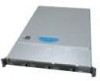
describes the main features of the server system. This chapter provides illustrations of the product, a list of the server system features, and diagrams showing the location of important components and connections on the server system. TP02157 Figure 1. Intel® Integrated Server System SR1500AL - Intel SR1500AL | User Guide - Page 26
mm) wide • 27.25 inches (692 mm) deep • 31 pounds (14.1 kg) - max chassis weight Intel® Server Board S5000PAL Support for up to two Dual-Core Intel® Xeon® processors 5000 sequence • Eight DIMM slots supporting stacked DDR2 533/667 MHz FBDIMM memory • Support for up to 32 GB DDR2 533/667 MHz FBDIMM - Intel SR1500AL | User Guide - Page 27
W power supply module • Six 4-pin fan headers supporting two processor fans, and four system fans • Two non-redundant fans in power supply • Two front panel USB ports • One internal USB header providing two USB ports Intel® System Management Software Intel® Server System SR1500AL User's Guide 5 - Intel SR1500AL | User Guide - Page 28
) J. Processor air duct K. Fan module L. Bridge board M. Control panel (standard control panel shown) N. Hard drive bays (drives not included) O. Slimline Optical Drive Bay (drive not included) P. Front bezel (optional) Figure 2. ChassisComponents 6 Intel® Server System SR1500AL User's Guide - Intel SR1500AL | User Guide - Page 29
. Intel® RMM NIC Connector LL. System Recovery Jumpers OO. Intel® Local Control Panel Header JJ. SATA SW RAID 5 Activation Key Connector MM. Chassis Intrusion Switch Header PP. Serial A Header Figure 3. Server Board Connector and Component Locations Intel® Server System SR1500AL User's Guide 7 - Intel SR1500AL | User Guide - Page 30
Normal Operation (Default) Jumper Name BIOS Select TP02087 Jumper Purpose If pins 1-2 are jumpered, the BIOS in the lower bank will be selected on the next reset. These pins should be jumpered on 2-3 for normal operation. Figure 4. BIOS Select Jumper 8 Intel® Server System SR1500AL User's Guide - Intel SR1500AL | User Guide - Page 31
on the next reset. These pins should be jumpered on 1-2 for normal operation. BMC Force Update Mode If pins 2-3 are jumpered, BMC Force Update Mode is enabled. These pins should be jumpered on 1-2 for normal operation. Figure 5. Recovery Jumpers Intel® Server System SR1500AL User's Guide 9 - Intel SR1500AL | User Guide - Page 32
Intel® Light Guided Diagnostics The server board contains diagnostic LEDs to help you identify failed and failing components, and to help you identify the server from among several servers. Except for the ID LED, the status LED, and the 5V standby LED, the LEDs turn on (amber) only if a failure - Intel SR1500AL | User Guide - Page 33
network connection Network connection in place Transmit/receive activity 10 Mbps connection (if left LED is on or blinking) 100 Mbps connection 1000 Mbps connection Intel® Server System SR1500AL User's Guide 11 - Intel SR1500AL | User Guide - Page 34
support for RAID Activation Key D. Fan 5 Power E. Bridge Board Connector F. Fan 4 Power G. Fan 3 Power H. Fan 2 Power I. Front Panel Connector J. Fan 1 Power K. Screw L. Front Panel USB M. Backplane Connectors Figure 8. Active Backplane Components 12 Intel® Server System SR1500AL User's Guide - Intel SR1500AL | User Guide - Page 35
SAS and SATA support. Both systems can be configured for RAID 0, 1, and 10. The Intel® Server System SR1500ALSAS can be configured for SW RAID 5 by using the Intel® RAID Activation Key AXXRAKSW5 accessory. For information on configuring RAID, see the RAID software user's guide that is included - Intel SR1500AL | User Guide - Page 36
system identification is active. No light indicates system identification is not activated. Turns on/off the system identification LED. Reboots and initializes the system. 14 Intel® Server System SR1500AL User's Guide - Intel SR1500AL | User Guide - Page 37
server in a halt-state for diagnostic purposes. Allows you to attach a video monitor to the front of the chassis. The front and rear video ports cannot be used at the same time. Figure 10. Standard Control Panel Intel off / is in ACPI S4 or S5 state. Intel® Server System SR1500AL User's Guide 15 - Intel SR1500AL | User Guide - Page 38
. The other is used for a chassis with the other Intel® Local Control Panel. Each bezel provides a lock to secure the hard drive and optical drive area. For instructions on installing either of the front bezels, see "Installing the Front Bezel". The order numbers for the bezels are: • ADWBEZBLACK - Intel SR1500AL | User Guide - Page 39
Interface (optional) F. IO module external connector (optional) G. USB 1 connector H. USB 2 connector I. Video connector J. NIC 1 connector K. NIC 2 connector L. RJ45 serial B port M. PS2 keyboard connector Figure 12. Server System Back TP02155 Intel® Server System SR1500AL User's Guide 17 - Intel SR1500AL | User Guide - Page 40
used. For instructions on installing hard drives, see "Installing and Removing a Hot-swap Hard Drive". Note: Drives can consume up to 17 watts of power each. Drives must be specified to run at a maximum ambient temperature of 45C. Note: The Intel® Server System SR1500AL does not support all SAS or - Intel SR1500AL | User Guide - Page 41
Intel® Server System SR1500AL does not support all slimline optical drives. See "Server System References" for an Internet link to a list of supported hardware. Intel on. Instructions for installing your chassis into a rack are included in the rail kit. Intel® Server System SR1500AL User's Guide 19 - Intel SR1500AL | User Guide - Page 42
20 Intel® Server System SR1500AL User's Guide - Intel SR1500AL | User Guide - Page 43
with your server product, pay close attention to the "Safety Information" at the beginning of this manual. Tools Intel® Server System SR1500AL in a rack. The options are the fixed bracket kit, the basic rail kit, and the tool-less rail kit. Only the tool-less rail kit allows you to service the server - Intel SR1500AL | User Guide - Page 44
of the chassis with the finger tab facing outward and located closer to the rear of the chassis. 4. Align the holes in the rail with the tabs on the chassis and place the rail against the chassis. 5. attach the other rail assembly to the other side. 22 Intel® Server System SR1500AL User's Guide - Intel SR1500AL | User Guide - Page 45
and service server chassis) with the outer rail assemblies (attached to the rack). 9. Engage the matching rails and slide the server chassis into the rack until the two safety stops lock into position. 10. Depress the two safety locks (one on each side). Intel® Server System SR1500AL User's Guide - Intel SR1500AL | User Guide - Page 46
. If you are installing a bezel on your server system, make sure you position it as shown. TP02197 Figure 14. Front View with Bezel supporting the Standard Control Panel TP02198 Figure 15. Front View with Bezel supporting the Intel® Local Control Panel 24 Intel® Server System SR1500AL User's Guide - Intel SR1500AL | User Guide - Page 47
Removing the Front Bezel Use the steps below if your system includes a front bezel. 1. Unlock the bezel. 2. Disconnect any cables attached to the control panel. 3. Pull the bezel from the server system. Figure 16. Removing the Front Bezel TP02199 Intel® Server System SR1500AL User's Guide 25 - Intel SR1500AL | User Guide - Page 48
Intel® Local Control Panel. The front bezel is optional. 1. At each end of the bezel, line up the center notch on the bezel with the center guide on the rack handles. 2. Push the bezel onto the front of the server of the server. Before removing the chassis cover, power down the server and unplug all - Intel SR1500AL | User Guide - Page 49
"A"). 3. (Optional) Insert the safety screw at the center of the top cover (see letter "B") if required. 4. Reconnect all peripheral devices and the AC power cord(s). Intel® Server System SR1500AL User's Guide 27 - Intel SR1500AL | User Guide - Page 50
". 2. Power down the server and unplug all peripheral devices and the AC power cable. 3. Remove the server system cover. For instructions, see "Removing the System Cover". 4. Lift the processor air duct from its location over the two processor sockets. 28 Intel® Server System SR1500AL User's Guide - Intel SR1500AL | User Guide - Page 51
TP02201 Figure 20. Removing the Processor Air Duct Intel® Server System SR1500AL User's Guide 29 - Intel SR1500AL | User Guide - Page 52
. Use caution not to pinch or disengage cables that may be near or under the air duct. 7. Install the server system cover. For instructions, see "Installing the System Cover". 8. Plug all peripheral devices and the AC power cable(s) into the server. 30 Intel® Server System SR1500AL User's Guide - Intel SR1500AL | User Guide - Page 53
off all peripheral devices connected to the server. Turn off the server. 3. Disconnect the AC power cord(s) from the server. 4. Remove the system's cover. For instructions, see "Removing the System Cover". 5. Locate the DIMM sockets (see Figure 23). Intel® Server System SR1500AL User's Guide 31 - Intel SR1500AL | User Guide - Page 54
C1 Socket DIMM C2 Socket DIMM D1 Socket DIMM D2 Socket D A C B Figure 23. Installing the Memory TP02072 6. Make sure the clips at either end of the DIMM socket(s) are pushed outward to the open in place (see letter "D" in the figure above). 32 Intel® Server System SR1500AL User's Guide - Intel SR1500AL | User Guide - Page 55
To install a processor, follow these instructions: 1. Observe the safety and ESD precautions in "Safety Information". 2. Turn off all peripheral devices connected to the server. Turn off the server. 3. Disconnect the AC power cord(s) from the server. Intel® Server System SR1500AL User's Guide 33 - Intel SR1500AL | User Guide - Page 56
pins; they are very sensitive and easily damaged. 9. Line up the alignment marks on the processor and the socket, and insert the processor into the socket. Note: Make sure the alignment triangle mark and the alignment triangle cutout align correctly. 34 Intel® Server System SR1500AL User's Guide - Intel SR1500AL | User Guide - Page 57
the processor. 2. Loosely screw in the captive screws on the heat sink corners in a diagonal manner. Do no fully tighten one screw before tightening another. 3. Gradually and equally tighten each captive screw until each is firmly tightened. Intel® Server System SR1500AL User's Guide 35 - Intel SR1500AL | User Guide - Page 58
. See the documentation that came with your server chassis for instructions on removing the server's cover. 5. Loosen the four captive screws on the corners of the heat sink. 6. Twist the heat sink slightly to break the seal between the heat sink and the processor. 7. Lift the heat sink from the - Intel SR1500AL | User Guide - Page 59
processor socket and reinstall the system's cover. Removing and Installing the Small Air Baffle Some installation processes will require that you remove the small air baffle that is placed behind the hard drive bays, near the front of your server your server system with the small air baffle in - Intel SR1500AL | User Guide - Page 60
". 2. Power down the server and unplug all peripheral devices and the AC power cable(s). 3. Remove the server system cover. For instructions, see "Removing the System into the server system. 2. Snap the baffle into place as shown in the figure below. 38 Intel® Server System SR1500AL User's Guide - Intel SR1500AL | User Guide - Page 61
For instructions, see "Removing the Front Bezel". 2. Open the latch at the front of the hard drive carrier. See letter "A" in the figure below. 3. Pull out on the black lever and slide the carrier from the server system. See letter "B" in the figure below. Intel® Server System SR1500AL User's Guide - Intel SR1500AL | User Guide - Page 62
antistatic surface. 6. Set any jumpers and/or switches on the drive according to the drive manufacturer's instructions. 7. With the drive circuit-side down, position the connector end of the drive so that it is attached to the plastic retention device. 40 Intel® Server System SR1500AL User's Guide - Intel SR1500AL | User Guide - Page 63
Install the server system cover. For instructions, see "Installing the System Cover". 12. (Optional) Install the front bezel. For instructions, see "Installing the Front Bezel". 13. Plug all peripheral devices and the AC power cable(s) into the server. Intel® Server System SR1500AL User's Guide 41 - Intel SR1500AL | User Guide - Page 64
the server system cover. For instructions, see "Installing the System Cover". 10. (Optional) Install the front bezel. For instructions, or replacing the drive, you must first take the server out of service, turn off all peripheral devices connected to the Intel® Server System SR1500AL User's Guide - Intel SR1500AL | User Guide - Page 65
For instructions, see "Removing the Front Bezel". 4. Remove the server system cover. For instructions, 10. Insert the optical drive tray assembly into the server system as shown in Figure 35. 11. Verify the cable to the interposer board and the server board. 13. (Optional) For installing the optional - Intel SR1500AL | User Guide - Page 66
the front bezel if it is installed. For instructions, see "Removing the Front Bezel". 4. Remove the server system cover. For instructions, see "Removing the System Cover". 5. optical drive tray assembly from the server system as shown in Figure 36. 44 Intel® Server System SR1500AL User's Guide - Intel SR1500AL | User Guide - Page 67
Assembly from the Server System 7. Press downward on the side of the tray (see letter "A") and disengage the drive from the two metal tabs on the opposite side of the tray. 8. Slide the optical drive out (see letter "B") to remove it from the tray. Intel® Server System SR1500AL User's Guide 45 - Intel SR1500AL | User Guide - Page 68
Server System Bays A filler panel, drive blank, or empty drive carrier must be installed into an empty drive bay. To access the drive bays, remove the front bezel if it is installed. For instructions carriers into any remaining empty hard drive bays. 46 Intel® Server System SR1500AL User's Guide - Intel SR1500AL | User Guide - Page 69
the AC power cable(s). 3. Remove the server system cover. For instructions, see "Removing the System Cover". 4. Remove the processor air duct by lifting straight up. 5. A B AF000358 Figure 38. Removing PCI Riser Assembly from the Server System Intel® Server System SR1500AL User's Guide 47 - Intel SR1500AL | User Guide - Page 70
the Processor Air Duct". 7. Install the server system cover. For instructions, see "Installing the System Cover". 8. (Optional) Install the front bezel. For instructions, see "Installing the Front Bezel". 9. Plug all peripheral devices and the AC power cable(s) into the server. 48 Intel® Server - Intel SR1500AL | User Guide - Page 71
first take the server out of service, turn off all server system cover. For instructions, see "Removing the System Cover". 4. Remove the processor air duct. For instructions, see "Removing the Processor server system (see letter "C" in the figure below). Intel® Server System SR1500AL User's Guide 49 - Intel SR1500AL | User Guide - Page 72
the processor air duct. For instructions, see "Installing the Processor Air Duct". 15. Install the server system cover. For instructions, see "Installing the System Cover". 16. Plug all peripheral devices and the AC power cable(s) into the server. 50 Intel® Server System SR1500AL User's Guide - Intel SR1500AL | User Guide - Page 73
cables to add-in cards that require them. See your add-in card documentation for information and add-in card requirements. 15. Re-install the processor air duct. For instructions, see "Installing the Processor Air Duct". Intel® Server System SR1500AL User's Guide 51 - Intel SR1500AL | User Guide - Page 74
server system cover. For instructions, see "Removing the System Cover". 4. Remove the processor air duct. For instructions, see "Removing the Processor Air Duct". 5. Remove the PCI riser assembly. For instructions slots have filler panels installed. 52 Intel® Server System SR1500AL User's Guide - Intel SR1500AL | User Guide - Page 75
8. Close both retention clips. Note: Make sure that all empty add-in card slots have filler panels installed. 9. Install the PCI riser assembly into the server system. For instructions, see "Installing the PCI Riser Assembly". Intel® Server System SR1500AL User's Guide 53 - Intel SR1500AL | User Guide - Page 76
10. Install the processor air duct. For instructions, see "Installing the Processor Air Duct". 11. Install the server system cover. For instructions, see "Installing the System Cover". 12. Plug all peripheral devices and the AC power cable(s) into the server. Installing and Removing the I/O - Intel SR1500AL | User Guide - Page 77
back panel (see letter "C" in the figure below). B A C AF000749 Figure 45. Removing the I/O Expansion Module(s) from the Server Board 8. Install the PCI riser assembly into the server system. For instructions, see "Installing the PCI Riser Assembly". Intel® Server System SR1500AL User's Guide 55 - Intel SR1500AL | User Guide - Page 78
see "Installing the Processor Air Duct". 10. Install the server system cover. For instructions, see "Installing the System Cover". 11. Plug all peripheral devices and the AC power cable(s) into the server. Installing and Removing the Intel® Remote Management Module and the Intel® RMM NIC Installing - Intel SR1500AL | User Guide - Page 79
Intel® RMM NIC Module from the Server System 9. Install the PCI riser assembly into the server system. For instructions, see "Installing the PCI Riser Assembly". 10. Install the processor air duct. For instructions, see "Installing the Processor Air Duct". Intel® Server System SR1500AL User's Guide - Intel SR1500AL | User Guide - Page 80
the server. Replacing the Backplane Board The instructions server board (see letter "A" in the figure below), and lifting straight up (see letter "B" in the figure below). B B A A AF000373 Figure 48. Removing the Bridge Board from the Server System 58 Intel® Server System SR1500AL User's Guide - Intel SR1500AL | User Guide - Page 81
"Safety Information". 2. Power down the server and unplug all peripheral devices and the AC power cable(s). 3. Remove the server system cover. For instructions, see "Removing the System Cover". in place and tighten the captive screw (see letter "D"). Intel® Server System SR1500AL User's Guide 59 - Intel SR1500AL | User Guide - Page 82
B A C D AF000371 Figure 50. Installing the Backplane into the Server System 6. Connect cables as necessary to the backplane board. 60 Intel® Server System SR1500AL User's Guide - Intel SR1500AL | User Guide - Page 83
place. B A C A C AF000372 Figure 51. Installing the Bridge Board into the Server System 8. Install the server system cover. For instructions, see "Installing the System Cover". 9. Plug all peripheral devices and the AC power cable(s) into the server. Intel® Server System SR1500AL User's Guide 61 - Intel SR1500AL | User Guide - Page 84
, see "Removing the System Cover". 4. Remove the processor air duct. For instructions, see "Removing the Processor Air Duct". 5. Remove the PCI riser assembly. For instructions, see "Removing the PCI Riser Assembly". 6. Place the server board into the server system as shown in the figure below (see - Intel SR1500AL | User Guide - Page 85
assembly. For instructions, see "Removing the PCI Riser Assembly". 6. Remove the six screws from the server board (see letter "A") and lift the server board from the server system (see letter "B"). A B AF000380 Figure 53. Removing the Server Board Intel® Server System SR1500AL User's Guide 63 - Intel SR1500AL | User Guide - Page 86
instructions, see "Installing the PCI Riser Assembly". 9. Install the processor air duct. For instructions, see "Installing the Processor Air Duct". 10. Install the server system cover. For instructions käytetty paristo valmistajan ohjeiden mukaisesti. 64 Intel® Server System SR1500AL User's Guide - Intel SR1500AL | User Guide - Page 87
ordinance. 8. Remove the new lithium battery from its package, and, being careful to observe the correct polarity, insert it in the battery socket. 9. Close the chassis. 10. Run Setup to restore the configuration settings to the RTC. Intel® Server System SR1500AL User's Guide 65 - Intel SR1500AL | User Guide - Page 88
must first take the server out of service, turn off all Server System 5. Insert the replacement power supply module into the power supply cage until it clicks into place. B A B AF000367 Figure 56. Installing Power Supply Module into the Server System 66 Intel® Server System SR1500AL User's Guide - Intel SR1500AL | User Guide - Page 89
server system cover. For instructions, see "Installing the System Cover". 7. Plug all peripheral devices and the AC power cable(s) into the server. Replacing the Control Panel The steps for replacing the standard control panel and the Intel must first take the server out of service, turn off all - Intel SR1500AL | User Guide - Page 90
Install the server system cover. For instructions, see "Installing the System Cover". 11. (Optional) Install the front bezel. For instructions, see "Installing the Front Bezel". 12. Plug all peripheral devices and the AC power cable(s) into the server. 68 Intel® Server System SR1500AL User's Guide - Intel SR1500AL | User Guide - Page 91
or replacing a fan, you must first take the server out of service, turn off all peripheral devices connected to the system, the server and unplug all peripheral devices and the AC power cable(s). 3. Remove the server system cover. For instructions, Intel® Server System SR1500AL User's Guide 69 - Intel SR1500AL | User Guide - Page 92
. For instructions, see "Removing the System Cover". 4. Align the rack handle with the two holes on the side of the server system as shown in the figure below. 5. Attach the rack handle to the server system with two screws as shown in the figure below. 70 Intel® Server System SR1500AL User's Guide - Intel SR1500AL | User Guide - Page 93
"Removing the Front Bezel". 4. Remove the server system cover. For instructions, see "Removing the System Cover". 5. Remove the two screws holding the rack handle in place, and remove the rack handle from the server system as shown in the figure below. Intel® Server System SR1500AL User's Guide 71 - Intel SR1500AL | User Guide - Page 94
AF000378 Figure 62. I Removing the Rack Handle 6. Install the server system cover. For instructions, see "Installing the System Cover". 7. Plug all peripheral devices and the AC power cable(s) into the server. 72 Intel® Server System SR1500AL User's Guide - Intel SR1500AL | User Guide - Page 95
for a link to the Intel® 5000 Series Chipsets Server Board Family Datasheet where you will find details about specific BIOS setup screens. Starting Setup You can enter and start BIOS Setup under several conditions: • When you turn on the server, after POST completes the memory test. • When you have - Intel SR1500AL | User Guide - Page 96
"Setup Menu Key Use" describes the keyboard commands you can use in the BIOS Setup menus. Table 4. Setup Menu Key Use Key to Press Description Pressing to where they were before was pressed without affecting any existing field values. 74 Intel® Server System SR1500AL User's Guide - Intel SR1500AL | User Guide - Page 97
unlikely event that a BIOS error occurs during the BIOS update process, a recovery process may need to be followed to return the system to service. See "Server System References" for a link to necessary software and instrutions. Recording the Current BIOS Settings 1. Boot the computer and press - Intel SR1500AL | User Guide - Page 98
"Server System References" for a link to the update software. Note: Review the instructions and release notes that are provided in the readme file distributed with the BIOS image file before attempting a BIOS upgrade. The release notes contain critical information regarding jumper settings, specific - Intel SR1500AL | User Guide - Page 99
the Password Clear jumper to the Password Clear Protect position, covering pins 1 and 2. 6. Close the server chassis. 7. Reconnect the AC power and power up the server. 8. The password is now cleared and can be reset by going into BIOS setup. Clearing the CMOS If you are not able to access the - Intel SR1500AL | User Guide - Page 100
seconds. 5. Return the CMOS Clear jumper to the CMOS Clear by BMC location, covering pins 1 and 2. 6. Close the server chassis. 7. Reconnect the AC power and power up the system. 8. The CMOS is now cleared and can be reset by going into the BIOS setup. 78 Intel® Server System SR1500AL User's Guide - Intel SR1500AL | User Guide - Page 101
correct cable routing. BC A Intel® Remote Management Module (optional) B Intel® RMM NIC Module (optional) C I/O Module (optional) D Power Supply E Bridge Board F Backplane Board (active shown) G Power to Server Board (Auxiliary.) H Power to Server Board (Main) I Power to Server Board (CPU) J Power - Intel SR1500AL | User Guide - Page 102
SATA Connections Use the figure below to determine the proper SATA cabling. 012 A A 012 B Figure 66. Connecting SATA Cables AF000375 80 Intel® Server System SR1500AL User's Guide - Intel SR1500AL | User Guide - Page 103
B A AF000376 Figure 67. Cabling Around the Small Air Baffle 600W Single Power Supply Input Voltages • 100-127V at 50/60 Hz; 8.55 A max. • 200-240V at 50/60 Hz; 4.3 A max. Intel® Server System SR1500AL User's Guide 81 - Intel SR1500AL | User Guide - Page 104
Watts for the +5 V and +3.3 V outputs. Exceeding a combined 90 Watts will overload the power subsystem and may cause the power supplies to overheat and malfunction. 82 Intel® Server System SR1500AL User's Guide - Intel SR1500AL | User Guide - Page 105
System Environmental Specifications Table 6. System Environmental Specifications Temperature Non-operating Operating Humidity Non-operating Shock Operating Packaged Acoustic noise Electrostatic level. Tested to 15 kilovolts (kV); no component damage. Intel® Server System SR1500AL User's Guide 83 - Intel SR1500AL | User Guide - Page 106
84 Intel® Server System SR1500AL User's Guide - Intel SR1500AL | User Guide - Page 107
System References" for a link to the software updates. In addition to the server firmware and files, also update any drivers used for components you have installed in your system, such as video drivers, network drivers, and SATA drivers. Intel provides a package called the "Platform Confidence Test - Intel SR1500AL | User Guide - Page 108
problem you are experiencing is with a specific software application, see "Problems drivers memory, and chassis lists, as well as the supported hardware and operating system list. See "Server System References" for links to the tested component lists. 86 Intel® Server System SR1500AL User's Guide - Intel SR1500AL | User Guide - Page 109
Light". • If system LEDs are illuminated, see "Make sure the BIOS is configured to allow the CD-ROM to be the first bootable of the light and steps to take to correct the problem. Confirming Loading of the Operating System Once the system boots Intel® Server System SR1500AL User's Guide 87 - Intel SR1500AL | User Guide - Page 110
specific problems the problem, contact your service processor(s) and re-seat them. • Make sure the chassis standoffs are installed only below mounting holes. Misplaced standoffs can contact the pins on the bottom of the server board and cause a short. 88 Intel® Server System SR1500AL User's Guide - Intel SR1500AL | User Guide - Page 111
enabled in the BIOS? • Remove all memory DIMMs have been populated according to the system requirements. • Remove the memory DIMMs and re-seat them. • Make sure the processor(s) comply with the system requirements. • Make sure the processor service Intel® Server System SR1500AL User's Guide 89 - Intel SR1500AL | User Guide - Page 112
• Are any other control panel LEDs lit? • Have any of the fan motors stopped? Use the server management subsystem to check the fan status. • Have your fans speeded up in response to an overheating set correctly? • Is the drive properly configured? 90 Intel® Server System SR1500AL User's Guide - Intel SR1500AL | User Guide - Page 113
adapter supports shared interrupts. Make sure your operating system supports shared interrupts. • Try reseating the add-in adapter. The add-in adapter stopped working without apparent cause • Reseat the adater. • Put the adapter in a different slot. Intel® Server System SR1500AL User's Guide 91 - Intel SR1500AL | User Guide - Page 114
device drivers installed. If the problems persist, contact the software vendor's customer service representative. Problems with Application Software that Ran Correctly Earlier Problems that the software. Make sure all necessary files are installed. 92 Intel® Server System SR1500AL User's Guide - Intel SR1500AL | User Guide - Page 115
• If using a RAID configuration with SCSI or SATA drives, make sure the RAID card is installed correctly. Bootable CD-ROM Disk Is Not Detected Check the following: • Make sure the BIOS is configured to allow the CD-ROM to be the first bootable device. Intel® Server System SR1500AL User's Guide 93 - Intel SR1500AL | User Guide - Page 116
LED Information The Intel® Server Board S5000PAL includes LEDs that can aid in troubleshooting your system. A table of these supported by BIOS beep codes. Table 9. POST Error Beep Codes Number of Beeps 1, 2, or 3 4 - 7 or 9 - 11 8 Reason for Beeps and Action to Take Memory error. Reseat the memory - Intel SR1500AL | User Guide - Page 117
or CPU 1 socket is empty. Reseat or replace the failed processor. In a two-processor system, make sure the processors are identical. Front-side bus select configuration error. DC power unexpectedly lost. Chipset control failure. Power control failure. Intel® Server System SR1500AL User's Guide 95 - Intel SR1500AL | User Guide - Page 118
96 Intel® Server System SR1500AL User's Guide - Intel SR1500AL | User Guide - Page 119
at http:// support.intel.com/support/motherboards/server/chassis/SR1500/. For the fastest service, please submit your form via the Internet. Date Submitted Company Name Contact Name Email Address Intel Server Product Priority (Critical, Hot, High, Low Brief Problem Description. Provide - Intel SR1500AL | User Guide - Page 120
/ part number DIMM D2 MB and Vendor / part number Operating System Information Operating System Version Service Pack Add-in Card, Peripheral, Video, NIC Check each box below as applicable, and provide the requested information. Peripheral Card or Peripheral Description Driver Revision - Intel SR1500AL | User Guide - Page 121
Make/Model Driver Revision IRQ I/O Base FW Address Revision Hot-swap or Fixed IRQ FW Revision Management Information On-Board Platform Instrumentation only Intel® Remote Management Module Control Panel Information Standard Control Panel Intel® Local Control Panel Intel® Server System - Intel SR1500AL | User Guide - Page 122
Complete Problem Description In the space below, provide a complete description of the steps used to reproduce the problem or a complete description of where the problem can be found. Please also include any details on troubleshooting already done 100 Intel® Server System SR1500AL User's Guide - Intel SR1500AL | User Guide - Page 123
processes, each of which is assigned a specific hex POST code number. As each configuration routine is started, BIOS will display the given POST code to the POST Code Diagnostic LEDs found on the back edge of the server board. To assist in troubleshooting a system hang during the POST process - Intel SR1500AL | User Guide - Page 124
presence of memory OFF Programming timing parameters in the memory controller G Configuring memory parameters in the memory controller OFF Optimizing memory controller settings G Initializing memory, such as ECC init OFF Testing memory 102 Intel® Server System SR1500AL User's Guide - Intel SR1500AL | User Guide - Page 125
(VGA) Resetting the console controller Disabling the console controller Enabling the console controller Resetting the keyboard Disabling the keyboard Detecting the presence of the keyboard Intel® Server System SR1500AL User's Guide 103 - Intel SR1500AL | User Guide - Page 126
Enabling the keyboard R G OFF R Clearing keyboard input buffer R G OFF A Instructing keyboard controller to run Self Test (PS2 only) Mouse (PS2 or USB) A R OFF R Trying boot device selection A R OFF A Trying boot device selection 104 Intel® Server System SR1500AL User's Guide - Intel SR1500AL | User Guide - Page 127
R A Exiting Sleep state A R R R Operating system has requested EFI to close boot services (ExitBootServices ( ) has been called) A R R A Operating system has switched to virtual address mode (SetVirtualAddressMap ( ) has been called) Intel® Server System SR1500AL User's Guide 105 - Intel SR1500AL | User Guide - Page 128
initiated by software (corrupt flash) OFF G R R Loading crisis recovery capsule OFF G R A Handing off control to the crisis recovery capsule G G A A Unable to complete crisis recovery. 106 Intel® Server System SR1500AL User's Guide - Intel SR1500AL | User Guide - Page 129
Wide Web http://support.intel.com/support/motherboards/server/chassis/SR1500. Telephone All calls are billed per incident, levied in local currency at the applicable credit card exchange rate plus applicable taxes. (Intel reserves the right to change the pricing for telephone support at any time - Intel SR1500AL | User Guide - Page 130
8 621 33104691 (not toll-free) Hong Kong 852 2 844 4456 India........... 0006517 2 68303634 (manual toll-free. You need an IDD-equipped telephone) Indonesia ... 803 65 7249 Korea ......... 822 767 2595 800 225 288. Once connected, dial 800 843 4481 108 Intel® Server System SR1500AL User's Guide - Intel SR1500AL | User Guide - Page 131
0114 Peru 001 916 377 0114 Uruguay..... 001 916 377 0114 Venezuela... Contact AT&T USA at 0 800 2255 288. Once connected, dial 800 843 4481 Intel® Server System SR1500AL User's Guide 109 - Intel SR1500AL | User Guide - Page 132
110 Intel® Server System SR1500AL User's Guide - Intel SR1500AL | User Guide - Page 133
to the assembly instructions in this guide to ensure computer integration, make sure that the server system, power supply, and other modules have passed EMC testing using a server compliance testing. For more information, please contact your local Intel representative. This is an FCC Class A device. - Intel SR1500AL | User Guide - Page 134
License (Ukraine) • RRL MIC Notice No. 1997-41 (EMC) & 1997-42 (EMI) (Korea) • GB 9254 - CNCA Certification (China) • GB 17625 - (Harmonics) CNCA Certification (China) 112 Intel® Server System SR1500AL User's Guide - Intel SR1500AL | User Guide - Page 135
(China) • Ecology Declaration (International) Product Regulatory Compliance Markings This Intel® server system product is provided with the following regulatory marks. Table 13. Mark Europe FCC Marking (Class A) USA EMC Marking (Class A) Canada Intel® Server System SR1500AL User's Guide 113 - Intel SR1500AL | User Guide - Page 136
Regulatory Compliance Region C-Tick Mark Australia / New Zealand Marking VCCI Marking (Class A) Japan BSMI Certification Number & Class A Warning Taiwan GOST R Marking RRL MIC Mark Russia Korea China Compulsory Certification Mark China 114 Intel® Server System SR1500AL User's Guide - Intel SR1500AL | User Guide - Page 137
this product, contact: Intel Corporation 5200 N.E. Elam Young A digital device, pursuant to Part 15 of the FCC Rules. accordance with the instructions, may cause harmful modified product. Only peripherals (computer input/output devices, terminals, printers Intel® Server System SR1500AL User's Guide 115 - Intel SR1500AL | User Guide - Page 138
receiver in a domestic environment, it may cause radio interference. Install and use the equipment according to the instruction manual. BSMI (Taiwan) The BSMI Certification Marking and EMC warning is located on the outside rear area of the product. 116 Intel® Server System SR1500AL User's Guide - Intel SR1500AL | User Guide - Page 139
If you do not have access to Intel's Web address, please contact your local Intel representative. • Server Chassis: (base chassis is provided with power supply and fans) - UL listed. • Server board: you must use an Intel server board - UL recognized. Intel® Server System SR1500AL User's Guide 117 - Intel SR1500AL | User Guide - Page 140
-back systems and requirements vary by country. Contact the retailer or distributor of this product for information about product recycling and / or take-back. 118 Intel® Server System SR1500AL User's Guide - Intel SR1500AL | User Guide - Page 141
® chassis subassembly and all of its various components and software delivered with or as part of the Products) to be delivered hereunder, if properly used and installed, will be free from defects in material and workmanship and will substantially conform to Intel's publicly available specifications - Intel SR1500AL | User Guide - Page 142
problems with electrical power, usage not in accordance with product instructions This limited warranty gives you specific legal rights, and you Service To obtain warranty service for this Product, you may contact Intel or your authorized distributor. 120 Intel® Server System SR1500AL User's Guide - Intel SR1500AL | User Guide - Page 143
for the product, please go to the following Web site to obtain instructions: http://support.intel.com/support/ motherboards/draform.htm • In Europe and in Asia Contact your original authorized distributor for warranty service. Any replacement Product is warranted under this written warranty and is - Intel SR1500AL | User Guide - Page 144
122 Intel® Server System SR1500AL User's Guide - Intel SR1500AL | User Guide - Page 145
Instructions English The power supply in this product contains no user-serviceable parts. Refer servicing chassis ground of the system-any unpainted metal surface-when handling components. 6. Do not operate the system with the chassis covers removed. Intel® Server System SR1500AL User's Guide - Intel SR1500AL | User Guide - Page 146
has been running. Also, there may be sharp pins and edges on some board and chassis parts. Contact should be made with care. Consider wearing protective gloves. Danger of explosion if the because they serve as the product's main power disconnect. 124 Intel® Server System SR1500AL User's Guide - Intel SR1500AL | User Guide - Page 147
, um elektrostatische Ladungen (ESD) über blanke Metallstellen bei der Handhabung der Komponenten zu vermeiden. 6. Schalten Sie das System niemals ohne ordnungsgemäß montiertes Gehäuse ein. Intel® Server System SR1500AL User's Guide 125 - Intel SR1500AL | User Guide - Page 148
. Die Batterie darf nur durch denselben oder einen entsprechenden, vom Hersteller empfohlenen Batterietyp ersetzt werden. Entsorgen Sie verbrauchte Batterien den Anweisungen des Herstellers entsprechend. 126 Intel® Server System SR1500AL User's Guide - Intel SR1500AL | User Guide - Page 149
panneau avant n'éteint pas l'alimentation CA du système. Pour mettre le système hors tension, vous devez débrancher chaque câble d'alimentation de sa prise. Intel® Server System SR1500AL User's Guide 127 - Intel SR1500AL | User Guide - Page 150
a été sous tension. Faites également attention aux broches aiguës des cartes et aux bords tranchants du capot. Nous vous recommandons l'usage de gants de protection. 128 Intel® Server System SR1500AL User's Guide - Intel SR1500AL | User Guide - Page 151
type ou d'un type équivalent recommandé par le fabricant. Disposez des piles usées selon les instructions du fabricant. Le système a été conçu pour fonctionner dans un cadre de travail normal. alimentación de corriente alterna que tenga el producto Intel® Server System SR1500AL User's Guide 129 - Intel SR1500AL | User Guide - Page 152
las tapas del sistema. Para ello: 1. Desbloquee y extraiga el bloqueo de seguridad de la parte posterior del sistema, si se ha instalado uno. 2. Extraiga y guarde todos los tornillos de los cables externos y los cables de alimentación CA al sistema. 130 Intel® Server System SR1500AL User's Guide - Intel SR1500AL | User Guide - Page 153
ñado para funcionar en un entorno de trabajo normal. Escoja un lugar: • "Limpio y libre de partículas en suspensión (salvo el polvo normal). • "Bien ventilado y alejado de fuentes de calor, éstos hacen de medio principal de desconexión del sistema. Intel® Server System SR1500AL User's Guide 131 - Intel SR1500AL | User Guide - Page 154
lucchetto dal retro del sistema qualora ve ne fosse uno installato. 2. Togliere e mettere in un posto sicuro tutte le viti delle coperture. 3. Togliere le coperture. Intel® Server System SR1500AL User's Guide - Intel SR1500AL | User Guide - Page 155
tipo. Scegliere una postazione che sia: • "Pulita e libera da particelle in sospensione (a parte la normale polvere presente nell'ambiente). • "Ben ventilata e lontana da fonti di calore rappresentano il mezzo principale di scollegamento del sistema. Intel® Server System SR1500AL User's Guide 133 - Intel SR1500AL | User Guide - Page 156
134 Intel® Server System SR1500AL User's Guide - Intel SR1500AL | User Guide - Page 157
English Server Safety Information This document applies to Intel® server boards, Intel® server chassis (pedestal server should be integrated and serviced only by technically qualified persons. You must adhere to the guidelines in this guide and the assembly instructions in your server manuals - Intel SR1500AL | User Guide - Page 158
Information Technology Equipment (ITE), which may be installed in offices, schools, computer rooms, and similar commercial type locations. The suitability of this product for the weight for easier handling, remove any easily detachable components. 136 Intel® Server System SR1500AL User's Guide - Intel SR1500AL | User Guide - Page 159
unplugged before you open the chassis, or add or remove servers use Neutral Pole Fusing. To avoid risk of shock use caution when working with power supplies that use Neutral Pole Fusing. The power supply in this product contains no user-serviceable parts Intel® Server System SR1500AL User's Guide 137 - Intel SR1500AL | User Guide - Page 160
are no serviceable parts in the power supply. Return to manufacturer for servicing. • Power down the server and disconnect support to prevent it from tipping when a server or piece of equipment is extended from it. The equipment rack must be installed according to the rack manufacturer's instructions - Intel SR1500AL | User Guide - Page 161
instructions. Laser Peripherals or Devices Caution: To avoid risk of radiation exposure and/or personal injury: • Do not open the enclosure of any laser peripheral or device • Laser peripherals or devices have are not user serviceable • Return to manufacturer for servicing Intel® Server System - Intel SR1500AL | User Guide - Page 162
hin, der bei Nichtbeachtung der Sicherheitshinweise zu schweren oder tödlichen Verletzungen führen kann. Weist auf Verbrennungsgefahr an heißen Bauteilen bzw. Oberflächen hin. 140 Intel® Server System SR1500AL User's Guide - Intel SR1500AL | User Guide - Page 163
Transportieren oder Anheben von Geräten. • Entfernen Sie alle Komponenten, die sich leicht abnehmen lassen, um das Gewicht zu reduzieren und die Handhabung zu erleichtern. Intel® Server System SR1500AL User's Guide 141 - Intel SR1500AL | User Guide - Page 164
, ziehen Sie dessen Netzkabel ab, bevor Sie es aus dem Server ausbauen. Zur Vermeidung von Stromschlägen schalten Sie den Server aus, und trennen Sie vor dem Öffnen des Geräts müssen an eine ordnungsgemäß geerdete Steckdose angeschlossen sein. 142 Intel® Server System SR1500AL User's Guide - Intel SR1500AL | User Guide - Page 165
rftigen Teile. Schicken Sie das Gerät für Wartungsarbeiten an den Hersteller zurück. • Schalten Sie den Server aus, und ziehen Sie alle Netzkabel ab, bevor Sie Komponenten ein- oder ausbauen, die nicht hot immer nur ein Gerät aus dem Rack heraus. Intel® Server System SR1500AL User's Guide 143 - Intel SR1500AL | User Guide - Page 166
die Platinen nach dem Auspacken aus der Schutzhülle oder nach dem Ausbau aus dem Server mit der Bauelementseite nach oben auf eine geerdete, statisch entladene Unterlage. Verwenden Sie dazu, Sie keine Werkzeuge oder Teile im Gehäuse vergessen haben. 144 Intel® Server System SR1500AL User's Guide - Intel SR1500AL | User Guide - Page 167
uniquement par des techniciens qualifiés. Vous devez suivre les informations de ce guide et les instructions d'assemblage des manuels de serveur pour vérifier et maintenir la conformité et peuvent figurer sur le produit ou sur son emballage. Intel® Server System SR1500AL User's Guide 145 - Intel SR1500AL | User Guide - Page 168
soleil et les radiateurs. • À l'écart des sources de vibration ou des chocs physiques. • Isolé des champs électromagnétiques importants produits par des appareils électriques. 146 Intel® Server System SR1500AL User's Guide - Intel SR1500AL | User Guide - Page 169
ou de supprimer un composant non connectable à chaud. Les alimentations de certains serveurs Intel sont munies de doubles fusibles pôle/neutre: veuillez observer les précautions d'usage afin d'alimentation. L'intérieur de celui-ci est soumis à des Intel® Server System SR1500AL User's Guide 147 - Intel SR1500AL | User Guide - Page 170
Les cordons d'alimentation doivent répondre aux critères suivants : - Le cordon d'alimentation doit supporter une intensité supérieure à celle indiquée sur le produit. - Le cordon d'alimentation doit télécommunication qui sont connectés au système. 148 Intel® Server System SR1500AL User's Guide - Intel SR1500AL | User Guide - Page 171
le montage en rack Le rack doit être fixé à un support inamovible pour éviter qu'il ne bascule lors de l'extension d' l'équipement. Le rack doit être installé conformément aux instructions du fabricant. Installez les équipements dans le rack en partant Intel® Server System SR1500AL User's Guide 149 - Intel SR1500AL | User Guide - Page 172
système. • Vérifiez que les câbles, les cartes d'extension et les autres composants sont correctement installés. • Fixez les panneaux au châssis en suivant les instructions du produit. 150 Intel® Server System SR1500AL User's Guide - Intel SR1500AL | User Guide - Page 173
irse a las directrices de esta guía y a las instrucciones de montaje de los manuales del servidor para asegurar y mantener el cumplimiento con las certificaciones y homologaciones existentes de los graves si no se tiene en cuenta la ADVERTENCIA. Intel® Server System SR1500AL User's Guide 151 - Intel SR1500AL | User Guide - Page 174
conectada a tierra. • Provista de espacio suficiente para acceder a los cables de la fuente de alimentación ya que constituyen la desconexión principal de la alimentación. 152 Intel® Server System SR1500AL User's Guide - Intel SR1500AL | User Guide - Page 175
conexión en funcionamiento. Algunas fuentes de alimentación de electricidad de los servidores de Intel utilizan el polo neutral del fuselaje. Para evitar riesgos de choques electricos use precaució , adquiera alguno cuyo uso esté aprobado en su país. Intel® Server System SR1500AL User's Guide 153 - Intel SR1500AL | User Guide - Page 176
para repararla. • Apague el servidor y desconecte todos los cables de alimentación antes de agregar o reemplazar cualquier componente que no es de conexión en funcionamiento. 154 Intel® Server System SR1500AL User's Guide - Intel SR1500AL | User Guide - Page 177
del bastidor. Instale el equipo en el bastidor comenzando desde la parte de abajo, con el equipo más pesado en la parte inferior del bastidor. Extraiga las piezas del equipo del bastidor de contra descargas electrostáticas. En caso de que no haya una Intel® Server System SR1500AL User's Guide 155 - Intel SR1500AL | User Guide - Page 178
dentro del sistema. • Compruebe que los cables, tarjetas adicionales y otros componentes están instalados correctamente. • Sujete las cubiertas a la carcasa siguiendo las instrucciones del producto. 156 Intel® Server System SR1500AL User's Guide - Intel SR1500AL | User Guide - Page 179
caja de ningún periférico o dispositivo láser • Los periféricos o dispositivos láser no pueden ser reparados por el usuario • Haga que el fabricante los repare Intel® Server System SR1500AL User's Guide 157 - Intel SR1500AL | User Guide - Page 180
158 Intel® Server System SR1500AL User's Guide
-
 1
1 -
 2
2 -
 3
3 -
 4
4 -
 5
5 -
 6
6 -
 7
7 -
8
-
9
-
10
-
11
-
12
-
13
-
14
-
15
-
16
-
17
-
18
-
19
-
20
-
21
-
22
-
23
-
24
-
25
-
26
-
27
-
28
-
29
-
30
-
31
-
32
-
33
-
34
-
35
-
36
-
37
-
38
-
39
-
40
-
41
-
42
-
43
-
44
-
45
-
46
-
47
-
48
-
49
-
50
-
51
-
52
-
53
-
54
-
55
-
56
-
57
-
58
-
59
-
60
-
61
-
62
-
63
-
64
-
65
-
66
-
67
-
68
-
69
-
70
-
71
-
72
-
73
-
74
-
75
-
76
-
77
-
78
-
79
-
80
-
81
-
82
-
83
-
84
-
85
-
86
-
87
-
88
-
89
-
90
-
91
-
92
-
93
-
94
-
95
-
96
-
97
-
98
-
99
-
100
-
101
-
102
-
103
-
104
-
105
-
106
-
107
-
108
-
109
-
110
-
111
-
112
-
113
-
114
-
115
-
116
-
117
-
118
-
119
-
120
-
121
-
122
-
123
-
124
-
125
-
126
-
127
-
128
-
129
-
130
-
131
-
132
-
133
-
134
-
135
-
136
-
137
-
138
-
139
-
140
-
141
-
142
-
143
-
144
-
145
-
146
-
147
-
148
-
149
-
150
-
151
-
152
-
153
-
154
-
155
-
156
-
157
-
158
-
159
-
160
-
161
-
162
-
163
-
164
-
165
-
166
-
167
-
168
-
169
-
170
-
171
-
172
-
173
-
174
-
175
-
176
-
177
-
178
-
179
-
180
 |
 |

Intel
®
Server System SR1500AL
User’s Guide
A Guide for Technically Qualified Assemblers of Intel® Identified Subassemblies/
Products
Intel Order Number D31970-002