Intel SR1550ALSAS User Guide
Intel SR1550ALSAS - Server System - 0 MB RAM Manual
 |
View all Intel SR1550ALSAS manuals
Add to My Manuals
Save this manual to your list of manuals |
Intel SR1550ALSAS manual content summary:
- Intel SR1550ALSAS | User Guide - Page 1
Intel® Server System SR1550AL/ SR1550ALSAS User's Guide A Guide for Technically Qualified Assemblers of Intel® Identified Subassemblies/ Products Intel Order Number D31972-002 - Intel SR1550ALSAS | User Guide - Page 2
or registered trademarks of Intel Corporation or its subsidiaries in the United States and other countries. * Other names and brands may be claimed as the property of others. Copyright © 2006, Intel Corporation. All Rights Reserved ii Intel® Server System SR1550AL/SR1550ALSAS User's Guide - Intel SR1550ALSAS | User Guide - Page 3
Intel® Server System SR1550AL/SR1550ALSAS User's Guide iii - Intel SR1550ALSAS | User Guide - Page 4
§ iv Intel® Server System SR1550AL/SR1550ALSAS User's Guide - Intel SR1550ALSAS | User Guide - Page 5
a link to the Intel® 5000 Series Chipsets Server Board Family Datasheet. Chapter 4 provides instructions on adding and replacing components. Use this chapter for step-by-step instructions and diagrams for installing or replacing components such as the fans, power supply, drives, and other components - Intel SR1550ALSAS | User Guide - Page 6
Intel® Server Board S5000PAL. For further information, see the Intel® Server Board S5000PAL User's Guide. Intel® Server System SR1550AL Contents Your Intel® Server System SR1550AL ships with the following items: • Intel® Server Board S5000PAL, installed in the server system • One 650 W power supply - Intel SR1550ALSAS | User Guide - Page 7
statements in this document before performing any of the instructions. See also Intel Server Boards and Server Chassis Safety Information on the Intel® Deployment Toolkit 2.0 CD and/or at http://support.intel.com/support/ motherboards/server/sb/cs-010770.htm. Wichtige Sicherheitshinweise Lesen Sie - Intel SR1550ALSAS | User Guide - Page 8
http://support.intel.com/support/motherboards/server/sb/CS-010770.htm 上的 Intel Server Boards and Server Chassis Safety Information(《Intel viii Intel® Server System SR1550AL/SR1550ALSAS User's Guide - Intel SR1550ALSAS | User Guide - Page 9
inside the jumper, causing intermittent problems with the function controlled by that jumper. Take care to grip with, but not squeeze, the pliers or other tool you use to remove a jumper, or you may bend or break the pins on the board. Intel® Server System SR1550AL/SR1550ALSAS User's Guide ix - Intel SR1550ALSAS | User Guide - Page 10
x Intel® Server System SR1550AL/SR1550ALSAS User's Guide - Intel SR1550ALSAS | User Guide - Page 11
Memory 30 Figure 25. Lifting the Processor Socket Handle 32 Figure 26. Installing the Processor 32 Figure 27. Removing the Socket Cover 33 Figure 28. Installing the Heat Sink 33 Figure 29. Removing Hot-swap Disk Carrier from the Server System 35 Figure 30. Installing Hard Drive into Carrier - Intel SR1550ALSAS | User Guide - Page 12
the RAID Battery Backup Unit 58 Figure 51. Installing the Server Board 59 Figure 52. Removing the Server Board 61 Figure 53. Replacing the Backup Battery 63 Figure 54. Removing Power Supply Filler Panel from the Server System 64 Figure 55. Removing Power Supply Module from the Server System - Intel SR1550ALSAS | User Guide - Page 13
Internal Components ...6 Configuration Jumpers ...8 RAID Support ...12 Mini Control Panel ...15 Standard Control Panel 16 Intel® Local Control Panel 17 Bezels ...18 Front Panel Features and Peripheral Devices 19 Hard Disk Drives ...19 Slimline Optical Drive Carrier 19 Advanced Management Options - Intel SR1550ALSAS | User Guide - Page 14
RAID Activation Key and the RAID Mini DIMM 55 Removing the Intel® Integrated RAID Activation Key and the RAID Mini DIMM ......... 56 Installing and Removing the RAID Battery Backup Unit (BBU 57 Installing the RAID Battery Backup Unit 57 xiv Intel® Server System SR1550AL/SR1550ALSAS User's Guide - Intel SR1550ALSAS | User Guide - Page 15
Operation of Key System Lights 91 Confirming Loading of the Operating System 91 Specific Problems and Corrective Actions 92 Power Light Does Not Light 92 No Characters Appear on Screen 93 Characters Are Distorted or Incorrect 93 Intel® Server System SR1550AL/SR1550ALSAS User's Guide xv - Intel SR1550ALSAS | User Guide - Page 16
(RoHS) Compliance 122 End-of-Life / Product Recycling 122 Appendix G: Warranty 123 Limited Warranty for Intel® Chassis Subassembly Products 123 Appendix H: Installation/Assembly Safety Instructions 127 English ...127 Deutsch ...129 xvi Intel® Server System SR1550AL/SR1550ALSAS User's Guide - Intel SR1550ALSAS | User Guide - Page 17
139 Server Safety Information 139 Safety Warnings and Cautions 139 Intended Application Uses 140 Site Selection ...140 Equipment Handling Practices 140 Power and y precauciones sobre seguridad 155 Aplicaciones y usos previstos 156 Intel® Server System SR1550AL/SR1550ALSAS User's Guide xvii - Intel SR1550ALSAS | User Guide - Page 18
de alimentación 157 Advertencias el acceso al sistema 158 Advertencias sobre el montaje en bastidor 159 Descarga electrostática (ESD 159 Otros riesgos ...160 xviii Intel® Server System SR1550AL/SR1550ALSAS User's Guide - Intel SR1550ALSAS | User Guide - Page 19
List of Tables Table 1. Server System References 1 Table 2. Intel® Server System SR1550AL Feature Summary 4 Table 3. NIC LED Descriptions 12 Table 4. Setup Menu Key Use 80 Table 5. Power Supply Output Capability 87 Table 6. System Environmental Specifications 88 Table 7. Resetting the System - Intel SR1550ALSAS | User Guide - Page 20
xx Intel® Server System SR1550AL/SR1550ALSAS User's Guide - Intel SR1550ALSAS | User Guide - Page 21
: http://support.intel.com/support/motherboards/server/chassis/ SR1550/ Intel® Server Board S5000PAL Technical Product Specification Found: http://support.intel.com/support/motherboards/server/S5000PAL/ Intel® 5000 Series Chipsets Server Board Family Datasheet Found: http://support.intel.com/support - Intel SR1550ALSAS | User Guide - Page 22
/server/S5000PAL/ Intel® System Management Software Found: http://support.intel.com/support/motherboards/server/S5000PAL/ For diagnostics test software Diagnostics Found: http://support.intel.com/support/motherboards/server/S5000PAL/ 2 Intel® Server System SR1550AL/SR1550ALSAS User's Guide - Intel SR1550ALSAS | User Guide - Page 23
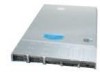
describes the main features of the server system. This chapter provides a illustrations of the product, a list of the server system features, and diagrams showing the location of important components and connections on the server system. TP02211 Figure 1. Intel® Integrated Server System SR1550AL - Intel SR1550ALSAS | User Guide - Page 24
Server Board Processor Memory Chipset Peripheral Interfaces I/O Controll Video LAN Expansion Capabilities Hard Drives Description • 1.700 inches (43.2mm) high • 16.930 inches (430.0mm) wide • 25.76 inches (654.4mm) deep • 37pounds (16.8 kg) - base chassis weight Intel® Server Board S5000PAL Support - Intel SR1550ALSAS | User Guide - Page 25
4-pin fan headers supporting two processor fans, and four system fans • Dedicated non-redundant power supply fan (one per module) • One front panel USB port • One internal USB header providing two USB ports Intel® System Management Software Intel® Server System SR1550AL/SR1550ALSAS User's Guide 5 - Intel SR1550ALSAS | User Guide - Page 26
Supply Air Duct M. Mid-plane Board (Active Shown) F. Power Supply Filler (Second Power Supply N. Mini Control Panel Bay if Installed) G. Power Supply Module O. Rack Handle H. Server Board P. Hard Drive Bays Figure 2. ChassisComponents 6 Intel® Server System SR1550AL/SR1550ALSAS User's Guide - Intel SR1550ALSAS | User Guide - Page 27
Drive Connector (Power + IO) X. Main Power Connector AA. Dual Port USB 2.0 Header DD. SATA Port 0 GG. SATA Port 3 JJ. SATA SW RAID 5 Activation Key Connector MM. Chassis Intrusion Switch Header OO. Intel® Local Control Panel Header PP. Serial A Header Intel® Server System SR1550AL/SR1550ALSAS - Intel SR1550ALSAS | User Guide - Page 28
BIOS in the lower bank will be selected on the next reset. These pins should be jumpered on 2-3 for normal operation. Figure 4. BIOS Select Jumper 8 Intel® Server System SR1550AL/SR1550ALSAS User's Guide - Intel SR1550ALSAS | User Guide - Page 29
Force Update Mode If pins 2-3 are jumpered, BMC Force Update Mode is enabled. These pins should be jumpered on 1-2 for normal operation. Figure 5. Recovery Jumpers Intel® Server System SR1550AL/SR1550ALSAS User's Guide 9 - Intel SR1550ALSAS | User Guide - Page 30
Fault H. DIMM C1 Fault I. DIMM C2 Fault J. DIMM D1 Fault K. DIMM D2 Fault L L. CPU 1 Fault M M. CPU 2 Fault N. 5V Standby CPU 2 CPU 1 Socket Socket Figure 6. Light Guided Diagnostic LEDs AF000644 10 Intel® Server System SR1550AL/SR1550ALSAS User's Guide - Intel SR1550ALSAS | User Guide - Page 31
RJ45 Serial B Connector B. Low Profile PCI Express* Add-in Card Slot D. Power Supply Module 1 F. Intel® Remote Management Module NIC (Optional) H. USB Port 5 J. Video L. NIC 1 (10/100/1000 Mb) N. Keyboard Figure 7. Back Panel Connectors Intel® Server System SR1550AL/SR1550ALSAS User's Guide 11 - Intel SR1550ALSAS | User Guide - Page 32
SR1550ALSAS provides SAS and SATA support. Both systems can be configured for RAID 0, 1, and 10. The Intel® Server System SR1550AL can be configured for SW RAID 5 by using the Intel® RAID Activation Key AXXRAKSW5 accessory. For information on configuring RAID, see the RAID software user's guide - Intel SR1550ALSAS | User Guide - Page 33
D 7654 E I H 3 12 0 F G TP02269 A. Fan 2 Power B. Fan 1 Power C. Thumbscrew D. Bridge Board Connector E. Mid-plane Power F. Fan 6 Power G. HBA I2C Connector H. Fan 4 Power I. Fan 3 Power Figure 8. Passive SATA Mid-Plane Components Intel® Server System SR1550AL/SR1550ALSAS User's Guide 13 - Intel SR1550ALSAS | User Guide - Page 34
Key Connector D. Bridge Board Connector E. Fan 6 Power F. Mini-DIMM Connector G. RAID Battery Backup Unit Connector H. Mid-plane Power I. Thumbscrew J. Fan 4 Power K. Fan 3 Power Figure 9. Active SAS/SATA Mid-Plane Components . 14 Intel® Server System SR1550AL/SR1550ALSAS User's Guide - Intel SR1550ALSAS | User Guide - Page 35
. Puts the system in an ACPI sleep state. Puts the server in a halt-state for diagnostic purposes Turns on/off the system identification LED. Allows you to attach a USB component to the front of the system. Figure 10. Mini Control Panel Intel® Server System SR1550AL/SR1550ALSAS User's Guide 15 - Intel SR1550ALSAS | User Guide - Page 36
is the Intel® Local Control Panel. For instructions on installing the standard control panel, see "Replacing the Control Panel". AB C D E F G H I L KJ TP02213 Callout A. B. C. D. E. F. G. H. I. Feature NIC 2 Activity LED NIC 1 Activity LED Power/Sleep Button Power/Sleep LED Hard Disk Drive - Intel SR1550ALSAS | User Guide - Page 37
Intel® Local Control Panel. The Intel® Local Control Panel is one of two required control options that can be selected. The other option is the standard control panel. For instructions light indicates system identification is not activated. Intel® Server System SR1550AL/SR1550ALSAS User's Guide 17 - Intel SR1550ALSAS | User Guide - Page 38
through the server chassis. Two bezels are available. One fits a system that has the standard control panel installed. The other is used for a chassis with the other Intel® Local Control Panel. Each bezel provides a lock to secure the hard drive and optical drive area. For instructions on installing - Intel SR1550ALSAS | User Guide - Page 39
can support up to six 2.5 inch hard drives. For instructions on installing hard drives, see "Installing and Removing a Hot-swap Hard Drive". Note: Drives can consume up to 17 watts of power each. Drives must be specified to run at a maximum ambient temperature of 45C. Note: The Intel® Server System - Intel SR1550ALSAS | User Guide - Page 40
only when system power is turned off. Drives in the optical drive carrier are NOT hot swappable. For installation instructions on installing an optical drive, see "Installing or Removing a Slimline Optical Drive or Internal USB Floppy". To use one of the drives provided by Intel, use the following - Intel SR1550ALSAS | User Guide - Page 41
3 Hardware Installations and Upgrades Before You Begin Before working with your server product, pay close attention to the "Safety Information" at the beginning of this manual. Tools and Supplies Needed • Phillips* (cross head) screwdriver (#1 bit and #2 bit) • Needle nosed pliers • Antistatic wrist - Intel SR1550ALSAS | User Guide - Page 42
at least one screw. If possible, attach at two places. 21. In the same manner, attach the other rail assembly to the other side. 22 Intel® Server System SR1550AL/SR1550ALSAS User's Guide - Intel SR1550ALSAS | User Guide - Page 43
server chassis) with the outer rail assemblies (attached to the rack). 9. Engage the matching rails and slide the server chassis into the rack until the two safety stops lock into position. 10. Depress the two safety locks (one on each side). Intel® Server System SR1550AL/SR1550ALSAS User's Guide - Intel SR1550ALSAS | User Guide - Page 44
right. If you are installing a bezel on your server system, make sure you position it as shown. TP02220 Figure 14. Front Bezel Supporting the Standard Control Panel TP02221 Figure 15. Front Bezel Supporting the Intel® Local Control Panel 24 Intel® Server System SR1550AL/SR1550ALSAS User's Guide - Intel SR1550ALSAS | User Guide - Page 45
below if your system includes a front bezel. 1. Unlock the bezel (if locked). 2. Disconnect any cables attached to the control panel. 3. Pull the bezel from the server system. Figure 17. Removing the Front Bezel TP02224 Intel® Server System SR1550AL/SR1550ALSAS User's Guide 25 - Intel SR1550ALSAS | User Guide - Page 46
of this book. See ""Safety Information". 2. Turn off all peripheral devices connected to the server. Turn off the server. 3. Disconnect the AC power cord. 4. Remove the security screw if it is installed. See letter "A" in the figure below. 26 Intel® Server System SR1550AL/SR1550ALSAS User's Guide - Intel SR1550ALSAS | User Guide - Page 47
into place (see letter "A"). 3. (Optional) Insert the security screw at the center of the top cover (see letter "B"). 4. Reconnect all peripheral devices and the AC power cord. A B TP02219 Figure 20. Installing the Server System Cover Intel® Server System SR1550AL/SR1550ALSAS User's Guide 27 - Intel SR1550ALSAS | User Guide - Page 48
the AC power cable. 3. Remove the server system cover. For instructions, see "Removing the Chassis Cover". 4. Lift the processor air duct from its location over the two processor sockets. TP02225 Figure 21. Removing the Processor Air Duct 28 Intel® Server System SR1550AL/SR1550ALSAS User's Guide - Intel SR1550ALSAS | User Guide - Page 49
under the air duct. 7. Install the server system cover. For instructions, see "Installing the Server System Cover". 8. Plug all peripheral devices and the AC power cable into the server. TP02226 Figure 23. Installing the Processor Air Duct Intel® Server System SR1550AL/SR1550ALSAS User's Guide 29 - Intel SR1550ALSAS | User Guide - Page 50
peripheral devices connected to the server. Turn off the server. 3. Disconnect the AC power cord from the server. 4. Remove the server's cover. For instructions, see "Removing the Chassis D A C B TP02072 Figure 24. Installing the Memory 30 Intel® Server System SR1550AL/SR1550ALSAS User's Guide - Intel SR1550ALSAS | User Guide - Page 51
: (1) Touch the metal chassis before touching the processor or server board. Keep part of your body in contact with the metal chassis to dissipate the static charge while handling the processor. (2) Avoid moving around unnecessarily. Intel® Server System SR1550AL/SR1550ALSAS User's Guide 31 - Intel SR1550ALSAS | User Guide - Page 52
). A B TP02075 Figure 26. Installing the Processor Note: Do not touch the socket pins; they are very sensitive and easily damaged. 7. Line up the alignment marks on the processor and the socket, and insert the processor into the socket. 32 Intel® Server System SR1550AL/SR1550ALSAS User's Guide - Intel SR1550ALSAS | User Guide - Page 53
cover (see Figure 27). Note: Retain the protective socket cover for use when removing a processor that will not be replaced. A B TP02076 Figure 27. Removing the Socket Cover 9. tightened. 3 2 1 4 TP02328 Figure 28. Installing the Heat Sink Intel® Server System SR1550AL/SR1550ALSAS User's Guide 33 - Intel SR1550ALSAS | User Guide - Page 54
cooling. To avoid possible damage to your server system, do not use older style drive carriers. Note: The server system does not support all hard drives. See "Server System References" for an Internet link to a list of supported hardware. 34 Intel® Server System SR1550AL/SR1550ALSAS User's Guide - Intel SR1550ALSAS | User Guide - Page 55
end of the drive so that it is facing the rear of the drive carrier. 7. Align the holes in the drive to the holes in the drive carrier and attach it to the carrier with the screws that were attached to the plastic retention device. Intel® Server System SR1550AL/SR1550ALSAS User's Guide 35 - Intel SR1550ALSAS | User Guide - Page 56
system cover. For instructions, see "Installing the Server System Cover". 11. (Optional) Install the front bezel. For instructions, see "Installing the Front Bezel". 12. Plug all peripheral devices and the AC power cable into the server. 36 Intel® Server System SR1550AL/SR1550ALSAS User's Guide - Intel SR1550ALSAS | User Guide - Page 57
: For proper airflow, the hard drive carrier must be replaced in the server system, even if no hard drive is installed in it. 8. When the black lever begins to close by itself, push on it to lock the drive carrier into place. 9. Install the server system cover. For instructions, see "Installing the - Intel SR1550ALSAS | User Guide - Page 58
. 8. Verify that the blue release lever on the tray locks into place. 9. (Optional) For installing the optional USB floppy drive, note the location of the backplane USB connector and refer to the documentation that came with the device. 38 Intel® Server System SR1550AL/SR1550ALSAS User's Guide - Intel SR1550ALSAS | User Guide - Page 59
cover. For instructions, see "Removing the Chassis Cover". 5. Press the blue release lever (see letter "A") to unlock the optical drive tray and remove the slimline optical drive tray assembly from the server system as shown in Figure 34. Intel® Server System SR1550AL/SR1550ALSAS User's Guide 39 - Intel SR1550ALSAS | User Guide - Page 60
devices and the AC power cable. 3. Remove the server system cover. For instructions, see "Removing the Chassis Cover". 4. Remove the processor air duct by lifting straight up. 5. Disconnect any cables attached to any add-in cards. 40 Intel® Server System SR1550AL/SR1550ALSAS User's Guide - Intel SR1550ALSAS | User Guide - Page 61
assembly. 7. Lift riser assembly straight up. TP02236 Figure 35. Removing PCI Riser Assembly from the Server System 8. If you need to add or replace a PCI add-in card, see "Installing and at the back of the server system (see letter "B"). Intel® Server System SR1550AL/SR1550ALSAS User's Guide 41 - Intel SR1550ALSAS | User Guide - Page 62
air duct. For instructions, see "Installing the Processor Air Duct". 6. Install the server system cover. For instructions, see "Installing the Server System Cover". 7. Plug all peripheral devices and the AC power cable into the server. 42 Intel® Server System SR1550AL/SR1550ALSAS User's Guide - Intel SR1550ALSAS | User Guide - Page 63
power cable. 3. Remove the server system cover. For instructions, see "Removing the Chassis Cover". 4. Remove the processor air duct. For instructions, see "Removing the Processor from the server system (see letter "C" in the figure below). Intel® Server System SR1550AL/SR1550ALSAS User's Guide 43 - Intel SR1550ALSAS | User Guide - Page 64
air duct. For instructions, see "Installing the Processor Air Duct". 15. Install the server system cover. For instructions, see "Installing the Server System Cover". 16. Plug all peripheral devices and the AC power cable into the server. 44 Intel® Server System SR1550AL/SR1550ALSAS User's Guide - Intel SR1550ALSAS | User Guide - Page 65
for information and add-in card requirements. 15. Re-install the processor air duct. For instructions, see "Installing the Processor Air Duct". 16. Install the server system cover. For instructions, see "Installing the Server System Cover". Intel® Server System SR1550AL/SR1550ALSAS User's Guide 45 - Intel SR1550ALSAS | User Guide - Page 66
both retention clips. Note: Make sure that all empty add-in card slots have filler panels installed. 10. Install the PCI riser assembly into the server system. For instructions, see "Installing the PCI Riser Assembly". 46 Intel® Server System SR1550AL/SR1550ALSAS User's Guide - Intel SR1550ALSAS | User Guide - Page 67
, see "Installing the PCI Riser Assembly". 10. Install the processor air duct. For instructions, see "Installing the Processor Air Duct". 11. Install the server system cover. For instructions, see "Installing the Server System Cover". Intel® Server System SR1550AL/SR1550ALSAS User's Guide 47 - Intel SR1550ALSAS | User Guide - Page 68
Module(s) to the Server Board 7. Install the PCI riser assembly into the server system. For instructions, see "Installing the PCI Riser Assembly". 8. Install the processor air duct. For instructions, see "Installing the Processor Air Duct". 48 Intel® Server System SR1550AL/SR1550ALSAS User's Guide - Intel SR1550ALSAS | User Guide - Page 69
air duct. For instructions, see "Installing the Processor Air Duct". 10. Install the server system cover. For instructions, see "Installing the Server System Cover". 11. Plug all peripheral devices and the AC power cable(s) into the server. Intel® Server System SR1550AL/SR1550ALSAS User's Guide 49 - Intel SR1550ALSAS | User Guide - Page 70
. 9. Attach the Intel® RMM board to the server board connector and snap the standoff into the matching hole on the server board. E B D F C A AF000747 Figure 43. Installing the Intel® RMM and the Intel® RMM NIC Module to the Server System 50 Intel® Server System SR1550AL/SR1550ALSAS User's Guide - Intel SR1550ALSAS | User Guide - Page 71
air duct. For instructions, see "Installing the Processor Air Duct". 12. Install the server system cover. For instructions, see "Installing the Server System Cover". 13. Plug all peripheral devices and the AC power cable into the server. Removing the Intel® RMM and Intel® RMM NIC 1. Observe - Intel SR1550ALSAS | User Guide - Page 72
processor air duct. For instructions, see "Installing the Processor Air Duct". 11. Install the server system cover. For instructions, see "Installing the Server System Cover". 12. Plug all peripheral devices and the AC power cable into the server Intel® Server System SR1550AL/SR1550ALSAS User's Guide - Intel SR1550ALSAS | User Guide - Page 73
below (see letter "B"). 8. Slide the mid-plane board forward (see letter "C") and insert the mid-plane into the backplane connector. 9. Tighten the thumbscrew (see letter "D"). Intel® Server System SR1550AL/SR1550ALSAS User's Guide 53 - Intel SR1550ALSAS | User Guide - Page 74
. 14. Install the bridge board and connect to the mid-plane board. 15. Install the server system cover. For instructions, see "Installing the Server System Cover". 16. Plug all peripheral devices and the AC power cable into the server. 54 Intel® Server System SR1550AL/SR1550ALSAS User's Guide - Intel SR1550ALSAS | User Guide - Page 75
Figure 47. Installing the RAID Activation Key and the RAID Mini DIMM 7. Install the server system cover. For instructions, see "Installing the Server System Cover". 8. Plug all peripheral devices and the AC power cable into the server. Intel® Server System SR1550AL/SR1550ALSAS User's Guide 55 - Intel SR1550ALSAS | User Guide - Page 76
Removing the Intel® Integrated RAID Activation Key and the RAID Mini DIMM 7. Install the server system cover. For instructions, see "Installing the Server System Cover". 8. Plug all peripheral devices and the AC power cable into the server. 56 Intel® Server System SR1550AL/SR1550ALSAS User's Guide - Intel SR1550ALSAS | User Guide - Page 77
RAID Battery Backup Unit TP02257 8. Install the power distribution board cover. For instructions, see "Replacing the Power Distribution Module". 9. Install the server system cover. For instructions, see "Installing the Server System Cover". Intel® Server System SR1550AL/SR1550ALSAS User's Guide - Intel SR1550ALSAS | User Guide - Page 78
cover. For instructions, see "Replacing the Power Distribution Module". 8. Install the server system cover. For instructions, see "Installing the Server System Cover". 9. Plug all peripheral devices and the AC power cable into the server. 58 Intel® Server System SR1550AL/SR1550ALSAS User's Guide - Intel SR1550ALSAS | User Guide - Page 79
peripheral devices and the AC power cable. 3. Remove the server system cover. For instructions, see "Removing the Chassis Cover". 4. Remove the processor air duct. For instructions, see "Removing the Processor Air Duct". 5. Remove the PCI riser assembly. For instructions, see "Removing the PCI Riser - Intel SR1550ALSAS | User Guide - Page 80
the fan pack. For instructions, see "Removing the Fan Pack". 9. Disconnect power from the server board. 10. Remove the six screws from the server board (see letter "A") and lift the server board from the server system (see letter "B"). 60 Intel® Server System SR1550AL/SR1550ALSAS User's Guide - Intel SR1550ALSAS | User Guide - Page 81
air duct. For instructions, see "Installing the Processor Air Duct". 14. Install the server system cover. For instructions, see "Installing the Server System Cover". 15. Plug all peripheral devices and the AC power cable into the server. Intel® Server System SR1550AL/SR1550ALSAS User's Guide 61 - Intel SR1550ALSAS | User Guide - Page 82
power. When the battery starts to weaken, it loses voltage, and the server settings stored in CMOS RAM in the RTC (for example, the date and time) may be wrong. Contact your customer service käytetty paristo valmistajan ohjeiden mukaisesti. 62 Intel® Server System SR1550AL/SR1550ALSAS User's Guide - Intel SR1550ALSAS | User Guide - Page 83
server. Turn off the server. 3. Disconnect the AC power cord from the server. 4. Remove the server's cover and locate the battery. See the documentation that came with your server chassis for instructions on removing the server to the RTC. Intel® Server System SR1550AL/SR1550ALSAS User's Guide 63 - Intel SR1550ALSAS | User Guide - Page 84
Figure 54. Removing Power Supply Filler Panel from the Server System 5. If a power supply is installed, release the latch (see letter "A") and remove the power supply by pulling on the handle (see letter "B") as shown in the figure below. 64 Intel® Server System SR1550AL/SR1550ALSAS User's Guide - Intel SR1550ALSAS | User Guide - Page 85
no power supply is to be installed, insert a power supply filler panel. 8. Install the server system cover. For instructions, see "Installing the Server System Cover". 9. Plug all peripheral devices and the AC power cable into the server. Intel® Server System SR1550AL/SR1550ALSAS User's Guide 65 - Intel SR1550ALSAS | User Guide - Page 86
board to the right and lifting. 9. Install a new power distribution board by lining up the standoffs to the holes in the power distribution board and sliding the board to the left. 10. Reconnect the power connections to the system boards. 66 Intel® Server System SR1550AL/SR1550ALSAS User's Guide - Intel SR1550ALSAS | User Guide - Page 87
/supplies. For instructions, see "Replacing or Adding a Power Supply". 13. Install the server system cover. For instructions, see "Installing the Server System Cover". 14. Plug all peripheral devices and the AC power cable into the server. Intel® Server System SR1550AL/SR1550ALSAS User's Guide - Intel SR1550ALSAS | User Guide - Page 88
the filler panel or two right drive carriers. 7. Slide the mini control panel out through the front of the server system (see letter "B" in the figure below). A B TP02245 Figure 59. Removing Mini Control Panel Module from the Server System 68 Intel® Server System SR1550AL/SR1550ALSAS User's Guide - Intel SR1550ALSAS | User Guide - Page 89
server system cover. For instructions, see "Installing the Server System Cover". 12. (Optional) Install the front bezel. For instructions, see "Installing the Front Bezel". 13. Plug all peripheral devices and the AC power cable into the server. Intel® Server System SR1550AL/SR1550ALSAS User's Guide - Intel SR1550ALSAS | User Guide - Page 90
, follow the instructions below. Note: If you reinstall the mini control panel, your system is now capable of supporting up to eight 2.5" hard drives. Caution: The control panel is NOT hot swappable. Before removing or replacing the control panel, you must first take the server out of service, turn - Intel SR1550ALSAS | User Guide - Page 91
drive carriers. 10. Install the server system cover. For instructions, see "Installing the Server System Cover". 11. (Optional) Install the front bezel. For instructions, see "Installing the Front Bezel". 12. Plug all peripheral devices and the AC power cable into the server. Intel® Server System - Intel SR1550ALSAS | User Guide - Page 92
the power supply cannot be replaced separately. If one of the fans in the power supply fails, the power supply must be replaced. The system fans at the front of the Intel® Server System SR1550AL on the fan is at the right and pointing down. 72 Intel® Server System SR1550AL/SR1550ALSAS User's Guide - Intel SR1550ALSAS | User Guide - Page 93
For instructions, see "Removing the Processor Air Duct". 5. Remove the power distribution board cover. For instructions, see "Replacing the Power Distribution Module". 6. Disconnect the IDE cable from the backplane. 7. Remove the bridge board. Intel® Server System SR1550AL/SR1550ALSAS User's Guide - Intel SR1550ALSAS | User Guide - Page 94
8. Disconnect the fan power cables from the mid-plane board as shown in the figure below (see letter "A"). 9. Press latch (see letter fan pack as shown in the figure below (see letter "D"). C B D A Figure 67. Removing the Fan Pack AF001497 74 Intel® Server System SR1550AL/SR1550ALSAS User's Guide - Intel SR1550ALSAS | User Guide - Page 95
air duct. For instructions, see "Installing the Processor Air Duct". 7. Install the server system cover. For instructions, see "Installing the Server System Cover". 8. Plug all peripheral devices and the AC power cable into the server. Intel® Server System SR1550AL/SR1550ALSAS User's Guide 75 - Intel SR1550ALSAS | User Guide - Page 96
AC power cable into the server. Removing the Rack Handles 1. Observe the safety and ESD precautions at the beginning of this book. See "Safety Information". 2. Power down the server and unplug all peripheral devices and the AC power cable. 76 Intel® Server System SR1550AL/SR1550ALSAS User's Guide - Intel SR1550ALSAS | User Guide - Page 97
shown in the figure below. AF000378 Figure 70. Removing the Rack Handle 6. Install the server system cover. For instructions, see "Installing the Server System Cover". 7. Plug all peripheral devices and the AC power cable into the server. Intel® Server System SR1550AL/SR1550ALSAS User's Guide 77 - Intel SR1550ALSAS | User Guide - Page 98
78 Intel® Server System SR1550AL/SR1550ALSAS User's Guide - Intel SR1550ALSAS | User Guide - Page 99
Intel® 5000 Series Chipsets Server Board Family Datasheet where you will find details about specific BIOS setup screens. Starting Setup You can enter and start BIOS Setup under several conditions: • When you turn on the server, after POST completes the memory the CMOS memory. For instructions on - Intel SR1550ALSAS | User Guide - Page 100
if the key is pressed, the user is returned to where they were before was pressed without affecting any existing field values. 80 Intel® Server System SR1550AL/SR1550ALSAS User's Guide - Intel SR1550ALSAS | User Guide - Page 101
utility allows you to upgrade the BIOS in flash memory. The code and data in the upgrade file include to be followed to return the system to service. See "Server System References" for a link to necessary server at the end of the procedure. Intel® Server System SR1550AL/SR1550ALSAS User's Guide 81 - Intel SR1550ALSAS | User Guide - Page 102
Obtaining the Upgrade Download the BIOS image file to a temporary folder on your hard drive. See "Server System References" for a link to the update software. Note: Review the instructions and release notes that are provided in the readme file distributed with the BIOS image file before attempting a - Intel SR1550ALSAS | User Guide - Page 103
RAM. 1. Power down the system and disconnect the AC power. 2. Open the server. 3. Move the jumper from the normal operation position, CMOS Clear by BMC, at pins 1 and 2 to the CMOS Clear Force Erase position, covering pins 2 and 3. Intel® Server System SR1550AL/SR1550ALSAS User's Guide 83 - Intel SR1550ALSAS | User Guide - Page 104
Return the CMOS Clear jumper to the CMOS Clear by BMC location, covering pins 1 and 2. 6. Close the server chassis. 7. Reconnect the AC power and power up the system. 8. The CMOS is now cleared and can be reset by going into the BIOS setup. 84 Intel® Server System SR1550AL/SR1550ALSAS User's Guide - Intel SR1550ALSAS | User Guide - Page 105
) D Power Supply E Bridge Board F Mid-plane Board (active shown) G Power Distribution Board H Backplane Board I Power to Mid-plane Board J Power to Backplane Board K Power to Server Board (CPU) L Power to Server Board (Main) M Power to Server Board (Aux.) N Fan Power Cables O RAID Battery Power to - Intel SR1550ALSAS | User Guide - Page 106
0 1 A 2 3 4 5 4567 B 0 1 2 3 A Figure 74. SATA Cable Installation TP02249 750W Single Power Supply Input Voltages • 100-127V at 50/60 Hz; 12 A max. • 200-240V at 50/60 Hz; 6 A max. 86 Intel® Server System SR1550AL/SR1550ALSAS User's Guide - Intel SR1550ALSAS | User Guide - Page 107
A Maximum Current Warning: Do not exceed a combined power output of 90 Watts for the +5 V and +3.3 V outputs. Exceeding a combined 90 Watts will overload the power subsystem and may cause the power supplies to overheat and malfunction. Intel® Server System SR1550AL/SR1550ALSAS User's Guide 87 - Intel SR1550ALSAS | User Guide - Page 108
g, 11 msec, 1/2 sine Operational after an 18" free fall. 7 Bels in sound power for a typical office ambient temperature (65-75 °F). Your selection of peripherals may change the noise level. Tested to 15 kilovolts (kV); no component damage. 88 Intel® Server System SR1550AL/SR1550ALSAS User's Guide - Intel SR1550ALSAS | User Guide - Page 109
" for a link to the software updates. In addition to the server firmware and files, also update any drivers used for components you have installed in your system, such as video drivers, network drivers, and SATA drivers. Intel provides a package called the "Platform Confidence Test" that may help - Intel SR1550ALSAS | User Guide - Page 110
Are all integrated components from the tested components lists? Check the tested memory, and chassis lists, as well as the supported hardware and operating system list. See "Server System References" for links to the tested component lists. 90 Intel® Server System SR1550AL/SR1550ALSAS User's Guide - Intel SR1550ALSAS | User Guide - Page 111
to identifying a hardware problem and locating its supplied with your video display monitor). 4. If the operating system normally loads from the hard disk drive, make sure there is no CD-ROM / DVD disk in the optical drive. 5. If the power Intel® Server System SR1550AL/SR1550ALSAS User's Guide 91 - Intel SR1550ALSAS | User Guide - Page 112
to the system requirements. • Remove the processor(s) and re-seat them. • Make sure the chassis standoffs are installed only below mounting holes. Misplaced standoffs can contact the pins on the bottom of the server board and cause a short. 92 Intel® Server System SR1550AL/SR1550ALSAS User's Guide - Intel SR1550ALSAS | User Guide - Page 113
memory DIMMs have been populated according to the system requirements. • Remove the memory DIMMs and re-seat them. • Make sure the processor(s) comply with the system requirements. • Make sure the processor power cables properly installed? Intel® Server System SR1550AL/SR1550ALSAS User's Guide 93 - Intel SR1550ALSAS | User Guide - Page 114
Drive Activity Light Does Not Light Check the following: • Are the CD-ROM/DVD-ROM drive's power and signal cables properly installed? • Are all relevant switches and jumpers on the drive set correctly? • Is the drive properly configured? 94 Intel® Server System SR1550AL/SR1550ALSAS User's Guide - Intel SR1550ALSAS | User Guide - Page 115
supports shared interrupts. Make sure your operating system supports shared interrupts. • Try reseating the add-in adapter. The add-in adapter stopped working without apparent cause • Reseat the adater. • Put the adapter in a different slot. Intel® Server System SR1550AL/SR1550ALSAS User's Guide - Intel SR1550ALSAS | User Guide - Page 116
device drivers installed. If the problems persist, contact the software vendor's customer service representative. Problems with Application Software that Ran Correctly Earlier Problems software. Make sure all necessary files are installed. 96 Intel® Server System SR1550AL/SR1550ALSAS User's Guide - Intel SR1550ALSAS | User Guide - Page 117
the current drivers and chipset files. Hard Drive(s) are not Recognized Check the following: • Make sure the drive is not disabled in BIOS Setup. • Make sure the drive is connected correctly and that is plugged into the power supply. • Make sure the drive is compatible. See "Server System References - Intel SR1550ALSAS | User Guide - Page 118
LED Information The Intel® Server Board S5000PAL includes LEDs that can aid in troubleshooting your system. A table of these LEDs with a description of their use is listed below. Table 8. LED Information LED Name Power ID System Status Function Location Indicates system power Front control is - Intel SR1550ALSAS | User Guide - Page 119
is empty. Reseat or replace the failed processor. In a two-processor system, make sure the processors are identical. Front-side bus select configuration error. DC power unexpectedly lost. Chipset control failure. Power control failure. Intel® Server System SR1550AL/SR1550ALSAS User's Guide 99 - Intel SR1550ALSAS | User Guide - Page 120
100 Intel® Server System SR1550AL/SR1550ALSAS User's Guide - Intel SR1550ALSAS | User Guide - Page 121
at http:// support.intel.com/support/motherboards/server/chassis/SR1550/. For the fastest service, please submit your form via the Internet. Date Submitted Company Name Contact Name Email Address Intel Server Product Priority (Critical, Hot, High, Low Brief Problem Description. Provide - Intel SR1550ALSAS | User Guide - Page 122
D2 MB and Vendor / part number Operating System Information Operating System Version Service Pack Add-in Card, Peripheral, Video, NIC Check each box below PCI Slot Description Driver Revision IRQ I/O Base FW Address Revision 102 Intel® Server System SR1550AL/SR1550ALSAS User's Guide - Intel SR1550ALSAS | User Guide - Page 123
NIC1 On-Board NIC2 Description Hard Drive Information Drive Type (SCSI, SATA, etc) Make/Model Driver Revision IRQ I/O Base FW Address Revision Hot-swap or Fixed IRQ FW Revision Management Information On-Board Platform Instrumentation only Intel® Remote Management Module Control Panel - Intel SR1550ALSAS | User Guide - Page 124
Description In the space below, provide a complete description of the steps used to reproduce the problem or a complete description of where the problem can be found. Please also include any details on troubleshooting already done 104 Intel® Server System SR1550AL/SR1550ALSAS User's Guide - Intel SR1550ALSAS | User Guide - Page 125
routine is started, BIOS will display the given POST code to the POST Code Diagnostic LEDs found on the back edge of the server board. To assist in troubleshooting a system hang during the POST process, the Diagnostic LEDs can be used to identify the last POST process to be executed. Each POST - Intel SR1550ALSAS | User Guide - Page 126
of memory OFF Programming timing parameters in the memory controller G Configuring memory parameters in the memory controller OFF Optimizing memory controller settings G Initializing memory, such as ECC init OFF Testing memory 106 Intel® Server System SR1550AL/SR1550ALSAS User's Guide - Intel SR1550ALSAS | User Guide - Page 127
(VGA) Resetting the console controller Disabling the console controller Enabling the console controller Resetting the keyboard Disabling the keyboard Detecting the presence of the keyboard Intel® Server System SR1550AL/SR1550ALSAS User's Guide 107 - Intel SR1550ALSAS | User Guide - Page 128
OFF R Clearing keyboard input buffer R G OFF A Instructing keyboard controller to run Self Test (PS2 only) presence of a fixed media device (IDE hard drive detection, etc.) R OFF A A Enabling OFF A Trying boot device selection 108 Intel® Server System SR1550AL/SR1550ALSAS User's Guide - Intel SR1550ALSAS | User Guide - Page 129
Sleep state A R R R Operating system has requested EFI to close boot services (ExitBootServices ( ) has been called) A R R A Operating system has switched to virtual address mode (SetVirtualAddressMap ( ) has been called) Intel® Server System SR1550AL/SR1550ALSAS User's Guide 109 - Intel SR1550ALSAS | User Guide - Page 130
initiated by software (corrupt flash) OFF G R R Loading crisis recovery capsule OFF G R A Handing off control to the crisis recovery capsule G G A A Unable to complete crisis recovery. 110 Intel® Server System SR1550AL/SR1550ALSAS User's Guide - Intel SR1550ALSAS | User Guide - Page 131
Appendix E: Getting Help World Wide Web http://support.intel.com/support/motherboards/server/chassis/SR1550. Telephone All calls are billed per incident, levied in local currency at the applicable credit card exchange rate plus applicable taxes. (Intel reserves the right to change the pricing for - Intel SR1550ALSAS | User Guide - Page 132
8 621 33104691 (not toll-free) Hong Kong 852 2 844 4456 India........... 0006517 2 68303634 (manual toll-free. You need an IDD-equipped telephone) Indonesia ... 803 65 7249 Korea ......... 822 767 225 288. Once connected, dial 800 843 4481 112 Intel® Server System SR1550AL/SR1550ALSAS User's Guide - Intel SR1550ALSAS | User Guide - Page 133
0114 Peru 001 916 377 0114 Uruguay..... 001 916 377 0114 Venezuela... Contact AT&T USA at 0 800 2255 288. Once connected, dial 800 843 4481 Intel® Server System SR1550AL/SR1550ALSAS User's Guide 113 - Intel SR1550ALSAS | User Guide - Page 134
114 Intel® Server System SR1550AL/SR1550ALSAS User's Guide - Intel SR1550ALSAS | User Guide - Page 135
assembly instructions in this guide to the server system, power supply, and other modules have passed EMC testing using a server board server board. The final configuration of your end system product may require additional EMC compliance testing. For more information, please contact your local Intel - Intel SR1550ALSAS | User Guide - Page 136
License (Ukraine) • RRL MIC Notice No. 1997-41 (EMC) & 1997-42 (EMI) (Korea) • GB 9254 - CNCA Certification (China) • GB 17625 - (Harmonics) CNCA Certification (China) 116 Intel® Server System SR1550AL/SR1550ALSAS User's Guide - Intel SR1550ALSAS | User Guide - Page 137
China) • Ecology Declaration (International) Product Regulatory Compliance Markings This Intel® server system product is provided with the following regulatory marks. Table Europe FCC Marking (Class A) USA EMC Marking (Class A) Canada Intel® Server System SR1550AL/SR1550ALSAS User's Guide 117 - Intel SR1550ALSAS | User Guide - Page 138
two conditions: (1) this device may not cause harmful interference, and (2) this device must accept any interference received, including interference that may cause undesired operation. 118 Intel® Server System SR1550AL/SR1550ALSAS User's Guide - Intel SR1550ALSAS | User Guide - Page 139
EMC performance of this product, contact: Intel Corporation 5200 N.E. Elam Young Parkway Hillsboro, OR if not installed and used in accordance with the instructions, may cause harmful interference to radio communications. However, . Intel® Server System SR1550AL/SR1550ALSAS User's Guide 119 - Intel SR1550ALSAS | User Guide - Page 140
radio interference. Install and use the equipment according to the instruction manual. BSMI (Taiwan) The BSMI Certification Marking and EMC warning is from local Intel representative 3. Name of Certification Recipient: Intel Corporation 120 Intel® Server System SR1550AL/SR1550ALSAS User's Guide - Intel SR1550ALSAS | User Guide - Page 141
5. Manufacturer/Nation: Intel Corporation/Refer to country of accessory and TUV or VDE licensed. Maximum power rating of any one device is 19 watts. Total server configuration is not to exceed the maximum loading conditions of the power supply. Intel® Server System SR1550AL/SR1550ALSAS User's Guide - Intel SR1550ALSAS | User Guide - Page 142
Restriction of Hazardous Substances (RoHS) Compliance Intel has a system in place to restrict the use of banned substances in accordance with the or distributor of this product for information about product recycling and / or take-back. 122 Intel® Server System SR1550AL/SR1550ALSAS User's Guide - Intel SR1550ALSAS | User Guide - Page 143
Product by means of hardware and/or software; OR • REPLACE the Product with another Product; OR • REFUND the then-current value of the Product if Intel is unable to repair or replace the Product. If such Product is defective, transportation charges for the return of Product to buyer within the USA - Intel SR1550ALSAS | User Guide - Page 144
due to external causes, including accident, problems with electrical power, usage not in accordance with product instructions, misuse, neglect, alteration, repair, improper Limited Warranty, the English language version shall control. 124 Intel® Server System SR1550AL/SR1550ALSAS User's Guide - Intel SR1550ALSAS | User Guide - Page 145
for the product, please go to the following Web site to obtain instructions: http://support.intel.com/support/ motherboards/draform.htm • In Europe and in Asia Contact your original authorized distributor for warranty service. Any replacement Product is warranted under this written warranty and is - Intel SR1550ALSAS | User Guide - Page 146
126 Intel® Server System SR1550AL/SR1550ALSAS User's Guide - Intel SR1550ALSAS | User Guide - Page 147
Assembly Safety Instructions English The power supply in this product contains no user-serviceable parts. Refer servicing only to qualified personnel. Do not attempt to modify or use the supplied AC power cord if it is not the exact type required. A product with more than one power supply will have - Intel SR1550ALSAS | User Guide - Page 148
the equipment manufacturer. Dispose of used batteries according to manufacturer's instructions. The system is designed to operate in a typical office power supply cord(s), because they serve as the product's main power disconnect. 128 Intel® Server System SR1550AL/SR1550ALSAS User's Guide - Intel SR1550ALSAS | User Guide - Page 149
, um elektrostatische Ladungen (ESD) über blanke Metallstellen bei der Handhabung der Komponenten zu vermeiden. 6. Schalten Sie das System niemals ohne ordnungsgemäß montiertes Gehäuse ein. Intel® Server System SR1550AL/SR1550ALSAS User's Guide 129 - Intel SR1550ALSAS | User Guide - Page 150
. Die Batterie darf nur durch denselben oder einen entsprechenden, vom Hersteller empfohlenen Batterietyp ersetzt werden. Entsorgen Sie verbrauchte Batterien den Anweisungen des Herstellers entsprechend. 130 Intel® Server System SR1550AL/SR1550ALSAS User's Guide - Intel SR1550ALSAS | User Guide - Page 151
panneau avant n'éteint pas l'alimentation CA du système. Pour mettre le système hors tension, vous devez débrancher chaque câble d'alimentation de sa prise. Intel® Server System SR1550AL/SR1550ALSAS User's Guide 131 - Intel SR1550ALSAS | User Guide - Page 152
a été sous tension. Faites également attention aux broches aiguës des cartes et aux bords tranchants du capot. Nous vous recommandons l'usage de gants de protection. 132 Intel® Server System SR1550AL/SR1550ALSAS User's Guide - Intel SR1550ALSAS | User Guide - Page 153
type ou d'un type équivalent recommandé par le fabricant. Disposez des piles usées selon les instructions du fabricant. Le système a été conçu pour fonctionner dans un cadre de travail normal. ón de corriente alterna que tenga el producto Intel® Server System SR1550AL/SR1550ALSAS User's Guide 133 - Intel SR1550ALSAS | User Guide - Page 154
sistema y bloquéelo para impedir que pueda accederse al mismo sin autorización. 5. Conecte todos los cables externos y los cables de alimentación CA al sistema. 134 Intel® Server System SR1550AL/SR1550ALSAS User's Guide - Intel SR1550ALSAS | User Guide - Page 155
tierra correctamente instalada. • "Provisto de espacio suficiente como para acceder a los cables de alimentación, ya que éstos hacen de medio principal de desconexión del sistema. Intel® Server System SR1550AL/SR1550ALSAS User's Guide 135 - Intel SR1550ALSAS | User Guide - Page 156
lucchetto dal retro del sistema qualora ve ne fosse uno installato. 2. Togliere e mettere in un posto sicuro tutte le viti delle coperture. 3. Togliere le coperture. Intel® Server System SR1550AL/SR1550ALSAS User's Guide - Intel SR1550ALSAS | User Guide - Page 157
di una presa a muro correttamente installata. • "Dotata di spazio sufficiente ad accedere ai cavi di alimentazione, i quali rappresentano il mezzo principale di scollegamento del sistema. Intel® Server System SR1550AL/SR1550ALSAS User's Guide 137 - Intel SR1550ALSAS | User Guide - Page 158
138 Intel® Server System SR1550AL/SR1550ALSAS User's Guide - Intel SR1550ALSAS | User Guide - Page 159
product, the product documentation takes precedence. Your server should be integrated and serviced only by technically qualified persons. You must adhere to the guidelines in this guide and the assembly instructions in your server manuals to ensure and maintain compliance with existing product - Intel SR1550ALSAS | User Guide - Page 160
. • Provided with sufficient space to access the power supply cord(s), because they serve as the product's main power disconnect. Equipment Handling Practices Reduce the risk of for easier handling, remove any easily detachable components. 140 Intel® Server System SR1550AL/SR1550ALSAS User's Guide - Intel SR1550ALSAS | User Guide - Page 161
disconnect device to AC power. The socket outlet(s) must be near the equipment and readily accessible for disconnection. • The power supply cord(s) must be plugged into socket-outlet(s) that is /are provided with a suitable earth ground. Intel® Server System SR1550AL/SR1550ALSAS User's Guide 141 - Intel SR1550ALSAS | User Guide - Page 162
, and it must be labeled as controlling power to the entire unit, not just to the server(s). To avoid risk of potential electric shock, a proper safety ground must be implemented for the rack and each piece of equipment installed in it. 142 Intel® Server System SR1550AL/SR1550ALSAS User's Guide - Intel SR1550ALSAS | User Guide - Page 163
Caution: Carefully route cables as directed to minimize airflow blockage and cooling problems. For proper cooling and airflow, operate the system only with the or devices have are not user serviceable • Return to manufacturer for servicing Intel® Server System SR1550AL/SR1550ALSAS User's Guide 143 - Intel SR1550ALSAS | User Guide - Page 164
hin, der bei Nichtbeachtung der Sicherheitshinweise zu schweren oder tödlichen Verletzungen führen kann. Weist auf Verbrennungsgefahr an heißen Bauteilen bzw. Oberflächen hin. 144 Intel® Server System SR1550AL/SR1550ALSAS User's Guide - Intel SR1550ALSAS | User Guide - Page 165
Transportieren oder Anheben von Geräten. • Entfernen Sie alle Komponenten, die sich leicht abnehmen lassen, um das Gewicht zu reduzieren und die Handhabung zu erleichtern. Intel® Server System SR1550AL/SR1550ALSAS User's Guide 145 - Intel SR1550ALSAS | User Guide - Page 166
vom Stromnetz. Die Steckdose muß in der Nähe der Anlage angebracht und gut erreichbar sein. • Netzkabel müssen an eine ordnungsgemäß geerdete Steckdose angeschlossen sein. 146 Intel® Server System SR1550AL/SR1550ALSAS User's Guide - Intel SR1550ALSAS | User Guide - Page 167
Teile. Schicken Sie das Gerät für Wartungsarbeiten an den Hersteller zurück. • Schalten Sie den Server aus, und ziehen Sie alle Netzkabel ab, bevor Sie Komponenten ein- oder ausbauen, die nicht hot immer nur ein Gerät aus dem Rack heraus. Intel® Server System SR1550AL/SR1550ALSAS User's Guide 147 - Intel SR1550ALSAS | User Guide - Page 168
Platinen nach dem Auspacken aus der Schutzhülle oder nach dem Ausbau aus dem Server mit der Bauelementseite nach oben auf eine geerdete, statisch entladene Unterlage. Verwenden Sie dazu Werkzeuge oder Teile im Gehäuse vergessen haben. 148 Intel® Server System SR1550AL/SR1550ALSAS User's Guide - Intel SR1550ALSAS | User Guide - Page 169
uniquement par des techniciens qualifiés. Vous devez suivre les informations de ce guide et les instructions d'assemblage des manuels de serveur pour vérifier et maintenir la conformit et peuvent figurer sur le produit ou sur son emballage. Intel® Server System SR1550AL/SR1550ALSAS User's Guide 149 - Intel SR1550ALSAS | User Guide - Page 170
soleil et les radiateurs. • À l'écart des sources de vibration ou des chocs physiques. • Isolé des champs électromagnétiques importants produits par des appareils électriques. 150 Intel® Server System SR1550AL/SR1550ALSAS User's Guide - Intel SR1550ALSAS | User Guide - Page 171
ou de supprimer un composant non connectable à chaud. Les alimentations de certains serveurs Intel sont munies de doubles fusibles pôle/neutre: veuillez observer les précautions d'usage . L'intérieur de celui-ci est soumis à des Intel® Server System SR1550AL/SR1550ALSAS User's Guide 151 - Intel SR1550ALSAS | User Guide - Page 172
Les cordons d'alimentation doivent répondre aux critères suivants : - Le cordon d'alimentation doit supporter une intensité supérieure à celle indiquée sur le produit. - Le cordon d'alimentation communication qui sont connectés au système. 152 Intel® Server System SR1550AL/SR1550ALSAS User's Guide - Intel SR1550ALSAS | User Guide - Page 173
montage en rack Le rack doit être fixé à un support inamovible pour éviter qu'il ne bascule lors de l'extension quipement. Le rack doit être installé conformément aux instructions du fabricant. Installez les équipements dans le rack en Intel® Server System SR1550AL/SR1550ALSAS User's Guide 153 - Intel SR1550ALSAS | User Guide - Page 174
système. • Vérifiez que les câbles, les cartes d'extension et les autres composants sont correctement installés. • Fixez les panneaux au châssis en suivant les instructions du produit. 154 Intel® Server System SR1550AL/SR1550ALSAS User's Guide - Intel SR1550ALSAS | User Guide - Page 175
irse a las directrices de esta guía y a las instrucciones de montaje de los manuales del servidor para asegurar y mantener el cumplimiento con las certificaciones y homologaciones existentes de si no se tiene en cuenta la ADVERTENCIA. Intel® Server System SR1550AL/SR1550ALSAS User's Guide 155 - Intel SR1550ALSAS | User Guide - Page 176
conectada a tierra. • Provista de espacio suficiente para acceder a los cables de la fuente de alimentación ya que constituyen la desconexión principal de la alimentación. 156 Intel® Server System SR1550AL/SR1550ALSAS User's Guide - Intel SR1550ALSAS | User Guide - Page 177
conexión en funcionamiento. Algunas fuentes de alimentación de electricidad de los servidores de Intel utilizan el polo neutral del fuselaje. Para evitar riesgos de choques electricos use adquiera alguno cuyo uso esté aprobado en su país. Intel® Server System SR1550AL/SR1550ALSAS User's Guide 157 - Intel SR1550ALSAS | User Guide - Page 178
para repararla. • Apague el servidor y desconecte todos los cables de alimentación antes de agregar o reemplazar cualquier componente que no es de conexión en funcionamiento. 158 Intel® Server System SR1550AL/SR1550ALSAS User's Guide - Intel SR1550ALSAS | User Guide - Page 179
y otros componentes. Recomendamos que realice todos los procedimientos en una estación de trabajo protegida contra descargas electrostáticas. En caso de que no haya una Intel® Server System SR1550AL/SR1550ALSAS User's Guide 159 - Intel SR1550ALSAS | User Guide - Page 180
dentro del sistema. • Compruebe que los cables, tarjetas adicionales y otros componentes están instalados correctamente. • Sujete las cubiertas a la carcasa siguiendo las instrucciones del producto. 160 Intel® Server System SR1550AL/SR1550ALSAS User's Guide - Intel SR1550ALSAS | User Guide - Page 181
caja de ningún periférico o dispositivo láser • Los periféricos o dispositivos láser no pueden ser reparados por el usuario • Haga que el fabricante los repare Intel® Server System SR1550AL/SR1550ALSAS User's Guide 161 - Intel SR1550ALSAS | User Guide - Page 182
162 Intel® Server System SR1550AL/SR1550ALSAS User's Guide
-
 1
1 -
 2
2 -
 3
3 -
 4
4 -
 5
5 -
 6
6 -
 7
7 -
8
-
9
-
10
-
11
-
12
-
13
-
14
-
15
-
16
-
17
-
18
-
19
-
20
-
21
-
22
-
23
-
24
-
25
-
26
-
27
-
28
-
29
-
30
-
31
-
32
-
33
-
34
-
35
-
36
-
37
-
38
-
39
-
40
-
41
-
42
-
43
-
44
-
45
-
46
-
47
-
48
-
49
-
50
-
51
-
52
-
53
-
54
-
55
-
56
-
57
-
58
-
59
-
60
-
61
-
62
-
63
-
64
-
65
-
66
-
67
-
68
-
69
-
70
-
71
-
72
-
73
-
74
-
75
-
76
-
77
-
78
-
79
-
80
-
81
-
82
-
83
-
84
-
85
-
86
-
87
-
88
-
89
-
90
-
91
-
92
-
93
-
94
-
95
-
96
-
97
-
98
-
99
-
100
-
101
-
102
-
103
-
104
-
105
-
106
-
107
-
108
-
109
-
110
-
111
-
112
-
113
-
114
-
115
-
116
-
117
-
118
-
119
-
120
-
121
-
122
-
123
-
124
-
125
-
126
-
127
-
128
-
129
-
130
-
131
-
132
-
133
-
134
-
135
-
136
-
137
-
138
-
139
-
140
-
141
-
142
-
143
-
144
-
145
-
146
-
147
-
148
-
149
-
150
-
151
-
152
-
153
-
154
-
155
-
156
-
157
-
158
-
159
-
160
-
161
-
162
-
163
-
164
-
165
-
166
-
167
-
168
-
169
-
170
-
171
-
172
-
173
-
174
-
175
-
176
-
177
-
178
-
179
-
180
-
181
-
182
 |
 |

Intel
®
Server System SR1550AL/
SR1550ALSAS User’s Guide
A Guide for Technically Qualified Assemblers of Intel® Identified Subassemblies/
Products
Intel Order Number D31972-002