Intel SR1560SFHS Service Guide
Intel SR1560SFHS - Server System - 0 MB RAM Manual
 |
UPC - 735858197595
View all Intel SR1560SFHS manuals
Add to My Manuals
Save this manual to your list of manuals |
Intel SR1560SFHS manual content summary:
- Intel SR1560SFHS | Service Guide - Page 1
Intel® Server System SR1560SF Service Guide A Guide for Technically Qualified Assemblers of Intel® Identified Subassemblies/ Products Intel Order Number D92960-004 - Intel SR1560SFHS | Service Guide - Page 2
Xeon are trademarks or registered trademarks of Intel Corporation or its subsidiaries in the United States and other countries. * Other names and brands may be claimed as the property of others. Copyright © 2010, Intel Corporation. All Rights Reserved ii Intel® Server System SR1560SF Service Guide - Intel SR1560SFHS | Service Guide - Page 3
Intel® Server System SR1560SF Service Guide iii - Intel SR1560SFHS | Service Guide - Page 4
iv Intel® Server System SR1560SF Service Guide - Intel SR1560SFHS | Service Guide - Page 5
purchasing and using the Intel® Server System SR1560SF. This manual is written for system technicians who are responsible for troubleshooting, upgrading, and repairing this server system. This document provides reference information, feature information, and step by step instructions on how to add - Intel SR1560SFHS | Service Guide - Page 6
in the server system • Two SATA cables, in hardware box • Processor air duct, installed in the server system • Blue plastic air baffle, installed in the server system • Intel® Server Deployment Toolkit 2.0 CD • Intel® System Management Software CD vi Intel® Server System SR1560SF Service Guide - Intel SR1560SFHS | Service Guide - Page 7
hot-swap backplane kits must be ordered separately in order to make the system operational. The following kits are available for purchase. • Passive hot-swap backplane. Order code: ASR1500PASBP • Active hot-swap backplane. Order code: ASR1500SASBP Intel® Server System SR1560SF Service Guide vii - Intel SR1560SFHS | Service Guide - Page 8
viii Intel® Server System SR1560SF Service Guide - Intel SR1560SFHS | Service Guide - Page 9
in this document before performing any of the instructions. See also Intel Server Boards and Server Chassis Safety Information on the Intel® Server Deployment Toolkit 2.0 CD and/or at http://support.intel.com/support/motherboards/server/sb/cs-010770.htm. Wichtige Sicherheitshinweise Lesen Sie - Intel SR1560SFHS | Service Guide - Page 10
http://support.intel.com/support/motherboards/server/sb/CS-010770.htm 上的 Intel Server Boards and Server Chassis Safety Information(《Intel x Intel® Server System SR1560SF Service Guide - Intel SR1560SFHS | Service Guide - Page 11
the contacts inside the jumper, causing intermittent problems with the function controlled by that jumper. Take care to grip with, but not squeeze, the pliers or other tool you use to remove a jumper, or you may bend or break the pins on the board. Intel® Server System SR1560SF Service Guide xi - Intel SR1560SFHS | Service Guide - Page 12
xii Intel® Server System SR1560SF Service Guide - Intel SR1560SFHS | Service Guide - Page 13
...v About this Manual ...v Manual Organization ...v Product Contents ...vi Intel® Server System SR1560SF - Product Code SR1560SF Contents vi Intel® Server System SR1560SF - Product Code SR1560SFHS Contents vii Safety Information ...ix Important Safety Instructions ix Wichtige Sicherheitshinweise - Intel SR1560SFHS | Service Guide - Page 14
Board 45 Replacing the Fan Board (Fixed Drive System Only 46 Removing the Fan Board 46 Installing the Fan Board 47 Replacing the Server Board 47 Removing the Server Board 47 Installing the Server Board 49 Replacing the Backup Battery 50 xiv Intel® Server System SR1560SF Service Guide - Intel SR1560SFHS | Service Guide - Page 15
BIOS ...62 Clearing the CMOS ...62 Resetting the Password ...63 Appendix A: Technical Reference 65 600W Single Power Supply Input Voltages 65 System Environmental Specifications 65 Appendix B: Intel® Server 91 End-of-Life / Product Recycling 92 Intel® Server System SR1560SF Service Guide xv - Intel SR1560SFHS | Service Guide - Page 16
Intel® Chassis Subassembly Products 93 Appendix G: Installation/Assembly Safety Instructions 97 English ...97 Deutsch ...99 Français ...101 Español ...103 Chinese ...106 Italiano ...106 Appendix H: Safety Information 109 English ...109 Server 124 xvi Intel® Server System SR1560SF Service Guide - Intel SR1560SFHS | Service Guide - Page 17
cable de alimentación 127 Advertencias el acceso al sistema 128 Advertencias sobre el montaje en bastidor 129 Descarga electrostática (ESD 130 Otros riesgos ...130 Intel® Server System SR1560SF Service Guide xvii - Intel SR1560SFHS | Service Guide - Page 18
xviii Intel® Server System SR1560SF Service Guide - Intel SR1560SFHS | Service Guide - Page 19
Optical Drive Assembly from the Server System 37 Figure 39. Removing the Slimline Optical Drive from the Tray 38 Figure 40. Removing PCI Riser Assembly from the Server System 39 Figure 41. Installing PCI Riser Assembly into the Server System 39 Intel® Server System SR1560SF Service Guide xix - Intel SR1560SFHS | Service Guide - Page 20
. Removing the Rack Handle 57 Figure 67. Clear CMOS Jumper 62 Figure 68. Password Reset Jumper 63 Figure 69. Diagnostic LED Placement Diagram 71 xx Intel® Server System SR1560SF Service Guide - Intel SR1560SFHS | Service Guide - Page 21
Environmental Specifications 65 Table 6. POST Progress Code LED Example 71 Table 7. Diagnostic LED POST Code Decoder 72 Table 8. Product Regulatory Compliance Markings 82 Table 9. Product Ecology Compliance Markings 88 Table 10. Other Markings ...90 Intel® Server System SR1560SF Service Guide - Intel SR1560SFHS | Service Guide - Page 22
xxii Intel® Server System SR1560SF Service Guide - Intel SR1560SFHS | Service Guide - Page 23
Intel® Server System SR1560SF Technical Product Specification Found at: http://support.intel.com/support/motherboards/server/S5400SF/ and available on the Intel® Server Deployment Toolkit 2.0 CD. Intel® Server Board S5400SF Technical Product Specification Found at: http://support.intel.com/support - Intel SR1560SFHS | Service Guide - Page 24
on the Intel® System Management Software CD that ships with your system. Diagnostics: Platform Confidence Test (PCT) Found at: http://support.intel.com/support/motherboards/server/S5400SF/ and available on the Intel® Server Deployment Toolkit 2.0 CD. 2 Intel® Server System SR1560SF Service Guide - Intel SR1560SFHS | Service Guide - Page 25
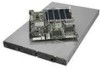
chapter briefly describes the main features of the server system. This chapter provides illustrations of the product, a list of the server system features, and diagrams showing the location of important components and connections on the server system. AF002374 Figure 1. Intel® Server System SR1560SF - Intel SR1560SFHS | Service Guide - Page 26
• Optional support for SW RAID 5 with enablement key • Optional Intel® Remote Management Module 2 • Optional Intel® Remote Management Module 2 NIC National Semiconductor* PC87427 controller On-board ATI* ES1000 video controller with 16 MB DDR SDRAM 4 Intel® Server System SR1560SF Service Guide - Intel SR1560SFHS | Service Guide - Page 27
Status • System Identification Single 600 W power supply • Five non-redundant, monitored and controlled system fans • Two non-redundant fans in power supply • One front panel USB 2.0 port • Two back I/O USB 2.0 ports Intel® System Management Software Intel® Server System SR1560SF Service Guide 5 - Intel SR1560SFHS | Service Guide - Page 28
K Control Panel USB L Control Panel Data M Fan Power Cables BC D Power Supply A Server Board G H I J F E CPU2 CPU1 Fan Module M Optical Drive Module Drive Bays LK Control Panel Module AF002352 Figure 2. Cable Routing for Hot-Swap Drive System 6 Intel® Server System SR1560SF Service Guide - Intel SR1560SFHS | Service Guide - Page 29
to Fixed HDD P SATA Data to HDD 0 Q Optical Drive Data BC D Power Supply A Server Board F G H I PO Q Optical Drive Module CPU1 CPU2 Fan Module J E NM Drive Bays LK Control Panel Module AF002353 Figure 3. Cable Routing for Fixed Drive System Intel® Server System SR1560SF Service Guide 7 - Intel SR1560SFHS | Service Guide - Page 30
or backplane (hot-swap drive system) J. Control panel K. Hard drive bays; 2 - fixed drive system, 3 - hot-swap drive system (drives not included) L. Slimline Optical Drive Bay (drive not included) M. Front bezel (optional) Figure 4. System Components 8 Intel® Server System SR1560SF Service Guide - Intel SR1560SFHS | Service Guide - Page 31
Port Configuration Jumper L. Bridge Board Connector O. CPU Power Connector R. Battery U. SATA0 X. SATA 3 AA. SATA SW RAID 5 Activation Key Connector DD. CMOS Clear Jumper GG. 3-pin IPMB Header Figure 5. Server Board Connector and Component Locations Intel® Server System SR1560SF Service Guide 9 - Intel SR1560SFHS | Service Guide - Page 32
Operation (Default) Jumper Name BIOS Select AF002171 Jumper Purpose If pins 1-2 are jumpered, the BIOS in the lower bank will be selected on the next reset. These pins should be jumpered on 2-3 for normal operation. Figure 6. BIOS Select Jumper 10 Intel® Server System SR1560SF Service Guide - Intel SR1560SFHS | Service Guide - Page 33
for normal operation. See "Resetting the Password" on page -63 for complete password reset instructions. If pins 2-3 are jumpered, BMC Force Update Mode is enabled. These pins should be jumpered on 1-2 for normal operation. Figure 7. Recovery Jumpers Intel® Server System SR1560SF Service Guide 11 - Intel SR1560SFHS | Service Guide - Page 34
is always illuminated (green) when AC power is applied. A B C D G E F AF002160 Figure 8. Light Guided Diagnostic LEDs A. POST Code Diagnostic LEDs B. ID LED C. Status LED D. Memory Fault LEDs E. CPU 2 Fault LED F. CPU 1 Fault LED G. 5VSB LED 12 Intel® Server System SR1560SF Service Guide - Intel SR1560SFHS | Service Guide - Page 35
network connection Network connection in place Transmit/receive activity 10 Mbps connection (if left LED is on or blinking) 100 Mbps connection 1000 Mbps connection Intel® Server System SR1560SF Service Guide 13 - Intel SR1560SFHS | Service Guide - Page 36
system can support either an active SAS backplane (Product Code ASR1500SASBP) or a passive SAS/SATA backplane (Product Code - ASR1500PASBP). The backplanes provide the platform support O. HDD connectors Figure 10. Active/Passive Backplane Components 14 Intel® Server System SR1560SF Service Guide - Intel SR1560SFHS | Service Guide - Page 37
code SR1560SFHS) provides SAS and SATA support. Both systems can be configured for RAID 0, 1, and 10. The Intel® Server System SR1560SF can be configured for SW RAID 5 by using the Intel® RAID Activation Key AXXRAKSW5 accessory. For information on configuring RAID, see the RAID software user's guide - Intel SR1560SFHS | Service Guide - Page 38
provides a lock to secure the hard drive and optical drive area. For instructions on installing the front bezel, see "Installing the Front Bezel". The order number for the bezel is: • ADWBEZBLACK: Black bezel for use with the standard control panel. 16 Intel® Server System SR1560SF Service Guide - Intel SR1560SFHS | Service Guide - Page 39
Interface (optional) E. IO module external connector (optional) F. USB 6 connector G. USB 5 connector H. Video connector I. NIC 2 connector J. NIC 1 connector K. RJ45 serial B port L. PS2 keyboard connector Figure 12. Server System Back AF002187 Intel® Server System SR1560SF Service Guide 17 - Intel SR1560SFHS | Service Guide - Page 40
be used. Note: The USB floppy drive kit is supported on the Intel® Server System SR1560SF - (product code SR1560SFHS) only. For instructions on installing hard drives, see "Installing and Removing a to run at a maximum ambient temperature of 45C. 18 Intel® Server System SR1560SF Service Guide - Intel SR1560SFHS | Service Guide - Page 41
words, install the first system in the rack into the bottom position of the rack, the second system in the second position from the bottom, and so on. Instructions for installing your chassis into a rack are included in each rackmount option kit. Intel® Server System SR1560SF Service Guide 19 - Intel SR1560SFHS | Service Guide - Page 42
20 Intel® Server System SR1560SF Service Guide - Intel SR1560SFHS | Service Guide - Page 43
of this manual. Note: Whenever you service the system, you must first power down the server and unplug all server system as it would be positioned for normal operation. Removing and Installing the Front Bezel The front bezel is available as an optional accessory for the Intel® Server System SR1560SF - Intel SR1560SFHS | Service Guide - Page 44
Removing and Installing the System Cover Removing the System Cover The server system must be operated with the system cover in place to ensure proper cooling. You will need to remove the top cover to add or replace components inside of the server. 22 Intel® Server System SR1560SF Service Guide - Intel SR1560SFHS | Service Guide - Page 45
cover sit just inside the server system sidewalls. 1. Slide the cover forward until it clicks into place (see letter "A"). 2. Insert the screw at the center of the top cover (see letter "B"). A B AF002370 Figure 17. Installing the Server System Cover Intel® Server System SR1560SF Service Guide 23 - Intel SR1560SFHS | Service Guide - Page 46
are installed: remove air dam by rocking it back and forth until it snaps off. Notes: Do not remove the air dam if only one processor is installed. AF002366 Figure 19. Removing the Processor 2 Air Dam (Optional - only if two processors are installed) 24 Intel® Server System SR1560SF Service Guide - Intel SR1560SFHS | Service Guide - Page 47
and options. See "Server System References" for a link to the list of tested DIMMs. Figure 21 shows the supported DIMM configuration that is recommended because it allows both memory branches from the MCH to operate independently and simultaneously. Intel® Server System SR1560SF Service Guide 25 - Intel SR1560SFHS | Service Guide - Page 48
do not have thermal sensors, you must install DIMM Blanks when installing less than 8 FBDIMMs. DIMM Blanks can be ordered through your preferred distributor. 26 Intel® Server System SR1560SF Service Guide - Intel SR1560SFHS | Service Guide - Page 49
the following: (1) Touch the metal chassis before touching the processor or server board. Keep part of your body in contact with the metal chassis to dissipate the static charge while handling the processor. (2) Avoid moving around unnecessarily. Intel® Server System SR1560SF Service Guide 27 - Intel SR1560SFHS | Service Guide - Page 50
(see Figure 23). TP02074 Figure 23. Lifting the Processor Socket Handle 2. Raise the CPU load plate (see Figure 24). A B Figure 24. Installing the Processor TP02075 Note: Do not touch the socket pins; they are very sensitive and easily damaged. 28 Intel® Server System SR1560SF Service Guide - Intel SR1560SFHS | Service Guide - Page 51
sink over the processor, lining up the four captive screws with the four posts surrounding the processor. 2. Loosely screw in the captive screws on the heat sink corners in a diagonal manner. Do no fully tighten one screw before tightening another. Intel® Server System SR1560SF Service Guide 29 - Intel SR1560SFHS | Service Guide - Page 52
the Heat Sink (1U Passive Heat Sink Shown) Removing a Processor 1. Loosen the four server. The steps below describe how to remove and then install the small air baffle. Use these steps only when it is necessary for a component installation process. 30 Intel® Server System SR1560SF Service Guide - Intel SR1560SFHS | Service Guide - Page 53
the Small Air Baffle Installing the Small Air Baffle Lower the baffle into the server system and position baffle over the two stand-off locations. Press into place as shown in the figure below. AF002365 Figure 28. Installing the Small Air Baffle Intel® Server System SR1560SF Service Guide 31 - Intel SR1560SFHS | Service Guide - Page 54
Intel® Server System SR1560SF - product code SR1560SFHS. system cooling. To avoid possible damage to your server system, use only the drive carriers that came with your system. Note: See "Server System References" for an Internet link to a list of supported Intel® Server System SR1560SF Service Guide - Intel SR1560SFHS | Service Guide - Page 55
drive according to the drive manufacturer's instructions. 6. With the drive circuit-side server system. 2. Remove the four screws that attach the hard drive to the drive carrier. Lift the drive from the carrier and store the drive in an anti-static bag. Intel® Server System SR1560SF Service Guide - Intel SR1560SFHS | Service Guide - Page 56
carrier from the server system. 2. Remove the four screws securing the drive blank in place. Save the screws; you will use them to install the hard drive into the carrier. AF002380 Figure 33. Removing the Drive Blank from the Fixed Hard Drive Carrier 34 Intel® Server System SR1560SF Service Guide - Intel SR1560SFHS | Service Guide - Page 57
carrier(s) from the server system. 3. Remove the four screws that attach the hard drive to the carrier. Remove the drive from the carrier and store the drive in an anti-static bag. AF002382 Figure 35. Removing Fixed Hard Drive from the Server System Intel® Server System SR1560SF Service Guide 35 - Intel SR1560SFHS | Service Guide - Page 58
instructions, see "Installing a Fixed Hard Disk Drive". 5. If the hard drive will not be replaced, install a drive blank into the carrier using the four screws you just removed. 6. Install the hard drive carrier into the server system the Drive Tray 36 Intel® Server System SR1560SF Service Guide - Intel SR1560SFHS | Service Guide - Page 59
release lever (see letter "A") to unlock the optical drive tray and remove the slimline optical drive tray assembly from the server system (see letter "B"). A B AF000384 Figure 38. Removing the Slimline Optical Drive Assembly from the Server System Intel® Server System SR1560SF Service Guide 37 - Intel SR1560SFHS | Service Guide - Page 60
Empty Server System Bays A filler panel or drive blank must be installed into an empty drive bay. To access the drive bays, remove the front bezel if it is installed. For instructions, see riser assembly and pull up to release it from the system. 38 Intel® Server System SR1560SF Service Guide - Intel SR1560SFHS | Service Guide - Page 61
Server System 3. Press down uniformly until the two hooks on the rear of the PCI riser assembly engage the server system back panel slots. The riser card will seat into the matching socket on the server board. Ensure that the riser card is fully seated. Intel® Server System SR1560SF Service Guide - Intel SR1560SFHS | Service Guide - Page 62
for information and add-in card requirements. Installing and Removing a PCI Add-in Card The instructions below describe how to install and remove a PCI add-in card. Installing a PCI Add-in Card all empty add-in card slots have filler panels installed. 40 Intel® Server System SR1560SF Service Guide - Intel SR1560SFHS | Service Guide - Page 63
"B"). 3. Install the I/O expansion module cover into the system back panel (see letter "C"). I/O Expansion Module (Dual Gigabit) I/O Expansion Module (External SAS) B A C AF002377 Figure 45. Removing the I/O Expansion Module(s) from the Server Board Intel® Server System SR1560SF Service Guide 41 - Intel SR1560SFHS | Service Guide - Page 64
board to the server board connector and snap the standoff into the matching hole on the server board (see letter "E" in the figure below). A C B E D AF002378 Figure 46. Installing the Intel® RMM2 and the Intel® RMM2 NIC Module to the Server System 42 Intel® Server System SR1560SF Service Guide - Intel SR1560SFHS | Service Guide - Page 65
system back panel. A B C D AF002379 Figure 47. Removing the Intel® RMM and the Intel® RMM NIC Module from the Server System Installing/Replacing the Backplane Board (Hotswap Drive System Only) The instructions power connector (see letter "D"). Intel® Server System SR1560SF Service Guide 43 - Intel SR1560SFHS | Service Guide - Page 66
mechanism (see letter "A") and inserting it into the connector on the server board (see letter "B"). Close the retention mechanism to hold the bridge board in place. B A C A C AF000372 Figure 49. Installing the Bridge Board into the Server System 44 Intel® Server System SR1560SF Service Guide - Intel SR1560SFHS | Service Guide - Page 67
"B")... B B A A AF000373 Figure 50. Removing the Bridge Board from the Server System 3. Disconnect the power from the backplane board (see letter "A"). 4. Loosen the backplane board out of the server system (see letter "D"). A C D B Intel® Server System SR1560SF Service Guide AF002349 45 - Intel SR1560SFHS | Service Guide - Page 68
pins (see letter "C"). 5. Lift the fan board out of the server system (see letter "D"). A B C D AF002351 Figure 52. Removing the Fan Board from the Server System 6. Install a replacement fan board. For instructions, see "Installing the Fan Board". 46 Intel® Server System SR1560SF Service Guide - Intel SR1560SFHS | Service Guide - Page 69
remove memory, processor heat sinks, and processors from the server board. 3. If installed, remove bridge board (hot-swap systems only). 4. If installed, remove the PCI riser assembly. 5. If installed, disconnect all SATA cables from the server board. Intel® Server System SR1560SF Service Guide 47 - Intel SR1560SFHS | Service Guide - Page 70
from the server board (see letter "A") and lift the server board from the server system (see letter "B"). A B AF002346 Figure 54. Removing the Server Board 9. Install the replacement server board. For instructions, see "Installing the Server Board". 48 Intel® Server System SR1560SF Service Guide - Intel SR1560SFHS | Service Guide - Page 71
. 5. Re-connect all SATA cables to the server board. 6. Install the PCI riser assembly. 7. Install the bridge board (hot-swap systems only). 8. Install memory, processor heat sinks, and processors. 9. Install the CPU air duct and blue air baffle. Intel® Server System SR1560SF Service Guide 49 - Intel SR1560SFHS | Service Guide - Page 72
enligt fabrikantens instruktion. Varoitus: Paristo voi räjähtää, jos se on virheellisesti asennettu. Vaihda paristo ainoastaan laitevalmistajan suosittelemaan tyyppiin. Hävitä käytetty paristo valmistajan ohjeiden mukaisesti. 50 Intel® Server System SR1560SF Service Guide - Intel SR1560SFHS | Service Guide - Page 73
or replacing the power supply, you must first take the server out of service, turn off all peripheral devices connected to the system, turn off the system by pressing the power button, and unplug the AC power cord from the system or wall outlet. Intel® Server System SR1560SF Service Guide 51 - Intel SR1560SFHS | Service Guide - Page 74
, use the following instructions. 1. Disconnect all power server out of service, turn off all peripheral devices connected to the system, turn off the system by pressing the power button, and unplug the AC power cord from the system or wall outlet. 52 Intel® Server System SR1560SF Service Guide - Intel SR1560SFHS | Service Guide - Page 75
. 5. Connect the USB and front panel cables to the connectors on the backplane (see letters "B" and "C"). C B A AF002343 Figure 60. Installing Control Panel Module into the Server System (Hot-swap Drive System) Intel® Server System SR1560SF Service Guide 53 - Intel SR1560SFHS | Service Guide - Page 76
"C"). 4. Press the latch at the back of the control panel (see letter "D"). 5. Slide the control panel out through the front of the server system (see letter "E"). A C D B E AF002344 Figure 61. Removing the Control Panel Module (Fixed Drive System) 54 Intel® Server System SR1560SF Service Guide - Intel SR1560SFHS | Service Guide - Page 77
separately. If one of the fans in the power supply fails, the power supply must be replaced. The system fans at the front of the Intel® Server System SR1560SF can be individually replaced if one of them fails. Use the steps below to replace a fan. Intel® Server System SR1560SF Service Guide 55 - Intel SR1560SFHS | Service Guide - Page 78
the fan cable into the matching connector on the backplane or fan board (see letter "B"). B A AF002357 Figure 64. Installing a Fan into the Fan Module 56 Intel® Server System SR1560SF Service Guide - Intel SR1560SFHS | Service Guide - Page 79
. Installing the Rack Handle Removing the Rack Handles Remove the two screws holding the rack handle in place, and remove the rack handle from the server system. AF000378 Figure 66. Removing the Rack Handle Intel® Server System SR1560SF Service Guide 57 - Intel SR1560SFHS | Service Guide - Page 80
58 Intel® Server System SR1560SF Service Guide - Intel SR1560SFHS | Service Guide - Page 81
used to change server configuration defaults. You can run BIOS Setup with or without an operating system being present. See "Server System References" for a link to the Intel® Server Board S5400SF Technical Product Specification where you will find details about specific BIOS setup screens. Starting - Intel SR1560SFHS | Service Guide - Page 82
describes the keyboard commands you can use in the BIOS Setup menus. Table 4. Setup Menu Key Use Key Defaults - Pressing causes the following to appear: Setup Confirmation Load default configuration now? [Yes] [No] If "Yes" is selected and the - Intel SR1560SFHS | Service Guide - Page 83
computer and press when you see the message: Press Key if you want to run SETUP 2. Write down the current settings in the BIOS Setup program. Note: Do not skip step 2. You will need these settings to configure your server at the end of the procedure. Intel® Server System SR1560SF Service - Intel SR1560SFHS | Service Guide - Page 84
from the normal operation position, CMOS Protect at pins 1 and 2, to the CMOS Clear Force Erase position, covering pins 2 and 3. Password Reset BMC Force Update Mode 22 33 Disable Enable 2 CMOS 3 Clear AF002170 Figure 67. Clear CMOS Jumper 62 Intel® Server System SR1560SF Service Guide - Intel SR1560SFHS | Service Guide - Page 85
4. Wait five seconds. 5. Return the Password Reset jumper to the Password Clear Protect position, covering pins 1 and 2. 6. Close the server system. 7. Power up the server. 8. The password is now cleared and can be reset by going into BIOS setup. Intel® Server System SR1560SF Service Guide 63 - Intel SR1560SFHS | Service Guide - Page 86
64 Intel® Server System SR1560SF Service Guide - Intel SR1560SFHS | Service Guide - Page 87
200-240V at 50/60 Hz; 4.3 A max. System Environmental Specifications Table 5. System Environmental Specifications Temperature Non-operating Operating Humidity Non-operating Shock Operating . (23 +/- 2 degrees C). +/-15kV except I/O port +/-8KV, per Intel Environmental Test Specification. - Intel SR1560SFHS | Service Guide - Page 88
66 Intel® Server System SR1560SF Service Guide - Intel SR1560SFHS | Service Guide - Page 89
is available at http:// support.intel.com/support/motherboards/server/s5400sf/. For the fastest service, please submit your form via the Internet. Date Submitted Company Name Contact Name Email Address Intel Server Product Priority (Critical, Hot, High, Low Brief Problem Description. Provide - Intel SR1560SFHS | Service Guide - Page 90
DIMM Configuration DIMM A1 MB and Vendor / part number DIMM A2 MB and Vendor / part number DIMM number DIMM D3 MB and Vendor / part number DIMM D4 MB and Vendor / part number Operating System Information Operating System Version Service Pack 68 Intel® Server System SR1560SF Service Guide - Intel SR1560SFHS | Service Guide - Page 91
Driver Driver Revision IRQ I/O Base FW Address Revision Hard Drive Information Drive Type (SATA/ SAS) Make/Model Hot-swap or Fixed IRQ FW Revision Management Information On-Board Platform Instrumentation only Intel® Remote Management Module Intel® Server System SR1560SF Service Guide - Intel SR1560SFHS | Service Guide - Page 92
Complete Problem Description In the space below, provide a complete description of the steps used to reproduce the problem or a complete description of where the problem can be found. Please also include any details on troubleshooting already done 70 Intel® Server System SR1560SF Service Guide - Intel SR1560SFHS | Service Guide - Page 93
processes, each of which is assigned a specific hex POST code number. As each configuration routine is started, BIOS will display the given POST code to the POST Code Diagnostic LEDs found on the back edge of the server board. To assist in troubleshooting a system hang during the POST process, the - Intel SR1560SFHS | Service Guide - Page 94
memory controller 0x25h OFF G R G Configuring memory parameters in the memory controller 0x26h OFF G A OFF Optimizing memory controller settings 0x27h OFF G A G Initializing memory, such as ECC init 0x28h G OFF R OFF Testing memory 72 Intel® Server System SR1560SF Service Guide - Intel SR1560SFHS | Service Guide - Page 95
console controller Disabling the console controller Enabling the console controller Resetting the keyboard Disabling the keyboard Detecting the presence of the keyboard Enabling the keyboard Intel® Server System SR1560SF Service Guide 73 - Intel SR1560SFHS | Service Guide - Page 96
G R G A OFF R OFF A G R G A Clearing keyboard input buffer Instructing keyboard controller to run Self Test (PS2 only) Resetting the mouse Detecting the mouse Detecting drive detection, etc.) Enabling / configuring a fixed media device Resetting Intel® Server System SR1560SF Service Guide - Intel SR1560SFHS | Service Guide - Page 97
been called) 0xFAh A R A R Operating system has requested the system to reset (ResetSystem () has been called) Pre-EFI Initialization Module (PEIM) / Recovery 0x30h OFF OFF R R Crisis recovery has been initiated because of a user request Intel® Server System SR1560SF Service Guide 75 - Intel SR1560SFHS | Service Guide - Page 98
initiated by software (corrupt flash) OFF G R R Loading crisis recovery capsule OFF G R A Handing off control to the crisis recovery capsule G G A A Unable to complete crisis recovery. 76 Intel® Server System SR1560SF Service Guide - Intel SR1560SFHS | Service Guide - Page 99
to change the pricing for telephone support at any time without notice). Before calling, fill out an "Intel® Server Issue Report Form". A sample form is provided on the following pages. However, for the fastest service, please submit your form via the Internet. For an updated support contact list - Intel SR1560SFHS | Service Guide - Page 100
8 621 33104691 (not toll-free) Hong Kong 852 2 844 4456 India........... 0006517 2 68303634 (manual toll-free. You need an IDD-equipped telephone) Indonesia ... 803 65 7249 Korea ......... 822 767 2595 800 225 288. Once connected, dial 800 843 4481 78 Intel® Server System SR1560SF Service Guide - Intel SR1560SFHS | Service Guide - Page 101
0114 Peru 001 916 377 0114 Uruguay..... 001 916 377 0114 Venezuela... Contact AT&T USA at 0 800 2255 288. Once connected, dial 800 843 4481 Intel® Server System SR1560SF Service Guide 79 - Intel SR1560SFHS | Service Guide - Page 102
80 Intel® Server System SR1560SF Service Guide - Intel SR1560SFHS | Service Guide - Page 103
, you must adhere to the assembly instructions in this guide to ensure and maintain compliance with existing this server board. The final configuration of your end system product may require additional EMC compliance testing. For more information, please contact your local Intel representative. - Intel SR1560SFHS | Service Guide - Page 104
Product Regulatory Compliance References The following table references Server Chassis Compliance and markings that may appear on the product. Markings below are ) FCC CFR 47, Part 15 (Emissions) CANADA ICES-003 CLASS A CANADA NMB-003 CLASSE A 82 Intel® Server System SR1560SF Service Guide - Intel SR1560SFHS | Service Guide - Page 105
International CB Certification IEC60950 CISPR 22 / CISPR 24 None Required Japan VCCI Certification Korea RRL Certification MIC Notice No. 1997-41 (EMC) & 1997-42 (EMI) Intel® Server System SR1560SF Service Guide 83 - Intel SR1560SFHS | Service Guide - Page 106
Russia Ukraine Compliance Reference GOST-R Certification GOST R 2921691 (Emissions) GOST R 5062895 (Immunity) Ukraine Certification Compliance Reference Marking Example None Required Taiwan BSMI CNS13438 R33025 84 Intel® Server System SR1560SF Service Guide - Intel SR1560SFHS | Service Guide - Page 107
of this product, contact: Intel Corporation 5200 N.E. Elam Young Parkway used in accordance with the instructions, may cause harmful interference the modified product. Only peripherals (computer input/output devices, terminals, printers, etc Intel® Server System SR1560SF Service Guide 85 - Intel SR1560SFHS | Service Guide - Page 108
receiver in a domestic environment, it may cause radio interference. Install and use the equipment according to the instruction manual. BSMI (Taiwan) The BSMI Certification Marking and EMC warning is located on the outside rear area of the product. 86 Intel® Server System SR1560SF Service Guide - Intel SR1560SFHS | Service Guide - Page 109
marked on product Product Ecology Compliance Intel has a system in place to restrict the use of banned substances in accordance with world wide product ecology regulatory requirements. The following is Intel's product ecology compliance criteria. Intel® Server System SR1560SF Service Guide 87 - Intel SR1560SFHS | Service Guide - Page 110
materials as defined in Intel's Environmental Product Content Specification of Suppliers and Outsourced Manufacturers - http:// supplier.intel.com/ehs/environmental.htm / part includes a battery which contains Perchlorate material. None Required 88 Intel® Server System SR1560SF Service Guide - Intel SR1560SFHS | Service Guide - Page 111
restricted materials as defined in Intel's Environmental Product Content Specification of Suppliers and Outsourced Manufacturers - http:// supplier.intel.com/ehs/environmental.htm. ISO11469 Recycling Applied to Retail Packaging Only for Boxed Boards Intel® Server System SR1560SF Service Guide 89 - Intel SR1560SFHS | Service Guide - Page 112
supply cords before servicing. Simplified Chinese 2 Traditional Chinese 2 German: Dieses Geräte hat mehr als ein Stromkabel. Um eine Gefahr des elektrischen Schlages zu verringern trennen sie beide (2) Stromkabeln bevor Instandhaltung 90 Intel® Server System SR1560SF Service Guide - Intel SR1560SFHS | Service Guide - Page 113
Updated product information for configurations can be found on the Intel Server Builder Web site at the following URL: http://channel.intel. VDE licensed. Total server configuration is not to exceed the maximum loading conditions of the power supply. Intel® Server System SR1560SF Service Guide 91 - Intel SR1560SFHS | Service Guide - Page 114
End-of-Life / Product Recycling Product recycling and end-of-life take-back systems and requirements vary by country. Contact the retailer or distributor of this product for information about product recycling and / or take-back. 92 Intel® Server System SR1560SF Service Guide - Intel SR1560SFHS | Service Guide - Page 115
will be free from defects in material and workmanship and will substantially conform to Intel's publicly available specifications for a period of three (3) years after the date the Product was purchased from an Intel authorized distributor. Software of any kind delivered with or as part of products - Intel SR1560SFHS | Service Guide - Page 116
causes, including accident, problems with electrical power, usage not in accordance with product instructions, misuse, neglect, alteration Service To obtain warranty service for this Product, you may contact Intel or your authorized distributor. 94 Intel® Server System SR1560SF Service Guide - Intel SR1560SFHS | Service Guide - Page 117
http:// www.intel.com/), call your local distributor or an Intel Customer Support representative. See "Getting Help" for telephone numbers. Returning a Defective Product Before returning any product, call your authorized dealer/distribution authority. Intel® Server System SR1560SF Service Guide 95 - Intel SR1560SFHS | Service Guide - Page 118
96 Intel® Server System SR1560SF Service Guide - Intel SR1560SFHS | Service Guide - Page 119
/Assembly Safety Instructions English The power supply in this product contains no user-serviceable parts. Refer servicing only to system-any unpainted metal surface-when handling components. 6. Do not operate the system with the chassis covers removed. Intel® Server System SR1560SF Service Guide - Intel SR1560SFHS | Service Guide - Page 120
recommended by the equipment manufacturer. Dispose of used batteries according to manufacturer's instructions. The system is designed to operate in a typical office environment. Choose a site that they serve as the product's main power disconnect. 98 Intel® Server System SR1560SF Service Guide - Intel SR1560SFHS | Service Guide - Page 121
Ports ab. 5. Tragen Sie ein geerdetes Antistatik Gelenkband, um elektrostatische Ladungen (ESD) über blanke Metallstellen bei der Handhabung der Komponenten zu vermeiden. 6. Schalten Sie das System niemals ohne ordnungsgemäß montiertes Gehäuse ein. Intel® Server System SR1560SF Service Guide 99 - Intel SR1560SFHS | Service Guide - Page 122
anzubringen: 1. Vergewissern Sie sich, daß Sie keine Werkzeuge oder Teile im Innern des Systems zurückgelassen haben. 2. Überprüfen Sie alle Kabel, Zusatzkarten und andere Komponenten auf Batterien den Anweisungen des Herstellers entsprechend. 100 Intel® Server System SR1560SF Service Guide - Intel SR1560SFHS | Service Guide - Page 123
Français Das System wurde für den Betrieb in einer normalen Büroumgebung entwickelt. Der Standort sollte: • "sauber und staubfrei sein (Hausstaub Pour mettre le système hors tension, vous devez débrancher chaque câble d'alimentation de sa prise. Intel® Server System SR1560SF Service Guide 101 - Intel SR1560SFHS | Service Guide - Page 124
a été sous tension. Faites également attention aux broches aiguës des cartes et aux bords tranchants du capot. Nous vous recommandons l'usage de gants de protection. 102 Intel® Server System SR1560SF Service Guide - Intel SR1560SFHS | Service Guide - Page 125
type ou d'un type équivalent recommandé par le fabricant. Disposez des piles usées selon les instructions du fabricant. Le système a été conçu pour fonctionner dans un cadre de travail normal. alimentación de corriente alterna que tenga el producto Intel® Server System SR1560SF Service Guide 103 - Intel SR1560SFHS | Service Guide - Page 126
sistema y bloquéelo para impedir que pueda accederse al mismo sin autorización. 5. Conecte todos los cables externos y los cables de alimentación CA al sistema. 104 Intel® Server System SR1560SF Service Guide - Intel SR1560SFHS | Service Guide - Page 127
tierra correctamente instalada. • "Provisto de espacio suficiente como para acceder a los cables de alimentación, ya que éstos hacen de medio principal de desconexión del sistema. Intel® Server System SR1560SF Service Guide 105 - Intel SR1560SFHS | Service Guide - Page 128
polso che è attaccata alla presa a terra del telaio del sistema - qualsiasi superficie non dipinta - . 6. Non far operare il sistema quando il telaio è senza le coperture. Intel® Server System SR1560SF Service Guide - Intel SR1560SFHS | Service Guide - Page 129
di una presa a muro correttamente installata. • "Dotata di spazio sufficiente ad accedere ai cavi di alimentazione, i quali rappresentano il mezzo principale di scollegamento del sistema. Intel® Server System SR1560SF Service Guide 107 - Intel SR1560SFHS | Service Guide - Page 130
108 Intel® Server System SR1560SF Service Guide - Intel SR1560SFHS | Service Guide - Page 131
server should be integrated and serviced only by technically qualified persons. You must adhere to the guidelines in this guide and the assembly instructions in your server manuals instructions are not followed. Indicates hot components or surfaces. Intel® Server System SR1560SF Service Guide 109 - Intel SR1560SFHS | Service Guide - Page 132
Information Technology Equipment (ITE), which may be installed in offices, schools, computer rooms, and similar commercial type locations. The suitability of this product for the weight for easier handling, remove any easily detachable components. 110 Intel® Server System SR1560SF Service Guide - Intel SR1560SFHS | Service Guide - Page 133
the exact type required. A separate AC cord is required for each system power supply. Some power supplies in Intel® servers use Neutral Pole Fusing. To avoid risk of shock use caution when working that is /are provided with a suitable earth ground. Intel® Server System SR1560SF Service Guide 111 - Intel SR1560SFHS | Service Guide - Page 134
accessible, and it must be labeled as controlling power to the entire unit, not just to the server(s). To avoid risk of potential electric shock, a proper safety ground must be implemented for the rack and each piece of equipment installed in it. 112 Intel® Server System SR1560SF Service Guide - Intel SR1560SFHS | Service Guide - Page 135
radiation exposure and/or personal injury: • Do not open the enclosure of any laser peripheral or device • Laser peripherals or devices have are not user serviceable • Return to manufacturer for servicing Intel® Server System SR1560SF Service Guide 113 - Intel SR1560SFHS | Service Guide - Page 136
hin, der bei Nichtbeachtung der Sicherheitshinweise zu schweren oder tödlichen Verletzungen führen kann. Weist auf Verbrennungsgefahr an heißen Bauteilen bzw. Oberflächen hin. 114 Intel® Server System SR1560SF Service Guide - Intel SR1560SFHS | Service Guide - Page 137
Geräte erzeugt werden. • In gewittergefährdeten Gebieten sollten Sie das System an einen Überspannungsschutz anschließen und bei einem Gewitter die Telekommunikationskabel zum lassen, um das Gewicht zu reduzieren und die Handhabung zu erleichtern. Intel® Server System SR1560SF Service Guide 115 - Intel SR1560SFHS | Service Guide - Page 138
vom Stromnetz. Die Steckdose muß in der Nähe der Anlage angebracht und gut erreichbar sein. • Netzkabel müssen an eine ordnungsgemäß geerdete Steckdose angeschlossen sein. 116 Intel® Server System SR1560SF Service Guide - Intel SR1560SFHS | Service Guide - Page 139
vor, und bauen Sie das schwerste Gerät an der untersten Position im Rack ein. Ziehen Sie jeweils immer nur ein Gerät aus dem Rack heraus. Intel® Server System SR1560SF Service Guide 117 - Intel SR1560SFHS | Service Guide - Page 140
aus dem Server mit der Bauelementseite Systems ohne Abdeckung kann zur Beschädigung von Systemkomponenten führen. So bringen Sie die Abdeckung wieder an: • Vergewissern Sie sich zunächst, daß Sie keine Werkzeuge oder Teile im Gehäuse vergessen haben. 118 Intel® Server System SR1560SF Service Guide - Intel SR1560SFHS | Service Guide - Page 141
uniquement par des techniciens qualifiés. Vous devez suivre les informations de ce guide et les instructions d'assemblage des manuels de serveur pour vérifier et maintenir la conformité et peuvent figurer sur le produit ou sur son emballage. Intel® Server System SR1560SF Service Guide 119 - Intel SR1560SFHS | Service Guide - Page 142
soleil et les radiateurs. • À l'écart des sources de vibration ou des chocs physiques. • Isolé des champs électromagnétiques importants produits par des appareils électriques. 120 Intel® Server System SR1560SF Service Guide - Intel SR1560SFHS | Service Guide - Page 143
ou de supprimer un composant non connectable à chaud. Les alimentations de certains serveurs Intel sont munies de doubles fusibles pôle/neutre: veuillez observer les précautions d'usage afin d'alimentation. L'intérieur de celui-ci est soumis à des Intel® Server System SR1560SF Service Guide 121 - Intel SR1560SFHS | Service Guide - Page 144
Les cordons d'alimentation doivent répondre aux critères suivants : - Le cordon d'alimentation doit supporter une intensité supérieure à celle indiquée sur le produit. - Le cordon d'alimentation doit télécommunication qui sont connectés au système. 122 Intel® Server System SR1560SF Service Guide - Intel SR1560SFHS | Service Guide - Page 145
le montage en rack Le rack doit être fixé à un support inamovible pour éviter qu'il ne bascule lors de l'extension l'équipement. Le rack doit être installé conformément aux instructions du fabricant. Installez les équipements dans le rack en partant Intel® Server System SR1560SF Service Guide 123 - Intel SR1560SFHS | Service Guide - Page 146
système. • Vérifiez que les câbles, les cartes d'extension et les autres composants sont correctement installés. • Fixez les panneaux au châssis en suivant les instructions du produit. 124 Intel® Server System SR1560SF Service Guide - Intel SR1560SFHS | Service Guide - Page 147
irse a las directrices de esta guía y a las instrucciones de montaje de los manuales del servidor para asegurar y mantener el cumplimiento con las certificaciones y homologaciones existentes de los graves si no se tiene en cuenta la ADVERTENCIA. Intel® Server System SR1560SF Service Guide 125 - Intel SR1560SFHS | Service Guide - Page 148
conectada a tierra. • Provista de espacio suficiente para acceder a los cables de la fuente de alimentación ya que constituyen la desconexión principal de la alimentación. 126 Intel® Server System SR1560SF Service Guide - Intel SR1560SFHS | Service Guide - Page 149
conexión en funcionamiento. Algunas fuentes de alimentación de electricidad de los servidores de Intel utilizan el polo neutral del fuselaje. Para evitar riesgos de choques electricos use precaució , adquiera alguno cuyo uso esté aprobado en su país. Intel® Server System SR1560SF Service Guide 127 - Intel SR1560SFHS | Service Guide - Page 150
para repararla. • Apague el servidor y desconecte todos los cables de alimentación antes de agregar o reemplazar cualquier componente que no es de conexión en funcionamiento. 128 Intel® Server System SR1560SF Service Guide - Intel SR1560SFHS | Service Guide - Page 151
evitar el riesgo de descargas eléctricas, deberá instalar una conexión a tierra apropiada para el bastidor y para cada pieza del equipo instalada en el mismo. Intel® Server System SR1560SF Service Guide 129 - Intel SR1560SFHS | Service Guide - Page 152
equipo. Deseche las baterías respetando la normativa local. No intente recargar la batería. No intente desmontar, pinchar o causar cualquier otro desperfecto a una batería. 130 Intel® Server System SR1560SF Service Guide - Intel SR1560SFHS | Service Guide - Page 153
caja de ningún periférico o dispositivo láser • Los periféricos o dispositivos láser no pueden ser reparados por el usuario • Haga que el fabricante los repare Intel® Server System SR1560SF Service Guide 131 - Intel SR1560SFHS | Service Guide - Page 154
132 Intel® Server System SR1560SF Service Guide - Intel SR1560SFHS | Service Guide - Page 155
ITE ITE 场地选择 5V Intel® Server System SR1560SF Service Guide 133 - Intel SR1560SFHS | Service Guide - Page 156
134 Intel® Server System SR1560SF Service Guide - Intel SR1560SFHS | Service Guide - Page 157
ESD) ESD ESD ESD ESD Intel® Server System SR1560SF Service Guide 135 - Intel SR1560SFHS | Service Guide - Page 158
其他危险 替换电池 136 Intel® Server System SR1560SF Service Guide
-
 1
1 -
 2
2 -
 3
3 -
 4
4 -
 5
5 -
 6
6 -
 7
7 -
8
-
9
-
10
-
11
-
12
-
13
-
14
-
15
-
16
-
17
-
18
-
19
-
20
-
21
-
22
-
23
-
24
-
25
-
26
-
27
-
28
-
29
-
30
-
31
-
32
-
33
-
34
-
35
-
36
-
37
-
38
-
39
-
40
-
41
-
42
-
43
-
44
-
45
-
46
-
47
-
48
-
49
-
50
-
51
-
52
-
53
-
54
-
55
-
56
-
57
-
58
-
59
-
60
-
61
-
62
-
63
-
64
-
65
-
66
-
67
-
68
-
69
-
70
-
71
-
72
-
73
-
74
-
75
-
76
-
77
-
78
-
79
-
80
-
81
-
82
-
83
-
84
-
85
-
86
-
87
-
88
-
89
-
90
-
91
-
92
-
93
-
94
-
95
-
96
-
97
-
98
-
99
-
100
-
101
-
102
-
103
-
104
-
105
-
106
-
107
-
108
-
109
-
110
-
111
-
112
-
113
-
114
-
115
-
116
-
117
-
118
-
119
-
120
-
121
-
122
-
123
-
124
-
125
-
126
-
127
-
128
-
129
-
130
-
131
-
132
-
133
-
134
-
135
-
136
-
137
-
138
-
139
-
140
-
141
-
142
-
143
-
144
-
145
-
146
-
147
-
148
-
149
-
150
-
151
-
152
-
153
-
154
-
155
-
156
-
157
-
158
 |
 |

Intel
®
Server System SR1560SF
Service Guide
A Guide for Technically Qualified Assemblers of Intel® Identified Subassemblies/
Products
Intel Order Number D92960-00
4