Intel SR1600UR Service Guide
Intel SR1600UR - Server System - 0 MB RAM Manual
 |
UPC - 735858206723
View all Intel SR1600UR manuals
Add to My Manuals
Save this manual to your list of manuals |
Intel SR1600UR manual content summary:
- Intel SR1600UR | Service Guide - Page 1
Intel® Server System SR1600UR Service Guide A Guide for Technically Qualified Assemblers of Intel® Identified Subassemblies/ Products Intel Order Number E52880-005 - Intel SR1600UR | Service Guide - Page 2
are trademarks or registered trademarks of Intel Corporation or its subsidiaries in the United States and other countries. * Other names and brands may be claimed as the property of others. Copyright © 2008-2011, Intel Corporation. All Rights Reserved ii Intel® Server System SR1600UR Service Guide - Intel SR1600UR | Service Guide - Page 3
for navigating through the BIOS Setup screens, performing a BIOS update, and resetting the password or BIOS defaults. The back of this manual provides technical specifications, regulatory information, "getting help" information, and the warranty. Intel® Server System SR1600UR Service Guide iii - Intel SR1600UR | Service Guide - Page 4
iv Intel® Server System SR1600UR Service Guide - Intel SR1600UR | Service Guide - Page 5
de este documento antes de realizar cualquiera de las instrucciones. Vea Intel Server Boards and Server Chassis Safety Information en el Intel® Server Deployment Toolkit 3.0 CD y/o en http://www.intel.com/support/motherboards/server/sb/cs-010770.htm. Intel® Server System SR1600UR Service Guide v - Intel SR1600UR | Service Guide - Page 6
vi Intel® Server System SR1600UR Service Guide - Intel SR1600UR | Service Guide - Page 7
the contacts inside the jumper, causing intermittent problems with the function controlled by that jumper. Take care to grip with, but not squeeze, the pliers or other tool you use to remove a jumper, or you may bend or break the pins on the board. Intel® Server System SR1600UR Service Guide vii - Intel SR1600UR | Service Guide - Page 8
viii Intel® Server System SR1600UR Service Guide - Intel SR1600UR | Service Guide - Page 9
...25 RAID Support ...26 Advanced Management Options 26 Intel® Remote Management Module 3 26 Rack Mount Options ...27 Chapter 3: Hardware Installations and Upgrades 29 Before You Begin ...29 Tools and Supplies Needed 29 System References ...29 Intel® Server System SR1600UR Service Guide ix - Intel SR1600UR | Service Guide - Page 10
System Only) . 57 Installing a Fixed Mount Hard Disk Drive 57 Removing a Fixed Mount Hard Disk Drive 60 Installing and Removing a Hot-swap Hard Drive (Hot-swap Hard Drive System Only) ...... 61 Installing a Hot-swap SAS or SATA Hard Disk Drive 61 x Intel® Server System SR1600UR Service Guide - Intel SR1600UR | Service Guide - Page 11
...99 Preparing for the Upgrade 99 Upgrading the BIOS 100 Clearing the Password ...100 Restoring the BIOS Defaults 102 Appendix A: Technical Reference 103 600-W Single Power Supply Input Voltages 103 600-W Single Power Supply Output Voltages 104 Intel® Server System SR1600UR Service Guide xi - Intel SR1600UR | Service Guide - Page 12
147 Intended Application Uses 148 Site Selection ...148 Equipment Handling Practices 148 Power and Electrical Warnings 149 System Access Warnings 150 Rack Mount Warnings 150 Electrostatic Discharge (ESD 151 Other Hazards ...151 Deutsch ...152 xii Intel® Server System SR1600UR Service Guide - Intel SR1600UR | Service Guide - Page 13
Sicherheitshinweise für den Server 152 Sicherheitshinweise und Vorsichtsmaßnahmen 152 Zielbenutzer der Anwendung 153 Standortauswahl ...153 Handhabung von Ger sobre el montaje en bastidor 167 Descarga electrostática (ESD 167 Otros riesgos ...168 Intel® Server System SR1600UR Service Guide xiii - Intel SR1600UR | Service Guide - Page 14
xiv Intel® Server System SR1600UR Service Guide - Intel SR1600UR | Service Guide - Page 15
Cover 51 Figure 38. Removing the Processor Protective Cover 51 Figure 39. Installing the Processor 52 Figure 40. Closing the Load Plate 52 Figure 41. Installing the Heatsink (1U Passive Heatsink Shown 53 Figure 42. Removing the Heatsink 55 Intel® Server System SR1600UR Service Guide xv - Intel SR1600UR | Service Guide - Page 16
87 Figure 77. Removing Power Supply Module from the Server System 88 Figure 78. Installing Power Supply Module into the Server System 88 Figure 79. Jumper 101 Figure 88. BIOS Default Jumper 102 Figure 89. Diagnostic LED Placement Diagram 114 xvi Intel® Server System SR1600UR Service Guide - Intel SR1600UR | Service Guide - Page 17
103 Table 6. Power Supply Output Capability 104 Table 7. System Environmental Specifications 105 Table 8. POST Progress Code LED Example 113 Table 9. Diagnostic LED POST Code Decoder 114 Table 10. Product Regulatory Compliance Markings 126 Intel® Server System SR1600UR Service Guide xvii - Intel SR1600UR | Service Guide - Page 18
xviii Intel® Server System SR1600UR Service Guide - Intel SR1600UR | Service Guide - Page 19
Product Specification. The contents of each server system are listed below. Intel® Server System SR1600UR Contents Your Intel® Server System SR1600UR (fixed mount hard drive system) ships with the following items: • Intel® Server Board S5520UR, installed in the server system • One 600-W power supply - Intel SR1600UR | Service Guide - Page 20
the hardware box • Rack handles, in the hardware box • Attention document, in the server system product box • Quick Start User's Guide, in the server system product box • Intel® Server Deployment Toolkit 3.0 CD • Intel® System Management Software DVD 2 Intel® Server System SR1600UR Service Guide - Intel SR1600UR | Service Guide - Page 21
S5520UR Technical Product Specification Available at: http://www.intel.com/p/en_US/support/highlights/server/s5520ur Intel® Server System SR1600UR Quick Start User's Guide Available in the product box Accessories or other Intel server products Spares, Parts List, and Configuration Guide Available - Intel SR1600UR | Service Guide - Page 22
power budget For software to manage your Intel® server Power Budget Analysis Tool Available at: http://www.intel.com/p/en_US/support/highlights/server/s5520ur Intel® System Management Software Available at: http://www.intel.com/go/servermanagement/ 4 Intel® Server System SR1600UR Service Guide - Intel SR1600UR | Service Guide - Page 23
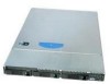
the server system. This chapter provides illustrations of the product, a list of the server system features, and diagrams showing the location of important components and connections on the server system. AF002746 Figure 1. Intel® Server System SR1600UR Intel® Server System SR1600UR Service Guide - Intel SR1600UR | Service Guide - Page 24
of the server system. Table 2. Intel® Server System SR1600UR Feature Summary Feature Dimensions Server Board Processor Memory Chipset Description • 1.703 inches (43.3 mm) high • 16.90 inches (430 mm) wide • 27.19 inches (690.6 mm) deep • 34 pounds (15.4 kg) - max chassis weight Intel® Server Board - Intel SR1600UR | Service Guide - Page 25
RAID levels 0/1/10 • Optional support for SW RAID 5 with activation key • Slimline bay for slimline SATA optical drive • One PCI Express* X16 Add-in Card slot (Gen 2) • Standard control panel • Hot-swap hard drive system only: Intel® Local Control Panel Intel® Server System SR1600UR Service Guide - Intel SR1600UR | Service Guide - Page 26
-redundant 40-mm power supply fans On-board ServerEngines* LLC Pilot II Controller • Integrated Baseboard Management Controller (Integrated BMC), IPMI 2.0 compliant • Integrated Super I/O on LPC interface Support for Intel® System Management Software 8 Intel® Server System SR1600UR Service Guide - Intel SR1600UR | Service Guide - Page 27
): • Three fixed hard drives supported in fixed mount hard drive system • Three hot-swap drives supported in hot- swap hard drive system L. Slimline Optical Drive Bay (drive not included) M. Front bezel (optional Figure 2. Server System Components Intel® Server System SR1600UR Service Guide 9 - Intel SR1600UR | Service Guide - Page 28
LEDs on the fan board (in the fixed mount hard drive system - see Figure 4) or hot-swap backplane (in the hot-swap hard drive system - see Figure 5) help identify failed and failing fans. The fan fault LEDs turn on (amber) if there is a fan fault. 10 Intel® Server System SR1600UR Service Guide - Intel SR1600UR | Service Guide - Page 29
LED G. CPU 2 Fan Fault LED I. CPU 2 DIMM Fault LEDs B. System Identification LED D. Memory 1 Fan Fault LED F. CPU 1 DIMM Fault LEDs H. Memory 2 Fan Fault LED J. 5V Standby LED Figure 3. Intel® Light-Guided Diagnostic LEDs - Server Board AF002833 Intel® Server System SR1600UR Service Guide 11 - Intel SR1600UR | Service Guide - Page 30
Intel® Light-Guided Diagnostic LEDs - Fan Board E D C B A AF003001 A. Fan 1 Fault LED C. Fan 3 Fault LED E. Fan 5 Fault LED B. Fan 2 Fault LED D. Fan 4 Fault LED Figure 5. Intel® Light-Guided Diagnostic LEDs - Hot-swap Backplane (Passive Shown) 12 Intel® Server System SR1600UR Service Guide - Intel SR1600UR | Service Guide - Page 31
A B AF003002 A. Status LED B. System Identification LED Figure 6. Intel® Light-Guided Diagnostic LEDs - Standard Control Panel Intel® Server System SR1600UR Service Guide 13 - Intel SR1600UR | Service Guide - Page 32
Server Board Components AB C D DD CC E FG H I J BB AA Z Y X W V U T S R QPO K L NM AF002696 14 Intel® Server System SR1600UR Service Guide - Intel SR1600UR | Service Guide - Page 33
L. Processor 2 Socket O. Bridge Board Connector (Intel® Server Chassis) R. 2x4 Power Connector U. System 2 Fan Header X. System 1 Fan Header AA. SGPIO Header DD. I/O Module Mezzanine Connector 1 Figure 7. Server Board Connector and Component Locations Intel® Server System SR1600UR Service Guide - Intel SR1600UR | Service Guide - Page 34
. If pins 2-3 are jumpered, the system can only boot from EFIbootable recovery media with the recovery BIOS image. The main system BIOS will not boot. These pins should be jumpered on 1-2 for normal system operation. Figure 8. Configuration Jumpers 16 Intel® Server System SR1600UR Service Guide - Intel SR1600UR | Service Guide - Page 35
not included) B. Control panel (Standard control panel shown) C. Hard Drive Status LEDs (hot-swap drives only) D. Hard drive bays (drives not included) Figure 9. Optional Peripherals Intel® Server System SR1600UR Service Guide 17 - Intel SR1600UR | Service Guide - Page 36
a floppy drive, the AXXUSBFLOPPY accessory kit must be used. Note: The USB floppy drive kit is supported on the Intel® Server System SR1600UR (Product Code: SR1600URHS) only. For instructions on installing hard drives, see the following sections: • "Installing and Removing a Fixed Mount Hard Drive - Intel SR1600UR | Service Guide - Page 37
the system is in sleep or ACPI S1 state. No light indicates the power is off or the system is in ACPI S4 or S5 state. Random blinking green light indicates hard disk drive activity (SAS or SATA). No light indicates no hard disk drive activity. Intel® Server System SR1600UR Service Guide 19 - Intel SR1600UR | Service Guide - Page 38
supported in the hot-swap hard drive system (Product Code: SR1600URHS). For instructions on installing the standard control panel, see "Replacing the Control Panel Module (Hot-swap Hard Drive System only)" on page 88. A B C D E F O N ML KJ I H G TP02099 20 Intel® Server System SR1600UR Service - Intel SR1600UR | Service Guide - Page 39
, Scroll Left Menu Control Button, Enter System Identification LED Power/Sleep LED Power/Sleep Button System Status LED NIC 2 Activity LED NIC system. Allows you to attach a USB component to the front of the system. Figure 11. Intel® Local Control Panel Intel® Server System SR1600UR Service Guide - Intel SR1600UR | Service Guide - Page 40
Power Receptacle C. IO module external connector (optional) D. Management Network Interface (optional) E. NIC 1 connector F. NIC 2 connector G. Four USB 2.0 connectors H. Video connector I. RJ-45 serial B port connector Figure 12. Server System Back Panel 22 Intel® Server System SR1600UR Service - Intel SR1600UR | Service Guide - Page 41
network connection Network connection in place Transmit/receive activity 10 Mbps connection (if right LED is on or blinking) 100 Mbps connection 1000 Mbps connection Intel® Server System SR1600UR Service Guide 23 - Intel SR1600UR | Service Guide - Page 42
RAID Activation Key D. Fan 5 Power E. Bridge Board Connector F. Fan 4 Power G. Fan 3 Power H. Fan 2 Power I. Front Panel Connector J. Fan 1 Power K. Screw L. Front Panel USB M. Hot-swap SAS/SATA Connectors Figure 14. Active SAS Backplane Components 24 Intel® Server System SR1600UR Service Guide - Intel SR1600UR | Service Guide - Page 43
1 E. Fan 5 Power F. Bridge Board Connector G. Fan 4 Power H. Fan 3 Power I. Fan 2 Power J. Front Panel Connector K. Fan 1 Power L. Screw M. Front Panel USB N. SATA 2 O. Hot-swap SAS/SATA Connectors Figure 15. Passive SAS/SATA Backplane Components Intel® Server System SR1600UR Service Guide 25 - Intel SR1600UR | Service Guide - Page 44
Redirection allowing USB devices attached to the remote system to be used on the managed server. For instructions on installing the Intel® Remote Management Module 3, see "Installing and Removing the Intel® Remote Management Module 3" on page 70. 26 Intel® Server System SR1600UR Service Guide - Intel SR1600UR | Service Guide - Page 45
rack, the second system in the second position from the bottom, and so on. For instructions on installing your system into a rack, see "Removing and Installing from a Rack" on page 33. These instructions are also included in each rackmount option kit. Intel® Server System SR1600UR Service Guide 27 - Intel SR1600UR | Service Guide - Page 46
28 Intel® Server System SR1600UR Service Guide - Intel SR1600UR | Service Guide - Page 47
working with your server product, pay close attention to the "Safety Information" on page v at the beginning of this manual. Note: Whenever you service the system, you must first power down the server and unplug all peripheral devices and the AC power cord. Tools and Supplies Needed • Phillips - Intel SR1600UR | Service Guide - Page 48
Drive C Power Supply Server Board CPU1 E F G H LM R S HDD0 Optical Drive Module CPU2 Fan Module D I Fan Board NO HDD1 PQ HDD2 J K Drive Bays Control Panel Module Figure 16. Cable Routing (Fixed Mount Hard Drive System) AF002876 30 Intel® Server System SR1600UR Service Guide - Intel SR1600UR | Service Guide - Page 49
system, route the following cables through the air baffle notches (as shown in Figure 17): • Main Power Cable • CPU Power Cable • Power Signal Cable • Optical Drive Data Cable • SATA 0-2 HDD Data Cables • SATA 0-2 HDD Power Mount Hard Drive System) Intel® Server System SR1600UR Service Guide 31 - Intel SR1600UR | Service Guide - Page 50
(Hot-swap Hard Drive System) AF002875 Cabling Around the Small Air Baffle In a hot-swap hard drive system, route the following cables through the air baffle notches (as shown in Figure 19): • Main Power Cable • CPU Power Cable • Power Signal Cable 32 Intel® Server System SR1600UR Service Guide - Intel SR1600UR | Service Guide - Page 51
removed from the rack before servicing. • Tool-less sliding rail kit Only the tool-less rail kit allows you to service the server system while installed in a rack. Note: Follow all safety guidelines while removing a system from a rack to avoid injury. Intel® Server System SR1600UR Service Guide 33 - Intel SR1600UR | Service Guide - Page 52
of the chassis with the finger tab facing outward and located closer to the rear of the chassis. 4. Align the holes in the rail with the tabs on the chassis and place the rail against the chassis. 5. Slide the front screw installed loosely in step 15. 34 Intel® Server System SR1600UR Service Guide - Intel SR1600UR | Service Guide - Page 53
: The rail flanges mount to the inside of each post. 5. Insert the inner rails over the server chassis sidewall studs. 6. Slide the inner rails toward the front of the server chassis. 7. Secure the inner rails with one #6-32 x 1/4 screw for each rail. Intel® Server System SR1600UR Service Guide 35 - Intel SR1600UR | Service Guide - Page 54
. Note the orientation in the figures below - the control panel is at the right. If you are installing a bezel on your server system, make sure you position it as shown. TP02197 Figure 20. Front View with Bezel supporting the Standard Control Panel 36 Intel® Server System SR1600UR Service Guide - Intel SR1600UR | Service Guide - Page 55
steps: 1. At each end of the bezel, line up the center notch on the bezel with the center guide on the rack handles. 2. Push the bezel onto the front of the server system until it clicks into place. Figure 22. Installing the Front Bezel AF002770 Intel® Server System SR1600UR Service Guide 37 - Intel SR1600UR | Service Guide - Page 56
button at the top of the server system in (see letter "B" in Figure 24), slide the top cover back until it stops (see letter "C" in Figure 24). 3. Insert your finger in the notch (see letter "D" in Figure 24) and lift the cover upward to remove it. 38 Intel® Server System SR1600UR Service Guide - Intel SR1600UR | Service Guide - Page 57
the cover sit just inside the server system sidewalls. 2. Slide the cover forward until it clicks into place (see letter "A" in Figure 25). 3. (Optional) Insert the safety screw at the center of the top cover (see letter "B" in Figure 25) if required. Intel® Server System SR1600UR Service Guide 39 - Intel SR1600UR | Service Guide - Page 58
B A TP02196 Figure 25. Installing the Server System Cover 40 Intel® Server System SR1600UR Service Guide - Intel SR1600UR | Service Guide - Page 59
26). A A Riser Card Connector B AF002894 Figure 26. Removing PCI Riser Assembly from the Server System Caution: Place the riser assembly upside down to avoid damage to the riser card connector. 4. , see "Replacing a PCI Riser Card" on page 43. Intel® Server System SR1600UR Service Guide 41 - Intel SR1600UR | Service Guide - Page 60
engage the server system back panel slots. The riser card seats into the matching sockets on the server board. 4. Connect any cables to add-in cards that require them. See your add-in card documentation for information and add-in card requirements. 42 Intel® Server System SR1600UR Service Guide - Intel SR1600UR | Service Guide - Page 61
PCI riser assembly into the server system. For instructions, see "Installing the PCI Riser Assembly" on page 42. 8. Connect any cables to add-in cards that require them. See your add-in card documentation for information and add-in card requirements. Intel® Server System SR1600UR Service Guide 43 - Intel SR1600UR | Service Guide - Page 62
remove a PCI add-in card. Installing a PCI Add-in Card To install a PCI add-in card, follow these steps: 1. Remove the PCI riser assembly. For instructions, see "Removing the PCI Riser Assembly" on page 41. 44 Intel® Server System SR1600UR Service Guide - Intel SR1600UR | Service Guide - Page 63
instructions, see "Removing the PCI Riser Assembly" on page 41. 2. Remove the screw securing the add-in card to the add-in card slot (see letter "A" in Figure 31) . 3. Remove the PCI add-in card from the riser card connector (see letter "B" in Figure 31). Intel® Server System SR1600UR Service Guide - Intel SR1600UR | Service Guide - Page 64
Air Duct To remove the processor air duct, follow these steps: 1. Remove the PCI riser assembly. For instructions, see "Removing the PCI Riser Assembly" on page 41. 2. Lift the processor air duct from its location over the two processor sockets. 46 Intel® Server System SR1600UR Service Guide - Intel SR1600UR | Service Guide - Page 65
the Processor Air Duct Installing and Removing Memory The silkscreen on the board displays DIMM A1, DIMM A2, DIMM B1, DIMM B2, DIMM C1, DIMM C2 for DIMMs on CPU socket 1 and DIMM D1, DIMM D2, DIMM E1, DIMM E2, DIMM F1, DIMM F2 for DIMMs on CPU socket 2. Intel® Server System SR1600UR Service Guide - Intel SR1600UR | Service Guide - Page 66
E2 AF002884 Figure 34. Installing the Memory 4. Make sure the clips at either end of the DIMM socket(s) are pushed outward to the open position (see letter "A" in Figure 34). 5. Holding the DIMM by the edges, remove it from its anti-static package. 48 Intel® Server System SR1600UR Service Guide - Intel SR1600UR | Service Guide - Page 67
processor; failure to remove the cover could result in damage to the system. Installing the Processor To install a processor, follow these instructions: 1. Remove the PCI riser assembly. For instructions, see "Removing the PCI Riser Assembly" on page 41. Intel® Server System SR1600UR Service Guide - Intel SR1600UR | Service Guide - Page 68
on page 46. 3. Remove the heatsink, if installed. For instructions, see "Removing the Heatsink" on page 54. 4. Locate the processor socket. 5. Push the lever handle down and away from cover for use when removing a processor that will not be replaced. 50 Intel® Server System SR1600UR Service Guide - Intel SR1600UR | Service Guide - Page 69
38. Removing the Processor Protective Cover 11. Orient the processor with the socket such that the orientation notches on the processor align with the two orientation posts on the socket, and insert the processor into the socket (see Figure 39). Intel® Server System SR1600UR Service Guide 51 - Intel SR1600UR | Service Guide - Page 70
Heatsink You must install the processor before installing the heatsink. For instructions, see "Installing the Processor" on page 49. Caution replacing a processor, make sure there is adequate TIM present on the heatsink to support processor cooling. 52 Intel® Server System SR1600UR Service Guide - Intel SR1600UR | Service Guide - Page 71
through the system. 3. Set the heatsink over the processor, lining up the four captive screws with the four posts surrounding the processor. 4. Air Flow 1 4 TIM Chassis Front AF002841 Figure 41. Installing the Heatsink (1U Passive Heatsink Shown) Intel® Server System SR1600UR Service Guide 53 - Intel SR1600UR | Service Guide - Page 72
slightly to break the seal between the heatsink and the processor. ii. Lift the heatsink from the processor. If it does not pull up easily, twist the heatsink again. Do not force the heatsink from the processor. Doing so could damage the processor. 54 Intel® Server System SR1600UR Service Guide - Intel SR1600UR | Service Guide - Page 73
6. Open the CPU load plate (see Figure 36). 7. Remove the processor. 8. If installing a replacement processor, see "Installing the Processor" on page 49 for instructions. Otherwise, install the protective socket cover over the empty processor socket. Intel® Server System SR1600UR Service Guide 55 - Intel SR1600UR | Service Guide - Page 74
Air Baffle Installing the Small Air Baffle To install the small air baffle, follow these steps: 1. Lower the baffle into the server system and position the baffle over the two standoff locations. 2. Snap the baffle into place as shown in Figure 44. 56 Intel® Server System SR1600UR Service Guide - Intel SR1600UR | Service Guide - Page 75
to the system, turn off the system by pressing the power button, and unplug the AC power cord from the system or wall outlet. You can install up to three fixed SATA hard drives in the Intel® Server System SR1600UR (Product Code: SR1600UR). Note: For a web link to a list of supported hardware, see - Intel SR1600UR | Service Guide - Page 76
antistatic surface. 5. Set any jumpers and/or switches on the drive according to the drive manufacturer's instructions. 6. With the drive circuit-side down, position the connector end of the drive so that it plastic retention device (see Figure 47). 58 Intel® Server System SR1600UR Service Guide - Intel SR1600UR | Service Guide - Page 77
SATA power connector(s) to each installed hard drive (see letter "C" in Figure 48). Cable Connector DrivFeix0ed DeOvipcteical DrivFeix1ed DrivFeix2ed SupPpolwy er A SATA 0 SATA 1 SATA 2 Backplane SABTaAckDrViiveew of C B Power Data AF003018 Intel® Server System SR1600UR Service Guide 59 - Intel SR1600UR | Service Guide - Page 78
removed. Note: To maintain proper system cooling, all hard drive carriers must be installed in the server system and populated with either a drive or a drive blank. 5. Slide the hard drive carrier into the server system until it clicks into place. 60 Intel® Server System SR1600UR Service Guide - Intel SR1600UR | Service Guide - Page 79
swap Hard Drive (Hotswap Hard Drive System Only) You may install up to three hot-swap SAS or SATA drives in the Intel® Server System SR1600UR (Product Code: SR1600URHS). Cautions: If you install less "B" in Figure 51) and store it for future use. Intel® Server System SR1600UR Service Guide 61 - Intel SR1600UR | Service Guide - Page 80
into the server system and push all the way until it stops (see letter "A" in Figure 53). 9. Close the lever to lock the drive assembly into place (see letter "B" in Figure 53). A B AF002946 Figure 53. Installing Drive Assemby into the Server System 62 Intel® Server System SR1600UR Service Guide - Intel SR1600UR | Service Guide - Page 81
this location. Note: A USB Floppy drive is not supported in the Intel® Server System SR1600UR with fixed mount hard drives (Product Code: SR1600UR). For a web link to a list of supported hardware, see "Additional Information and Software" on page 3. Intel® Server System SR1600UR Service Guide 63 - Intel SR1600UR | Service Guide - Page 82
cables back into the chassis opening as you insert the device. Push the device all the way from the front until it clicks (see letter "C" in Figure 55). 8. Verify that the blue release lever on the tray (see letter "D" in Figure 55) locks into place. 64 Intel® Server System SR1600UR Service Guide - Intel SR1600UR | Service Guide - Page 83
end of the cable to one of the SATA connectors on the server board (see letter "B" in Figure 56). Server Board A SATA Cable Server Board SATA Connectors SupPpolywer SATA Conn. Detail AF002889 Figure 56. Connecting the Optical Device Data Cable Intel® Server System SR1600UR Service Guide 65 - Intel SR1600UR | Service Guide - Page 84
power and data cables from the rear of the optical device. 3. Press the blue release lever (from inside the chassis) to unlock the optical drive tray and remove the slimline optical drive tray assembly from the server system to remove it from the tray. 66 Intel® Server System SR1600UR Service Guide - Intel SR1600UR | Service Guide - Page 85
Server System Bays You must install either a filler panel, drive blank, or empty drive carrier into an empty drive bay. To access the drive bays, remove the front bezel if it is installed. For instructions into any remaining empty hard drive bays. Intel® Server System SR1600UR Service Guide 67 - Intel SR1600UR | Service Guide - Page 86
the I/O expansion module over the server board as shown in Figure 59. 6. First fit the front of the module into the back panel slot(s), and then attach the module to the server board connector and engage the standoffs (see letter "C" in Figure 59). 68 Intel® Server System SR1600UR Service Guide - Intel SR1600UR | Service Guide - Page 87
46. 3. Disconnect the I/O expansion module from the server board connector and the standoffs and remove the module out of the server system (see letter "A" in Figure 60). 4. Remove the standoffs from the server board (see letter "B" in Figure 60). Intel® Server System SR1600UR Service Guide 69 - Intel SR1600UR | Service Guide - Page 88
Remote Management Module 3, follow these steps: 1. Remove the PCI riser assembly. For instructions, see "Removing the PCI Riser Assembly" on page 41. 2. Remove the processor air duct. For instructions, see "Removing the Processor Air Duct" on page 46. 70 Intel® Server System SR1600UR Service Guide - Intel SR1600UR | Service Guide - Page 89
the Intel® RMM3 to the module bracket with two screws (see Figure 62). Top View AF002948 Figure 62. Installing the Intel® RMM3 to the bracket 5. Connect one end of the cable (labeled 'RMM3') to the RMM3 connector on the Intel® RMM3 (see Figure 63). Intel® Server System SR1600UR Service Guide 71 - Intel SR1600UR | Service Guide - Page 90
the Server System 8. Install the processor air duct. For instructions, see "Installing the Processor Air Duct" on page 47. 9. Install the PCI riser assembly into the server system. For instructions, see "Installing the PCI Riser Assembly" on page 42. 72 Intel® Server System SR1600UR Service Guide - Intel SR1600UR | Service Guide - Page 91
Disconnect the Intel® RMM3 from the connector on the server board (see letter "B" in Figure 65) and remove the module out of the server system (see letter "C" in Figure 65). C A B AF002858 Figure 65. Removing the Intel® RMM3 from the Server System Intel® Server System SR1600UR Service Guide 73 - Intel SR1600UR | Service Guide - Page 92
, see "Removing the Processor Air Duct" on page 46. 3. Disconnect all fan cables from the fan board. 4. Disconnect the power cable from the fan board (see letter "A" in Figure 67). 5. Remove the screw from the fan board (see letter "B" in Figure 67). 74 Intel® Server System SR1600UR Service Guide - Intel SR1600UR | Service Guide - Page 93
7. Lift the fan board out of the server system (see letter "D" in Figure 67). A B C D AF002905 Figure 67. Removing the Fan Board from the Server System 8. Install a replacement fan board. For instructions, see "Installing the Fan Board" on page 76. Intel® Server System SR1600UR Service Guide 75 - Intel SR1600UR | Service Guide - Page 94
to the fan board. 5. Install the processor air duct. For instructions, see "Installing the Processor Air Duct" on page 47. 6. Install the PCI riser assembly into the server system. For instructions, see "Installing the PCI Riser Assembly" on page 42. 76 Intel® Server System SR1600UR Service Guide - Intel SR1600UR | Service Guide - Page 95
(Hotswap Hard Drive System Only) The Intel® Server System SR1600UR with hot-swap drives (Product Code: SR1600URHS) requires that you install a hot-swap backplane to make the system operational. Two backplane options are supported: • Active SAS RAID Backplane, capable of supporting SAS hard drives - Intel SR1600UR | Service Guide - Page 96
on both ends (see letter "A" in Figure 70) b. Insert the bridge board into the bridge board connector on the backplane and server board (see letter "B" in Figure 70). Make sure that the connector edges on both sides align correctly with the slots. 78 Intel® Server System SR1600UR Service Guide - Intel SR1600UR | Service Guide - Page 97
panel to the USB connector and front panel connector on the backplane (see letter "B" in Figure 71). 10. Connect the power cable to the power connector on the backplane (see letter "C" in Figure 71). 11. Passive backplane only: Do the following: Intel® Server System SR1600UR Service Guide 79 - Intel SR1600UR | Service Guide - Page 98
SATA cables. 12. Install the processor air duct. For instructions, see "Installing the Processor Air Duct" on page 47. 13. Install the PCI riser assembly into the server system. For instructions, see "Installing the PCI Riser Assembly" on page 42. 80 Intel® Server System SR1600UR Service Guide - Intel SR1600UR | Service Guide - Page 99
Board from the Server System 5. Loosen the thumbscrew on the backplane board (see letter "A" in Figure 73). 6. Hold the backplane board only by the edges and slide the backplane board in the direction shown to release it (see letter "B" in Figure 73). Intel® Server System SR1600UR Service Guide 81 - Intel SR1600UR | Service Guide - Page 100
of the server system (see letter "D" in Figure 73). C B Active Backplane A D AF002904 Figure 73. Removing the Backplane from the Server System 8. Install a replacement backplane. For instructions, see "Installing the Backplane Board" on page 77. 82 Intel® Server System SR1600UR Service Guide - Intel SR1600UR | Service Guide - Page 101
. For instructions, see "Removing DIMMs" on page 49 and "Removing the Heatsink" on page 54. 11. Remove the nine screws from the server board (see letter "A" in Figure 74) and lift the server board from the server system (see letter "B" in Figure 74). Intel® Server System SR1600UR Service Guide 83 - Intel SR1600UR | Service Guide - Page 102
To install the server board, follow these steps: 1. Place the server board into the server system (see letter "A" in Figure 75). 2. Attach the server board with screws at the nine locations identified by black arrows (see letter "B" in Figure 75). 84 Intel® Server System SR1600UR Service Guide - Intel SR1600UR | Service Guide - Page 103
to the server board. 10. Install the blue air baffle. For instructions, see "Installing the Small Air Baffle" on page 56. 11. If necessary, install the I/O expansion module. For instructions, see "Installing the I/O Expansion Module" on page 68. Intel® Server System SR1600UR Service Guide 85 - Intel SR1600UR | Service Guide - Page 104
equivalent, under the tab in the plastic retainer. Gently push down on the screwdriver to lift the battery. 5. Remove the battery from its socket. 86 Intel® Server System SR1600UR Service Guide - Intel SR1600UR | Service Guide - Page 105
fails. To replace the power supply, follow these steps: 1. Disconnect all power cables. 2. Lift the power supply to disengage it from the latch (see letter "A" in Figure 77) and remove the power supply by sliding it out (see letter "B" in Figure 77). Intel® Server System SR1600UR Service Guide 87 - Intel SR1600UR | Service Guide - Page 106
AC power cord from the system or wall outlet. 1. Unplug the front panel and USB cables from the backplane (see letters "A" and "B" in Figure 79). 2. Press the latch at the back of the control panel and push it forward (see letter "C" in Figure 79). 88 Intel® Server System SR1600UR Service Guide - Intel SR1600UR | Service Guide - Page 107
the control panel cables through the chassis opening (see letter "C" in Figure 80). 6. Slide the replacement control panel into the server system (see letter "D" in Figure 80 D AF002950 Figure 80. Installing Control Panel Module into the Server System Intel® Server System SR1600UR Service Guide 89 - Intel SR1600UR | Service Guide - Page 108
4 in "Removing the Backplane Board" on page 81 5. Disconnect the fan power cables from the backplane board (see letter "A" in Figure 81). 6. Press latch (see letter "B" in Figure 81) and slide fan assembly to the left (see letter "C" in Figure 81). 90 Intel® Server System SR1600UR Service Guide - Intel SR1600UR | Service Guide - Page 109
the Fan Assembly AF003020 Installing the System Fan Assembly To install the system fan assembly, follow these steps: 1. Lower the system fan assembly into place (see letter "A" in Figure 82) and slide it to the right (see letter "B" in Figure 82). Intel® Server System SR1600UR Service Guide 91 - Intel SR1600UR | Service Guide - Page 110
the Small Air Baffle" on page 56. 5. Install the processor air duct. For instructions, see "Installing the Processor Air Duct" on page 47. 6. Install the PCI riser assembly. For instructions, see "Installing the PCI Riser Assembly" on page 42. 92 Intel® Server System SR1600UR Service Guide - Intel SR1600UR | Service Guide - Page 111
the power supply fails, the power supply must be replaced. The system fans at the front of the Intel® Server System SR1600UR can be individually replaced if one of them fails. Use the following steps to replace a dual rotor fan. 1. If installed, remove the PCI riser assembly. For instructions, see - Intel SR1600UR | Service Guide - Page 112
Rack Handles Installing the Rack Handles Align the rack handle with the two holes on the side of the server system and attach the rack handle to the server system with two screws as shown in Figure 85. AF000377 Figure 85. Installing the Rack Handle 94 Intel® Server System SR1600UR Service Guide - Intel SR1600UR | Service Guide - Page 113
Removing the Rack Handles Remove the two screws holding the rack handle in place, and remove the rack handle from the server system as shown in Figure 86. AF000378 Figure 86. Removing the Rack Handle Intel® Server System SR1600UR Service Guide 95 - Intel SR1600UR | Service Guide - Page 114
96 Intel® Server System SR1600UR Service Guide - Intel SR1600UR | Service Guide - Page 115
options, which is used to change server configuration defaults. You can run BIOS Setup with or without an operating system being present. For information about specific BIOS setup screens, see the Intel® Server Board S5520UR Technical Product Specification. See "Additional Information and Software - Intel SR1600UR | Service Guide - Page 116
discarded. Setup Defaults - Pressing causes the following to appear: Setup Confirmation Load default configuration now? [Yes] [No] If "Yes" is selected and the key is pressed, all pressed without affecting any existing field values. 98 Intel® Server System SR1600UR Service Guide - Intel SR1600UR | Service Guide - Page 117
Save Configuration changes and instructions. Recording the Current BIOS Settings 1. Boot the computer and press when you see the message: Press Key if you want to run SETUP 2. Write down the current settings in the BIOS Setup program. Intel® Server System SR1600UR Service Guide - Intel SR1600UR | Service Guide - Page 118
Review the instructions and release notes that are provided in the readme file distributed with the BIOS image file before attempting a BIOS upgrade. The release notes contain critical information regarding jumper settings, specific pins 2 and 3). 100 Intel® Server System SR1600UR Service Guide - Intel SR1600UR | Service Guide - Page 119
Jumper 5. Wait ten seconds. 6. Return the Password Clear jumper to the Password Clear Protect position (covering pins 1 and 2). 7. Close the server system. 8. Power up the server. The password is now cleared and can be reset by going into BIOS setup. Intel® Server System SR1600UR Service Guide 101 - Intel SR1600UR | Service Guide - Page 120
5. Wait five seconds. 6. Return the BIOS Default jumper to the normal position (covering pins 1 and 2). 7. Close the server system. 8. Power up the system. The BIOS defaults settings are now restored and can be reset by going into the BIOS setup. 102 Intel® Server System SR1600UR Service Guide - Intel SR1600UR | Service Guide - Page 121
Technical Reference 600-W Single Power Supply Input Voltages The power supply must operate within all specified limits over the input voltage range shown in the following table. Table 5. Power Supply current is measured at 100 VAC and 200 VAC. Intel® Server System SR1600UR Service Guide 103 - Intel SR1600UR | Service Guide - Page 122
% 20 A 20 A 30 A 20 A 3.0 A 6 A Warning: Do not exceed a combined power output of 90 Watts for the +5 V and +3.3 V outputs. Exceeding a combined 90 Watts will overload the power subsystem and may cause the power supplies to overheat and malfunction. 104 Intel® Server System SR1600UR Service Guide - Intel SR1600UR | Service Guide - Page 123
Trapezoidal, 25 g, velocity change 136 inches/sec (> 40 lbs to < 80 lbs) Sound Power: 7.0 BA in an idle state at typical office ambient temperature (23 +/- 2°C). +/-15 KV except I/O port +/- 8 KV per Intel® Environment test specification. 2550 BTU/Hr Intel® Server System SR1600UR Service Guide 105 - Intel SR1600UR | Service Guide - Page 124
106 Intel® Server System SR1600UR Service Guide - Intel SR1600UR | Service Guide - Page 125
on the baseboard System BIOS Version: Intel® Remote Management Module Firmware Version (if applicable): Intel® Management Module BMC Revision (if applicable) : BMC/mBMC Version: FRU/SDR Version: HSC Version: Has the latest BIOS been tried? (Yes/No): Intel® Server System SR1600UR Service Guide 107 - Intel SR1600UR | Service Guide - Page 126
Processor 1 Processor 2 Processor 3 Processor 4 Type Speed sSpec Thermal Solution Thermal solution (Heatsink) examples: (1U, Passive w/air ducting, Active w/fan, etc Memory: Manufacturer Part Number DRAM Part Number On Intel tested list? 108 Intel® Server System SR1600UR Service Guide - Intel SR1600UR | Service Guide - Page 127
(Example: RedHat* Enterprise Linux, Microsoft* Windows* Server 2003, Service pack 1, OEM CD): Manufacturer: Version: Language version (English, Arabic, Chinese (Simplified)): Service Pack Level or Kernel Revision: Distribution (OEM/Retail Intel® Server System SR1600UR Service Guide 109 - Intel SR1600UR | Service Guide - Page 128
RAID driver been tried? (Yes/No): RAID volumes configuration (disks & RAID level): RAID volume use (Boot device/Data Volume): Is BBU (Battery Backup Unit) installed? (Yes/No): BBU part number Detailed description of issue: Troubleshooting tried: 110 Intel® Server System SR1600UR Service Guide - Intel SR1600UR | Service Guide - Page 129
provide a brief description below. Have you returned systems or components to your place of purchase because of this issue? If yes, please provide a brief description below. *All other brands and names are property of their respective owners. Intel® Server System SR1600UR Service Guide 111 - Intel SR1600UR | Service Guide - Page 130
112 Intel® Server System SR1600UR Service Guide - Intel SR1600UR | Service Guide - Page 131
specific hex POST code number. As each configuration routine is started, the BIOS displays the POST code to the POST Code Diagnostic LEDs found on the back edge of the server board. To assist in troubleshooting a system 0 1 1 0 0 Result Ah Ch Intel® Server System SR1600UR Service Guide 113 - Intel SR1600UR | Service Guide - Page 132
memory mode No Usable Memory Error: No memory in the system, or SPD bad so no memory could be detected Channel Training Error: DQ/DQS training failed on a channel during memory channel initialization. Memory Test Error: memory failed Hardware BIST. 114 Intel® Server System SR1600UR Service Guide - Intel SR1600UR | Service Guide - Page 133
X XXX Power-on initialization of the host processor (bootstrap processor) X X X OX XXO Host processor cache initialization (including AP) X X X O X X OX Starting application processor initialization X X X OX X OO SMM initialization Intel® Server System SR1600UR Service Guide 115 - Intel SR1600UR | Service Guide - Page 134
#3 #2 #1 #0 Chipset 0x21h X X O X X XXO Initializing a chipset component Memory 0x22h 0x23h 0x24h 0x25h 0x26h 0x27h 0x28h X X O X X X OX Reading configuration data from memory (SPD on DIMM) bus X OX O O XXO Reserved for USB devices 116 Intel® Server System SR1600UR Service Guide - Intel SR1600UR | Service Guide - Page 135
O X XXO O X X O X X OX O X X O X X OO O X X O X OX X O X X O X OX O Mouse (USB only) Resetting SATA bus and all devices Reserved for ATA Resetting SMBUS Reserved for SMBUS Resetting the Instructing keyboard controller to run Self Test (PS2 only) Intel® Server System SR1600UR Service Guide - Intel SR1600UR | Service Guide - Page 136
device selection 2 O OX OX X OO Trying to boot device selection 3 O O X O X OX X Trying to boot device selection 4 O OX OX OX O Trying to boot device selection 5 118 Intel® Server System SR1600UR Service Guide - Intel SR1600UR | Service Guide - Page 137
by a beep code) 0xE4h 0xE5h 0xE6h O O O X X OX X Entered EFI driver execution (DXE) phase O OOX X OX O Started dispatching drivers O O O X X OOX Started connecting drivers DXE Drivers 0xE7h O OOX O OX O Waiting for user input Intel® Server System SR1600UR Service Guide 119 - Intel SR1600UR | Service Guide - Page 138
Runtime Phase/EFI Operating System Boot 0xF2h 0xF4h 0xF5h 0xF8h 0xF9h 0xFAh O O O O X X OX Signal that the OS has switched to virtual memory mode O O O crisis recovery capsule X X O O O OOO Unable to complete crisis recovery capsule 120 Intel® Server System SR1600UR Service Guide - Intel SR1600UR | Service Guide - Page 139
Latest BIOS, firmware, drivers and utilities - Product documentation, installation and quick start guides - Full product specifications, technical advisories and errata - Compatibility documentation for memory, hardware add-in cards, chassis support matrix and operating systems - Server and chassis - Intel SR1600UR | Service Guide - Page 140
122 Intel® Server System SR1600UR Service Guide - Intel SR1600UR | Service Guide - Page 141
further evaluation. Product Safety Compliance • UL60950 - CSA 60950 (USA/Canada) • EN60950 (Europe) • IEC60950 (International) • CB Certificate & Report, IEC60950 (report to include all country national deviations) • GS Certification (Germany) Intel® Server System SR1600UR Service Guide 123 - Intel SR1600UR | Service Guide - Page 142
(Europe) • IRAM Certification (Argentina) Product EMC Compliance - Class A Compliance • FCC /ICES-003 - Emissions (USA/Canada) Verification • CISPR 22 - Emissions ( (Belarus) • Ukraine Certification (Ukraine) • KCC Certification (EMI) (Korea) 124 Intel® Server System SR1600UR Service Guide - Intel SR1600UR | Service Guide - Page 143
Intel products. For more reference on material restrictions and compliance you can view Intel's Environmental Product Content Specification at http://supplier.intel Declarations • NRTL Certification (US/Canada) • CE Declaration of Product Recycling Marks Intel® Server System SR1600UR Service Guide - Intel SR1600UR | Service Guide - Page 144
guide. Table 10. Product Regulatory Compliance Markings Regulatory Compliance cULus Listing Marks Country USA/Canada Marking GS Mark Germany CE Mark Europe FCC Marking (Class A) USA EMC Marking (Class A) Canada VCCI Marking (Class A) Japan 126 Intel® Server System SR1600UR Service Guide - Intel SR1600UR | Service Guide - Page 145
Table 10. Product Regulatory Compliance Markings Regulatory Compliance BSMI Certification Number & Class A Warning Country Taiwan Marking GOST R Mark Europe China Restriction of Hazardous Substance Environmental Friendly Use Period Mark China Intel® Server System SR1600UR Service Guide 127 - Intel SR1600UR | Service Guide - Page 146
Table 10. Product Regulatory Compliance Markings Regulatory Compliance China Recycling Mark Country China and Chapter 33: Best Management Practices for Perchlorate Materials. This product may include a battery which contains Perchlorate material. 128 Intel® Server System SR1600UR Service Guide - Intel SR1600UR | Service Guide - Page 147
skall anslutas till jordat uttag, när den ansluts till ett nätverk." "Laite on liitettävä suojamaadoituskoskettimilla varustettuun pistorasiaan." "Connect only to a properly earth grounded outlet." Stand-by power Intel® Server System SR1600UR Service Guide 129 - Intel SR1600UR | Service Guide - Page 148
to an unmovable support to prevent it from falling over when one or more servers are extended in server will be used. If AC power supplies are installed: Mains AC power disconnection: The AC power cord(s) is considered the mains disconnect for the server Intel® Server System SR1600UR Service Guide - Intel SR1600UR | Service Guide - Page 149
connectors that plug into the AC receptacle on the server must be an approved IEC (International Electrotechnical Commission) 320, sheet C13, type female connector. • Cord length and flexibility: Cords must be less than 4.5 meters (14.76 feet) long. Intel® Server System SR1600UR Service Guide 131 - Intel SR1600UR | Service Guide - Page 150
questions related to the EMC performance of this product, contact: Intel Corporation 5200 N.E. Elam Young Parkway Hillsboro, OR 97124 not installed and used in accordance with the instructions, may cause harmful interference to radio communications. However Intel® Server System SR1600UR Service Guide - Intel SR1600UR | Service Guide - Page 151
ICES-003 (Canada) Cet appareil numérique respecte les limites bruits radioélectriques equipment according to the instruction manual. BSMI (Taiwan) The BSMI Certification Marking and EMC warning is located on the outside rear area of the product. Intel® Server System SR1600UR Service Guide 133 - Intel SR1600UR | Service Guide - Page 152
Storage Devices: must be UL recognized or UL listed accessory and TUV or VDE Certificationd. Maximum power rating of any one device is 19 watts. Total server configuration is not to exceed the maximum loading conditions of the power supply. 134 Intel® Server System SR1600UR Service Guide - Intel SR1600UR | Service Guide - Page 153
5. Provide some electrostatic discharge (ESD) protection by wearing an antistatic wrist strap attached to chassis ground of the system-any unpainted metal surface-when handling components. 6. Do not operate the system with the chassis covers removed. Intel® Server System SR1600UR Service Guide 135 - Intel SR1600UR | Service Guide - Page 154
chassis covers before turning on the system. Operating the system without the covers in place can damage system to manufacturer's instructions. The system is designed to power supply cord(s), because they serve as the product's main power disconnect. 136 Intel® Server System SR1600UR Service Guide - Intel SR1600UR | Service Guide - Page 155
Ports ab. 5. Tragen Sie ein geerdetes Antistatik Gelenkband, um elektrostatische Ladungen (ESD) über blanke Metallstellen bei der Handhabung der Komponenten zu vermeiden. 6. Schalten Sie das System niemals ohne ordnungsgemäß montiertes Gehäuse ein. Intel® Server System SR1600UR Service Guide 137 - Intel SR1600UR | Service Guide - Page 156
anzubringen: 1. Vergewissern Sie sich, daß Sie keine Werkzeuge oder Teile im Innern des Systems zurückgelassen haben. 2. Überprüfen Sie alle Kabel, Zusatzkarten und andere Komponenten auf Batterien den Anweisungen des Herstellers entsprechend. 138 Intel® Server System SR1600UR Service Guide - Intel SR1600UR | Service Guide - Page 157
Français Das System wurde für den Betrieb in einer normalen Büroumgebung entwickelt. Der Standort sollte: • "sauber und staubfrei sein (Hausstaub le système est branché doit se situer à proximité de l'équipement et être facilement accessible. Intel® Server System SR1600UR Service Guide 139 - Intel SR1600UR | Service Guide - Page 158
a été sous tension. Faites également attention aux broches aiguës des cartes et aux bords tranchants du capot. Nous vous recommandons l'usage de gants de protection. 140 Intel® Server System SR1600UR Service Guide - Intel SR1600UR | Service Guide - Page 159
type ou d'un type équivalent recommandé par le fabricant. Disposez des piles usées selon les instructions du fabricant. Le système a été conçu pour fonctionner dans un cadre de travail normal. alimentación de corriente alterna que tenga el producto Intel® Server System SR1600UR Service Guide 141 - Intel SR1600UR | Service Guide - Page 160
sistema y bloquéelo para impedir que pueda accederse al mismo sin autorización. 5. Conecte todos los cables externos y los cables de alimentación CA al sistema. 142 Intel® Server System SR1600UR Service Guide - Intel SR1600UR | Service Guide - Page 161
. Rivolgersi ad un tecnico specializzato per la riparazione dei componenti dell'alimentazione di questo prodotto. È possibile che il prodotto disponga di più fonti di alimentazione. Intel® Server System SR1600UR Service Guide 143 - Intel SR1600UR | Service Guide - Page 162
e chiudere a chiave il lucchetto sul retro del sistema per impedire l'accesso non autorizzato al sistema. 5. Ricollegare tutti i cavi esterni e le prolunghe AC del sistema. 144 Intel® Server System SR1600UR Service Guide - Intel SR1600UR | Service Guide - Page 163
di una presa a muro correttamente installata. • "Dotata di spazio sufficiente ad accedere ai cavi di alimentazione, i quali rappresentano il mezzo principale di scollegamento del sistema. Intel® Server System SR1600UR Service Guide 145 - Intel SR1600UR | Service Guide - Page 164
146 Intel® Server System SR1600UR Service Guide - Intel SR1600UR | Service Guide - Page 165
if the WARNING is ignored. Indicates potential hazard if indicated information is ignored. Indicates shock hazards that result in serious injury or death if safety instructions are not followed. Indicates hot components or surfaces. Intel® Server System SR1600UR Service Guide 147 - Intel SR1600UR | Service Guide - Page 166
. • Use mechanical assistance or other suitable assistance when moving and lifting equipment. • To reduce the weight for easier handling, remove any easily detachable components. 148 Intel® Server System SR1600UR Service Guide - Intel SR1600UR | Service Guide - Page 167
are the main disconnect device to AC power. The socket outlet(s) must be near the equipment and readily accessible for disconnection. • The power supply cord(s) must be plugged into socket-outlet(s) that is /are provided with a suitable earth ground. Intel® Server System SR1600UR Service Guide 149 - Intel SR1600UR | Service Guide - Page 168
accessible, and it must be labeled as controlling power to the entire unit, not just to the server(s). To avoid risk of potential electric shock, a proper safety ground must be implemented for the rack and each piece of equipment installed in it. 150 Intel® Server System SR1600UR Service Guide - Intel SR1600UR | Service Guide - Page 169
the system. • Check that cables, add-in boards, and other components are properly installed. • Attach the covers to the chassis according to the product instructions. Laser devices have are not user serviceable • Return to manufacturer for servicing Intel® Server System SR1600UR Service Guide 151 - Intel SR1600UR | Service Guide - Page 170
hin, der bei Nichtbeachtung der Sicherheitshinweise zu schweren oder tödlichen Verletzungen führen kann. Weist auf Verbrennungsgefahr an heißen Bauteilen bzw. Oberflächen hin. 152 Intel® Server System SR1600UR Service Guide - Intel SR1600UR | Service Guide - Page 171
Geräte erzeugt werden. • In gewittergefährdeten Gebieten sollten Sie das System an einen Überspannungsschutz anschließen und bei einem Gewitter die Telekommunikationskabel zum lassen, um das Gewicht zu reduzieren und die Handhabung zu erleichtern. Intel® Server System SR1600UR Service Guide 153 - Intel SR1600UR | Service Guide - Page 172
vom Stromnetz. Die Steckdose muß in der Nähe der Anlage angebracht und gut erreichbar sein. • Netzkabel müssen an eine ordnungsgemäß geerdete Steckdose angeschlossen sein. 154 Intel® Server System SR1600UR Service Guide - Intel SR1600UR | Service Guide - Page 173
vor, und bauen Sie das schwerste Gerät an der untersten Position im Rack ein. Ziehen Sie jeweils immer nur ein Gerät aus dem Rack heraus. Intel® Server System SR1600UR Service Guide 155 - Intel SR1600UR | Service Guide - Page 174
aus dem Server mit der Bauelementseite Systems ohne Abdeckung kann zur Beschädigung von Systemkomponenten führen. So bringen Sie die Abdeckung wieder an: • Vergewissern Sie sich zunächst, daß Sie keine Werkzeuge oder Teile im Gehäuse vergessen haben. 156 Intel® Server System SR1600UR Service Guide - Intel SR1600UR | Service Guide - Page 175
uniquement par des techniciens qualifiés. Vous devez suivre les informations de ce guide et les instructions d'assemblage des manuels de serveur pour vérifier et maintenir la conformité et peuvent figurer sur le produit ou sur son emballage. Intel® Server System SR1600UR Service Guide 157 - Intel SR1600UR | Service Guide - Page 176
soleil et les radiateurs. • À l'écart des sources de vibration ou des chocs physiques. • Isolé des champs électromagnétiques importants produits par des appareils électriques. 158 Intel® Server System SR1600UR Service Guide - Intel SR1600UR | Service Guide - Page 177
ou de supprimer un composant non connectable à chaud. Les alimentations de certains serveurs Intel sont munies de doubles fusibles pôle/neutre: veuillez observer les précautions d'usage afin d'alimentation. L'intérieur de celui-ci est soumis à des Intel® Server System SR1600UR Service Guide 159 - Intel SR1600UR | Service Guide - Page 178
Les cordons d'alimentation doivent répondre aux critères suivants : - Le cordon d'alimentation doit supporter une intensité supérieure à celle indiquée sur le produit. - Le cordon d'alimentation doit télécommunication qui sont connectés au système. 160 Intel® Server System SR1600UR Service Guide - Intel SR1600UR | Service Guide - Page 179
le montage en rack Le rack doit être fixé à un support inamovible pour éviter qu'il ne bascule lors de l'extension l'équipement. Le rack doit être installé conformément aux instructions du fabricant. Installez les équipements dans le rack en partant Intel® Server System SR1600UR Service Guide 161 - Intel SR1600UR | Service Guide - Page 180
système. • Vérifiez que les câbles, les cartes d'extension et les autres composants sont correctement installés. • Fixez les panneaux au châssis en suivant les instructions du produit. 162 Intel® Server System SR1600UR Service Guide - Intel SR1600UR | Service Guide - Page 181
irse a las directrices de esta guía y a las instrucciones de montaje de los manuales del servidor para asegurar y mantener el cumplimiento con las certificaciones y homologaciones existentes de los graves si no se tiene en cuenta la ADVERTENCIA. Intel® Server System SR1600UR Service Guide 163 - Intel SR1600UR | Service Guide - Page 182
conectada a tierra. • Provista de espacio suficiente para acceder a los cables de la fuente de alimentación ya que constituyen la desconexión principal de la alimentación. 164 Intel® Server System SR1600UR Service Guide - Intel SR1600UR | Service Guide - Page 183
conexión en funcionamiento. Algunas fuentes de alimentación de electricidad de los servidores de Intel utilizan el polo neutral del fuselaje. Para evitar riesgos de choques electricos use precaució , adquiera alguno cuyo uso esté aprobado en su país. Intel® Server System SR1600UR Service Guide 165 - Intel SR1600UR | Service Guide - Page 184
para repararla. • Apague el servidor y desconecte todos los cables de alimentación antes de agregar o reemplazar cualquier componente que no es de conexión en funcionamiento. 166 Intel® Server System SR1600UR Service Guide - Intel SR1600UR | Service Guide - Page 185
y otros componentes. Recomendamos que realice todos los procedimientos en una estación de trabajo protegida contra descargas electrostáticas. En caso de que no haya una Intel® Server System SR1600UR Service Guide 167 - Intel SR1600UR | Service Guide - Page 186
dentro del sistema. • Compruebe que los cables, tarjetas adicionales y otros componentes están instalados correctamente. • Sujete las cubiertas a la carcasa siguiendo las instrucciones del producto. 168 Intel® Server System SR1600UR Service Guide - Intel SR1600UR | Service Guide - Page 187
caja de ningún periférico o dispositivo láser. • Los periféricos o dispositivos láser no pueden ser reparados por el usuario. • Haga que el fabricante los repare. Intel® Server System SR1600UR Service Guide 169 - Intel SR1600UR | Service Guide - Page 188
170 Intel® Server System SR1600UR Service Guide
-
 1
1 -
 2
2 -
 3
3 -
 4
4 -
 5
5 -
 6
6 -
 7
7 -
8
-
9
-
10
-
11
-
12
-
13
-
14
-
15
-
16
-
17
-
18
-
19
-
20
-
21
-
22
-
23
-
24
-
25
-
26
-
27
-
28
-
29
-
30
-
31
-
32
-
33
-
34
-
35
-
36
-
37
-
38
-
39
-
40
-
41
-
42
-
43
-
44
-
45
-
46
-
47
-
48
-
49
-
50
-
51
-
52
-
53
-
54
-
55
-
56
-
57
-
58
-
59
-
60
-
61
-
62
-
63
-
64
-
65
-
66
-
67
-
68
-
69
-
70
-
71
-
72
-
73
-
74
-
75
-
76
-
77
-
78
-
79
-
80
-
81
-
82
-
83
-
84
-
85
-
86
-
87
-
88
-
89
-
90
-
91
-
92
-
93
-
94
-
95
-
96
-
97
-
98
-
99
-
100
-
101
-
102
-
103
-
104
-
105
-
106
-
107
-
108
-
109
-
110
-
111
-
112
-
113
-
114
-
115
-
116
-
117
-
118
-
119
-
120
-
121
-
122
-
123
-
124
-
125
-
126
-
127
-
128
-
129
-
130
-
131
-
132
-
133
-
134
-
135
-
136
-
137
-
138
-
139
-
140
-
141
-
142
-
143
-
144
-
145
-
146
-
147
-
148
-
149
-
150
-
151
-
152
-
153
-
154
-
155
-
156
-
157
-
158
-
159
-
160
-
161
-
162
-
163
-
164
-
165
-
166
-
167
-
168
-
169
-
170
-
171
-
172
-
173
-
174
-
175
-
176
-
177
-
178
-
179
-
180
-
181
-
182
-
183
-
184
-
185
-
186
-
187
-
188
 |
 |

Intel
®
Server System SR1600UR
Service Guide
A Guide for Technically Qualified Assemblers of Intel
®
Identified Subassemblies/
Products
Intel Order Number E52880-005