Intel SR1630HGP Service Guide
Intel SR1630HGP - Server System - 0 MB RAM Manual
 |
UPC - 735858211901
View all Intel SR1630HGP manuals
Add to My Manuals
Save this manual to your list of manuals |
Intel SR1630HGP manual content summary:
- Intel SR1630HGP | Service Guide - Page 1
Intel® Server System SR1630GP / SR1630HGP Service Guide A Guide for Technically Qualified Assemblers of Intel® Identified Subassemblies/ Products Intel Order Number E73400-004 - Intel SR1630HGP | Service Guide - Page 2
or registered trademarks of Intel Corporation or its subsidiaries in the United States and other countries. * Other names and brands may be claimed as the property of others. Copyright © 2010, Intel Corporation. All Rights Reserved ii Intel® Server System SR1630GP / SR1630HGP Service Guide - Intel SR1630HGP | Service Guide - Page 3
antes de realizar cualquiera de las instrucciones. Vea Intel Server Boards and Server Chassis Safety Information en el Intel® Server Deployment Toolkit CD y/o en http://support.intel.com/ support/motherboards/server/sb/cs-010770.htm. Intel® Server System SR1630GP / SR1630HGP Service Guide iii - Intel SR1630HGP | Service Guide - Page 4
iv Intel® Server System SR1630GP / SR1630HGP Service Guide - Intel SR1630HGP | Service Guide - Page 5
inside the jumper, causing intermittent problems with the function controlled by that jumper. Take care to grip with, but not squeeze, the pliers or other tool you use to remove a jumper, or you may bend or break the pins on the board. Intel® Server System SR1630GP / SR1630HGP Service Guide v - Intel SR1630HGP | Service Guide - Page 6
vi Intel® Server System SR1630GP / SR1630HGP Service Guide - Intel SR1630HGP | Service Guide - Page 7
fans, power supply, drives, and other components. At the back of this manual, you will find technical specifications, troubleshooting tips, regulatory information, complete safety information, "getting help" information, and the warranty. Intel® Server System SR1630GP/SR1630HGP Service Guide vii - Intel SR1630HGP | Service Guide - Page 8
kit, in a separate box • Cables: - Two SATA cables, installed in the server system - One front panel USB cable, installed in the server system - One front panel cable, installed in the server system • Documentation, drivers, and installation CD viii Intel® Server System SR1630GP/SR1630HGP Service - Intel SR1630HGP | Service Guide - Page 9
Server System SR1630HGP ships with the following items: • One Intel® Server Board S3420GPLC installed in the server system • One 350-W power supply module, installed in the server system • Two system blower fans, with attached cables, installed in the server system: • One passive heat sink, mounted - Intel SR1630HGP | Service Guide - Page 10
) Operating System Driver (for operating system drivers) http://support.intel.com/support/motherboards/server/S3420GP/ For firmware and BIOS updates Firmware can be found at: http://support.intel.com/support/motherboards/server/S3420GP/ x Intel® Server System SR1630GP/SR1630HGP Service Guide - Intel SR1630HGP | Service Guide - Page 11
For this Information or Software Use this Document or Software For diagnostics test software Diagnostics http://support.intel.com/support/motherboards/server/S3420GP/ Intel® Server System SR1630GP/SR1630HGP Service Guide xi - Intel SR1630HGP | Service Guide - Page 12
xii Intel® Server System SR1630GP/SR1630HGP Service Guide - Intel SR1630HGP | Service Guide - Page 13
Processor ...17 Memory ...17 Chapter 2: Server Utilities 19 Using the BIOS Setup Utility 19 Starting Setup ...19 If You Cannot Access Setup 19 Setup Menus ...19 Upgrading the BIOS ...21 Preparing for the Upgrade 21 Upgrading the BIOS ...22 Intel® Server System SR1630GP / SR1630HGP Service Guide - Intel SR1630HGP | Service Guide - Page 14
BIOS 22 Recovering the BIOS ...22 Clearing the Password ...23 Clearing the CMOS ...24 Updating the Integrated BMC 25 Chapter 3: Hardware Installations and Upgrades 27 Before You Begin ...27 Tools and Supplies Needed 27 System Card 64 xiv Intel® Server System SR1630GP / SR1630HGP Service Guide - Intel SR1630HGP | Service Guide - Page 15
Properly 107 Drive Activity Light Does Not Light 108 CD-ROM Drive or DVD-ROM Drive Activity Light Does Not Light 108 Cannot Connect to a Server 108 Problems with Network 109 System Boots when Installing PCI Card 110 Intel® Server System SR1630GP / SR1630HGP Service Guide xv - Intel SR1630HGP | Service Guide - Page 16
112 BIOS POST Beep Codes 112 Appendix C: Installation/Assembly Safety Instructions 113 Server Safety Information 125 Safety Warnings and Cautions 125 Intended Application Uses 126 Site Selection ...126 Equipment Handling Practices 126 Power Intel® Server System SR1630GP / SR1630HGP Service Guide - Intel SR1630HGP | Service Guide - Page 17
(Taiwan) ...165 Korean Compliance (RRL 165 End-of-Life / Product Recycling 165 Appendix F: Warranty 167 Limited Warranty for Intel® Chassis Subassembly Products 167 Appendix G: Getting Help 171 World Wide Web ...171 Telephone ...171 Intel® Server System SR1630GP / SR1630HGP Service Guide xvii - Intel SR1630HGP | Service Guide - Page 18
xviii Intel® Server System SR1630GP / SR1630HGP Service Guide - Intel SR1630HGP | Service Guide - Page 19
Drive into Drive Carrier (SR1630HGP 52 Figure 40. Install Drive Assembly into the Server System (SR1630HGP 53 Figure 41. Removing the Knock-out from the Sheet Metal Panel 55 Figure 42. Attaching the Optical Drive to the Brackets 55 Intel® Server System SR1630GP / SR1630HGP Service Guide xix - Intel SR1630HGP | Service Guide - Page 20
the Server System (SR1630HGP 93 Figure 77. Installing the Rack Handle 94 Figure 78. Removing the Rack Handle 95 Figure 79. Power Cable Routing (SR1630GP 98 Figure 80. Data Cable Routing (SR1630HGP 99 Figure 81. Cable Routing (SR1630HGP 100 xx Intel® Server System SR1630GP / SR1630HGP Service - Intel SR1630HGP | Service Guide - Page 21
7. Power Supply Output Capability 101 Table 8. System Environmental Specifications 102 Table 9. Resetting the System 103 Table 10. LED Information ...112 Table 11. POST Error Beep Codes 112 Table 12. .Product Regulatory Compliance Markings 158 Intel® Server System SR1630GP / SR1630HGP Service - Intel SR1630HGP | Service Guide - Page 22
xxii Intel® Server System SR1630GP / SR1630HGP Service Guide - Intel SR1630HGP | Service Guide - Page 23
a list of the server system features, and diagrams showing the location of important components and connections on the server system. Figure 1. Intel® Server System SR1630GP Note: Figure 1 is shown with an optional optical drive installed. Intel® Server System SR1630GP / SR1630HGP Service Guide 1 - Intel SR1630HGP | Service Guide - Page 24
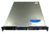
Figure 2. Intel® Server System SR1630HGP Note: Figure 2 is shown with an optional optical drive installed. 2 Intel® Server System SR1630GP / SR1630HGP Service Guide - Intel SR1630HGP | Service Guide - Page 25
supporting one low-profile half-length PCI Express* 2.0 x8 add-in card. Fans Supports two system fans. Video On-board ServerEngines* LLC Pilot II BMC Controller • Integrated 2D Video Controller with 8 MB video memory • 64 MB DDR2 667 MHz memory Intel® Server System SR1630GP / SR1630HGP Service - Intel SR1630HGP | Service Guide - Page 26
(SR1630HGP). Slimline bay for SATA optical drive (optional). Standard front panel One 350-watt power supply module. On-board LLC Pilot II Controller (iBMC) • Integrated Baseboard Management Controller (Integrated BMC), IPMI 2.0 compliant 4 Intel® Server System SR1630GP / SR1630HGP Service Guide - Intel SR1630HGP | Service Guide - Page 27
2. Intel® Server System SR1630GP Control Panel LED Functions LED Color NIC 1 / NIC 2 Activity Green Green Power / Sleep Green Off State On Blink On Off Description NIC Link / AC is on / no access LAN access Power on Power Off / ACPI S4 state Intel® Server System SR1630GP / SR1630HGP Service - Intel SR1630HGP | Service Guide - Page 28
non-recoverable condition. Possible critical power module failure, critical fan failure, voltage (power supply), voltage and thermal fault Non-critical condition POST / system stop. System not ready. HDD access No hard disk drive activity 6 Intel® Server System SR1630GP / SR1630HGP Service Guide - Intel SR1630HGP | Service Guide - Page 29
power) Disk Activity Off N/A Green Off State On Blink On Blink Off N/A Random blink Off Description NIC Link / System is On LAN access Power on Sleep / ACPI S1 state Power Off / ACPI S4 state N/A HDD access No hard disk drive activity Intel® Server System SR1630GP / SR1630HGP Service Guide - Intel SR1630HGP | Service Guide - Page 30
System Rear A. AC Power Connector B. Serial Port A C. Video Connector D. NIC 1 Connector (10/100/1000 MB) E. NIC 2 Connector (10/100/1000 MB) F. USB Ports 6 is selected 100 Mbit / sec data is selected 1000 Mbit / sec data rate is selected 8 Intel® Server System SR1630GP / SR1630HGP Service Guide - Intel SR1630HGP | Service Guide - Page 31
instructions on installing hard drives, see "Installing and Removing a Hard Drive (SR1630GP)" on page 44. Note: Each drive can consume up to 17 W of power. Drives must be specified to run at a maximum ambient temperature of 45 ° C. Note: The Intel® Server System SR1630GP / SR1630HGP does not support - Intel SR1630HGP | Service Guide - Page 32
page x for an Internet link to a list of supported hardware. Intel provides accessory kits for these drives. For installation instructions for an optical drive, see "Installing or Removing a Slimline Optical Drive (SR1630GP)" on page 54. 10 Intel® Server System SR1630GP / SR1630HGP Service Guide - Intel SR1630HGP | Service Guide - Page 33
Air Duct D. PCIe* Riser Assembly E. Processor and Heatsink F. Power Supply G. System Memory DIMM Sockets H. System Blower Fans (two) I. Hard Drive Bays J. Front Panel K. Slimline Optical Drive Bay Figure 6. System Components (SR1630GP) Intel® Server System SR1630GP / SR1630HGP Service Guide 11 - Intel SR1630HGP | Service Guide - Page 34
Server Board F. PCIe* Riser Assembly G. Processor and Heat Sink H. Power Supply I. Front Panel Board J. Front Panel K. Hard Drive Carriers (two) L. Slimline Optical Drive Bay M. Hard Drive Carrier (one) Figure 7. System Components (SR1630HGP) 12 Intel® Server System SR1630GP / SR1630HGP Service - Intel SR1630HGP | Service Guide - Page 35
Server Board Connectors / Components A BCD E F G H I JK L M N DD O CC BB P AA Z V T W U X Y SR Q AF003290 Intel® Server System SR1630GP / SR1630HGP Service Guide 13 - Intel SR1630HGP | Service Guide - Page 36
Video port AA. Six SATA ports M. External serial port BB. Intel USB Connectors N. Main power connector CC. Front panel connector O. CPU power connector DD. Internal serial ports Figure 8. S3420GP Connector and Component Locations 14 Intel® Server System SR1630GP / SR1630HGP Service Guide - Intel SR1630HGP | Service Guide - Page 37
Configuration Jumpers BMC Force Update 2 J1A2 3 Default Enabled ME Force Update 2 J1F1 3 Default Enabled BIOS Recovery 2 J1F3 3 Default Recover Password Clear 2 J1F2 3 Default Password Clear CMOS Clear 2 J1F5 3 Default CLEAR CMOS Intel® Server System SR1630GP / SR1630HGP Service Guide 15 - Intel SR1630HGP | Service Guide - Page 38
in normal position (pins 1-2) allows the system to successfully POST and boot to the operating system environment. BIOS settings are kept intact. Jumper in clear position firmware force update. Figure 9. Configuration Jumper Descriptions 16 Intel® Server System SR1630GP / SR1630HGP Service Guide - Intel SR1630HGP | Service Guide - Page 39
of supported memory DIMMs, see the links under "Server System References" on page x. Table 5. Channel Slot Configuration Channel A Channel B RDIMM A1 A2 A3 B1 B2 B3 X XX XX X X X XX X XX XX XX XX XX XXX XX XXX X Intel® Server System SR1630GP / SR1630HGP Service Guide 17 - Intel SR1630HGP | Service Guide - Page 40
is the default Maximum Performance Mode preferred for Intel® Xeon® processor 3400 based platforms. All three channels may be populated in any Intel® SAS Entry RAID Module option is enabled by default once the Intel® SAS Entry RAID Module. 18 Intel® Server System SR1630GP / SR1630HGP Service Guide - Intel SR1630HGP | Service Guide - Page 41
cannot access the BIOS Setup, you might need to clear the CMOS memory. For instructions on clearing the CMOS, see "Clearing the CMOS" on page 24. Setup Menus Each BIOS Setup menu page any reason, the feature's value field is inaccessible. Intel® Server System SR1630GP / SR1630HGP Service Guide 19 - Intel SR1630HGP | Service Guide - Page 42
"Setup Menu Key Use" describes the keyboard commands you can use in the BIOS Setup menus. Table 6. Setup Menu Key Use Key to Press Description where they were before was pressed without affecting any existing field values. 20 Intel® Server System SR1630GP / SR1630HGP Service Guide - Intel SR1630HGP | Service Guide - Page 43
you see the following message: Press Key if you want to run SETUP 2. Write down the current settings in the BIOS Setup program. Note: Do not skip Step 2. You need these settings to configure your server at the end of the procedure. Intel® Server System SR1630GP / SR1630HGP Service Guide 21 - Intel SR1630HGP | Service Guide - Page 44
the recovery BIOS and flashes the normal BIOS: 1. Power down and unplug the system from the AC power source. 2. Move the recovery jumper at JIF3 from the spare location at pins 2 and 3 to cover pins 1 and 2. Refer to the following figure. 22 Intel® Server System SR1630GP / SR1630HGP Service Guide - Intel SR1630HGP | Service Guide - Page 45
the password clear jumper into the "clear" position clears both passwords. Before a new password(s) is set, you must restore the password clear jumper to its original position. 1. Power down the system and disconnect the AC power. Intel® Server System SR1630GP / SR1630HGP Service Guide 23 - Intel SR1630HGP | Service Guide - Page 46
the AC power. 2. Open the server chassis. For instructions, see your server chassis documentation. 3. Move the jumper from the default operating position (covering pins 1 and 2) to the reset / clear position (covering pins 2 and 3). 24 Intel® Server System SR1630GP / SR1630HGP Service Guide - Intel SR1630HGP | Service Guide - Page 47
device. In the unlikely event the Integrated BMC firmware update process fails (due to the Integrated BMC not being in the proper update state), the server Intel® Server System SR1630GP / SR1630HGP Service Guide 25 - Intel SR1630HGP | Service Guide - Page 48
AC power cord. 8. Open the server chassis. 9. Move jumper from the enabled position (covering pins 2 and 3) to the disabled position (covering pins 1 and 2). 10. Close the server chassis. 11. Reconnect the AC cord and power up the server. 26 Intel® Server System SR1630GP / SR1630HGP Service Guide - Intel SR1630HGP | Service Guide - Page 49
the AC power cord from the system or wall outlet. Note: Some components in the Intel® Server System SR1630HGP are hot-swappable and are noted as such (where applicable) in the following instructions. Note: Most of the illustrations in this chapter show the Intel® Server System SR1630GP with an - Intel SR1630HGP | Service Guide - Page 50
sure you position your bezel as shown. Removing the Front Bezel If your system includes a front bezel, use the following steps. 1. Unlock the bezel. 2. Pull the bezel from the server system. AF003246 Figure 14. Removing the Front Bezel 28 Intel® Server System SR1630GP / SR1630HGP Service Guide - Intel SR1630HGP | Service Guide - Page 51
the bezel, line up the center notch on the bezel with the center guide on the rack handles. 2. Push the bezel onto the front of the server system until it clicks into place. 3. Lock the bezel. AF003247 Figure 15. Installing the Front Bezel Intel® Server System SR1630GP / SR1630HGP Service Guide 29 - Intel SR1630HGP | Service Guide - Page 52
on the blue grip point at the front of the server. Slide the cover back until it stops and then lift the cover upward to remove it. See letter "C" in Figure 16. B C A AF000662 Figure 16. Removing the Server System Cover (SR1630GP) 30 Intel® Server System SR1630GP / SR1630HGP Service Guide - Intel SR1630HGP | Service Guide - Page 53
rearward on the blue grip point at the front of the server. Slide the cover back until it stops and then lift the cover upward to remove it. See letter "B" in Figure 17. B A AF001578 Figure 17. Removing the Server System Cover (SR1630HGP) Intel® Server System SR1630GP / SR1630HGP Service Guide 31 - Intel SR1630HGP | Service Guide - Page 54
server system so the side edges of the cover sit just inside the server system sidewalls. Slide the cover forward. See letter "A" in Figure 19. 6. SR1630HGP: Install the four screws at the front of the server. See letter "B" in Figure 19. 32 Intel® Server System SR1630GP / SR1630HGP Service Guide - Intel SR1630HGP | Service Guide - Page 55
power cable. 3. Remove the server system cover. For instructions, see "Removing the Server System Cover". 4. Lift the processor air duct from its location behind the two system blower fans (see Figure 20 for SR1630GP; see Figure 21 for SR1630HGP). Intel® Server System SR1630GP / SR1630HGP Service - Intel SR1630HGP | Service Guide - Page 56
AF003248 Figure 20. Removing the Processor Air Duct (SR1630GP) AF003249 Figure 21. Removing the Processor Air Duct (SR1630HGP) 34 Intel® Server System SR1630GP / SR1630HGP Service Guide - Intel SR1630HGP | Service Guide - Page 57
not to pinch or disengage cables that may be near or under the air duct. 5. Install the server system cover. For instructions, see "Installing the Server System Cover". AF003250 Figure 22. Installing the Processor Air Duct (SR1630GP) Intel® Server System SR1630GP / SR1630HGP Service Guide 35 - Intel SR1630HGP | Service Guide - Page 58
DIMM A1, DIMM A2, DIMM B1, and DIMM B2 starting from the center of the board. See "Memory" on page 14 for a discussion of the memory requirements and options. See "Server System References" on page x for a link to the list of tested DIMMs. 36 Intel® Server System SR1630GP / SR1630HGP Service Guide - Intel SR1630HGP | Service Guide - Page 59
the server system cover. For instructions, see "Installing the Server System Cover". Removing DIMMs To remove a DIMM, follow these steps: 1. Observe the safety and ESD precautions at the beginning of this book. See "Safety Information" on page iii. Intel® Server System SR1630GP / SR1630HGP Service - Intel SR1630HGP | Service Guide - Page 60
peripheral devices and the AC power cable. 3. Remove the server system cover. For instructions, see "Removing the Server System Cover" on page 30. Install the server system cover. For instructions, see "Installing the Server System Cover". 38 Intel® Server System SR1630GP / SR1630HGP Service Guide - Intel SR1630HGP | Service Guide - Page 61
load plate. 9. Remove the processor. 10. If installing a replacement processor, see "Installing the Processor" on page 40. Otherwise, install the protective socket cover over the empty processor socket and then reinstall the chassis cover. Intel® Server System SR1630GP / SR1630HGP Service Guide 39 - Intel SR1630HGP | Service Guide - Page 62
Figure 25. REMOVE A B AF003186 Figure 25. Lifting the Processor Socket Handle 5. Push the rear tab with your finger to slightly lift the front of the load plate. Raise the load plate completely. Raise the CPU load plate (see Figure 26). 40 Intel® Server System SR1630GP / SR1630HGP Service Guide - Intel SR1630HGP | Service Guide - Page 63
Caution: Do not touch the socket pins; they are very sensitive and easily damaged. 6. Remove the processor from the packaging box and remove the protective shipping cover. See Figure 27. A AF003189 Figure 27. Removing the Shipping Cover Intel® Server System SR1630GP / SR1630HGP Service Guide 41 - Intel SR1630HGP | Service Guide - Page 64
. 9. Remove the protective socket cover. See Figure 29. Figure 29. Removing the Protective Socket Cover Note: Retain the protective socket cover for use when removing a processor that will not be replaced. 42 Intel® Server System SR1630GP / SR1630HGP Service Guide - Intel SR1630HGP | Service Guide - Page 65
Heat Sink Before installing the heat sink, you must install your processor. For instructions, see "Installing the Processor" on page 40. Caution: The heat sink has Thermal 1 4 FCrohnatssis AF001049 Figure 30. Installing the Heat Sink Intel® Server System SR1630GP / SR1630HGP Service Guide 43 - Intel SR1630HGP | Service Guide - Page 66
2. Power down the server. Unplug all peripheral devices and the AC power cable. 3. Remove the server system cover. For instructions, see "Removing the Server System Cover" on page 30. 4. Locate the drive position you want to use. See Figure 31. 44 Intel® Server System SR1630GP / SR1630HGP Service - Intel SR1630HGP | Service Guide - Page 67
1 AF003252 Figure 31. Locating Drive Positions (SR1630GP) 5. HDD1 location only: Slide the power cables from the cable clip located on the B ChFarsosnist AF001050 Figure 32. Removing Drive Carrier from the Server System (SR1630GP) Intel® Server System SR1630GP / SR1630HGP Service Guide 45 - Intel SR1630HGP | Service Guide - Page 68
shown by the letter "A" in the figure. The data and power connectors must be positioned so they are accessible through the cut-out system. C A HDD 0 B HDD 1 AF003253 Figure 34. Install Drive Assembly into the Server System (SR1630GP) 46 Intel® Server System SR1630GP / SR1630HGP Service Guide - Intel SR1630HGP | Service Guide - Page 69
power supply to the HDD1 connector. See letter "D" in Figure 35. - Letter "B": If a drive is installed in the HDD0 carrier, attach the middle connector on the daisy chain power cable to the HDD0 power connector. See letter "D" in Figure 35. Intel® Server System SR1630GP / SR1630HGP Service Guide - Intel SR1630HGP | Service Guide - Page 70
of this book. See "Safety Information" on page iii. 2. Power down the server and unplug all peripheral devices and the AC power cable. 3. Remove the server system cover. For instructions, see "Removing the Server System Cover" on page 30. 48 Intel® Server System SR1630GP / SR1630HGP Service Guide - Intel SR1630HGP | Service Guide - Page 71
drive. 5. HDD1 location only: Slide the power cable from the cable clip located on SR1630GP)" on page 44, beginning with step 8. 10. Insert the screws that held the drive in the carrier into the screw locations on the carrier for future use. Intel® Server System SR1630GP / SR1630HGP Service Guide - Intel SR1630HGP | Service Guide - Page 72
screw that you removed in Step 6. Note: You must install the assembly that contains the optical drive bracket at the left side of the system. 13. Install the server system cover. For instructions, see "Installing the Server System Cover". 50 Intel® Server System SR1630GP / SR1630HGP Service Guide - Intel SR1630HGP | Service Guide - Page 73
) 1. If it is installed, remove the front bezel. For instructions, see "Removing the Front Bezel". 2. Locate the drive position you want to use. See Figure 37. HDD 0 HDD 1 HDD 2 AF003255 Figure 37. Locating Drive Positions (SR1630HGP) Intel® Server System SR1630GP / SR1630HGP Service Guide 51 - Intel SR1630HGP | Service Guide - Page 74
. 7. Set any jumpers and/or switches on the drive according to the drive manufacturer's instructions. 8. With the drive circuit-side down, position the connector end of the drive so 39. Installing Drive into Drive Carrier (SR1630HGP) 52 Intel® Server System SR1630GP / SR1630HGP Service Guide - Intel SR1630HGP | Service Guide - Page 75
the carrier for future use. 7. With the black lever in the fully open position, slide the drive carrier into the server system. The green latch must be to the right. Do not push on the black lever until the lever begins to close by itself. Intel® Server System SR1630GP / SR1630HGP Service Guide 53 - Intel SR1630HGP | Service Guide - Page 76
installed, remove the bezel. For instructions, see "Removing the Front Bezel" on page 28. 5. First time installation only: Remove the knock-out by rocking it back and forth. See letter "A" in Figure 41. You cannot reinstall the knock-out. 54 Intel® Server System SR1630GP / SR1630HGP Service Guide - Intel SR1630HGP | Service Guide - Page 77
by letter "A in Figure 43. 8. Reinstall the screw that you removed in Step 5. 9. Connect the mini SATA power connector on the optical drive. 10. Connect the data cable to the optical drive and to the SATA connector on the server board. Intel® Server System SR1630GP / SR1630HGP Service Guide 55 - Intel SR1630HGP | Service Guide - Page 78
the screw that holds the optical drive bracket to the server chassis. See letter "C" in Figure 44. Save this screw. You will reinstall it later. 7. Slide the optical drive out through the front of the system. See letter "D" in Figure 44. 56 Intel® Server System SR1630GP / SR1630HGP Service Guide - Intel SR1630HGP | Service Guide - Page 79
10. Store the brackets for future use. 11. (Optional) Install the front bezel. For instructions, see "Installing the Front Bezel" on page 29. 12. Install the server system cover. For instructions, see "Installing the Server System Cover". Intel® Server System SR1630GP / SR1630HGP Service Guide 57 - Intel SR1630HGP | Service Guide - Page 80
page iii. 2. Power down the server and unplug all peripheral devices and the AC power cable. 3. Remove the server system cover. For instructions, see "Removing the Server System Cover" on page 30 the Optical Drive to the Attachment Bracket 58 Intel® Server System SR1630GP / SR1630HGP Service Guide - Intel SR1630HGP | Service Guide - Page 81
instructions, see "Removing the Front Bezel" on page 28. 5. Remove the screws holding the drive in place (see letters "A" and "B" in Figure 48) and slide the optical drive assembly out through the front of the chassis (see letter "C" in Figure 48). Intel® Server System SR1630GP / SR1630HGP Service - Intel SR1630HGP | Service Guide - Page 82
Optical Drive from the Attachment Bracket 7. (Optional) Install the front bezel. For instructions, see "Installing the Front Bezel" on page 29. 8. Install the server system cover. For instructions, see "Installing the Server System Cover". 60 Intel® Server System SR1630GP / SR1630HGP Service Guide - Intel SR1630HGP | Service Guide - Page 83
iii. 2. Power down the server and unplug all peripheral devices and the AC power cable. 3. Remove the server system cover. For instructions, see "Removing the Server System Cover" on . Removing PCIe* Riser Assembly from the Server System Intel® Server System SR1630GP / SR1630HGP Service Guide 61 - Intel SR1630HGP | Service Guide - Page 84
Riser Assembly into the Server System 3. Press down uniformly until the two hooks on the rear of the PCIe* riser assembly engage the server system back panel slots. The riser cards will seat into the matching sockets on the server board. 62 Intel® Server System SR1630GP / SR1630HGP Service Guide - Intel SR1630HGP | Service Guide - Page 85
For instructions, see "Removing a PCI Add-in Card" on page 66. 7. Remove the two screws that attach the riser card to the riser assembly. See Figure 52. Save these screws to be used later. AF003288 Figure 52. Removing Riser Card from Riser Assembly Intel® Server System SR1630GP / SR1630HGP Service - Intel SR1630HGP | Service Guide - Page 86
cables to add-in cards that require them. See your add-in card documentation for information and add-in card requirements. 11. Re-install the processor air duct. For instructions, see "Installing the Processor Air Duct" on page 35. 64 Intel® Server System SR1630GP / SR1630HGP Service Guide - Intel SR1630HGP | Service Guide - Page 87
and the AC power cable. 3. Remove the server system cover. For instructions, see "Removing the Server System Cover" on page 30. 4. Remove the PCIe* Riser assembly. For instructions, see "Removing the PCIe* Riser Assembly" on page 61. Intel® Server System SR1630GP / SR1630HGP Service Guide 65 - Intel SR1630HGP | Service Guide - Page 88
and the AC power cable. 3. Remove the server system cover. For instructions, see "Removing the Server System Cover" on page 30. 4. Remove the PCIe* Riser assembly. For instructions, see "Removing the PCIe* Riser Assembly" on page 61. 66 Intel® Server System SR1630GP / SR1630HGP Service Guide - Intel SR1630HGP | Service Guide - Page 89
For instructions, see "Installing the Processor Air Duct" on page 35. 11. Install the server system cover. For instructions, see "Installing the Server System Cover". 12. Plug all peripheral devices and the AC power cable into the server. Intel® Server System SR1630GP / SR1630HGP Service Guide 67 - Intel SR1630HGP | Service Guide - Page 90
6. Detach all cables connected to the server board. 7. Remove the heat sink and the processor. For instructions, see "Removing the Heat Sink and Processor" on page 39. 8. Remove the DIMMs. For instructions, see "Removing DIMMs" on page 37. 68 Intel® Server System SR1630GP / SR1630HGP Service Guide - Intel SR1630HGP | Service Guide - Page 91
PCIe* Riser Assembly" on page 62. 14. Reconnect all cables to the server board. For a full cabling diagram, see Figure 80 on page 88. 15. Install the processor air duct. For instructions, see "Installing the Processor Air Duct" on page 35. Intel® Server System SR1630GP / SR1630HGP Service Guide 69 - Intel SR1630HGP | Service Guide - Page 92
assembly. For instructions, see "Removing the PCIe* Riser Assembly" on page 61. 6. Place the server board into the server system as shown by letter "A" in Figure 57. 7. Attach the server board with nine screws. See letter "B" in Figure 57. 70 Intel® Server System SR1630GP / SR1630HGP Service Guide - Intel SR1630HGP | Service Guide - Page 93
B A AF003262 Figure 57. Installing the Server Board Intel® Server System SR1630GP / SR1630HGP Service Guide 71 - Intel SR1630HGP | Service Guide - Page 94
enligt fabrikantens instruktion. Varoitus: Paristo voi räjähtää, jos se on virheellisesti asennettu. Vaihda paristo ainoastaan laitevalmistajan suosittelemaan tyyppiin. Hävitä käytetty paristo valmistajan ohjeiden mukaisesti. 72 Intel® Server System SR1630GP / SR1630HGP Service Guide - Intel SR1630HGP | Service Guide - Page 95
lithium battery from its package, and, being careful to observe the correct polarity, insert it in the battery socket. 9. Close the chassis. 10. Run the BIOS Setup utility to restore the configuration settings. Intel® Server System SR1630GP / SR1630HGP Service Guide 73 - Intel SR1630HGP | Service Guide - Page 96
- B: 2x12 main power connector - C: Daisy-chain cable to: ✧ Optical drive power connector, if an optical drive is installed ✧ HDD0 power connector, if a hard drive is installed here ✧ HDD1 power connector, if a hard drive is installed here 74 Intel® Server System SR1630GP / SR1630HGP Service Guide - Intel SR1630HGP | Service Guide - Page 97
. A B E D C AF003263 Figure 59. Disconnecting Power Cables (SR1630GP) Intel® Server System SR1630GP / SR1630HGP Service Guide 75 - Intel SR1630HGP | Service Guide - Page 98
the foot at the bottom of the chassis. See letter "B" in Figure 60. 7. Slide the power supply forward (see letter "C") and then lift it from the chassis. A B C B AF003264 Figure 60. Removing Power Supply from the Server System (SR1630GP) 76 Intel® Server System SR1630GP / SR1630HGP Service Guide - Intel SR1630HGP | Service Guide - Page 99
"B" in Figure 61. 10. Insert the screw you removed in Step 5 to attach the power supply to the server system. See letter "C" in Figure 61. C B A B AF003265 Figure 61. Installing Power Supply Module into the Server System (SR1630GP) Intel® Server System SR1630GP / SR1630HGP Service Guide 77 - Intel SR1630HGP | Service Guide - Page 100
power supply. . A B E D C AF003266 Figure 62. Connecting Power Cables (SR1630GP) 12. Install the server system cover. For instructions, see "Installing the Server System Cover". 13. Plug all peripheral devices and the AC power cable into the server. 78 Intel® Server System SR1630GP / SR1630HGP - Intel SR1630HGP | Service Guide - Page 101
bottom of the chassis (see letter "B" in Figure 63). 6. Slide the power supply forward (see letter "C" in Figure 63) and then lift it from the chassis. A C B B AF003267 Figure 63. Removing Power Supply from the Server System (SR1630HGP) Intel® Server System SR1630GP / SR1630HGP Service Guide 79 - Intel SR1630HGP | Service Guide - Page 102
to the server board and peripherals. 10. Install the server system cover. For instructions, see "Installing the Server System Cover". 11. Plug all peripheral devices and the AC power cable into the server (see letter "C" in Figure 64). 80 Intel® Server System SR1630GP / SR1630HGP Service Guide - Intel SR1630HGP | Service Guide - Page 103
"D" in Figure 65. Save these screws. You will re-install them later. 7. Lift the front panel board from the system. See letter "E" in Figure 65. A B C D E AF003269 Figure 65. Removing Front Panel Board from the Server System (SR1630GP) Intel® Server System SR1630GP / SR1630HGP Service Guide 81 - Intel SR1630HGP | Service Guide - Page 104
66. Installing Front Panel Board into the Server System (SR1630GP) 13. Install the server system cover. For instructions, see "Installing the Server System Cover". 14. Plug all peripheral devices and the AC power cable into the server. 82 Intel® Server System SR1630GP / SR1630HGP Service Guide - Intel SR1630HGP | Service Guide - Page 105
later. 6. Slide the front panel board back (see letter "B" in Figure 67) and lift the front panel board from the system (see letter "C" in Figure 67). A B C AF003271 Figure 67. Removing Front Panel Board from the Server System (SR1630HGP) Intel® Server System SR1630GP / SR1630HGP Service Guide 83 - Intel SR1630HGP | Service Guide - Page 106
the board clicks into place (see letter "B" in Figure 69). 9. Use the screw you removed in Step 5 to attach the front panel board to the system (see letter "C" in Figure 69). 84 Intel® Server System SR1630GP / SR1630HGP Service Guide - Intel SR1630HGP | Service Guide - Page 107
C B A AF003273 Figure 69. Installing Front Panel Board into the Server System (SR1630HGP) Intel® Server System SR1630GP / SR1630HGP Service Guide 85 - Intel SR1630HGP | Service Guide - Page 108
cable if you removed it in Step 4. 12. Connect the front panel cable. 13. Install the server system cover. For instructions, see "Installing the Server System Cover". 14. Plug all peripheral devices and the AC power cable into the server. 86 Intel® Server System SR1630GP / SR1630HGP Service Guide - Intel SR1630HGP | Service Guide - Page 109
For instructions, see "Removing the Processor Air Duct" on page 33. 5. Disconnect the two fan cables from the server board (see letter "B" in Figure 71) and untie the cable tie (see letter "C" in Figure 71). A B C AF003275 Figure 71. Disconnecting System Blower Fans (SR1630GP) Intel® Server System - Intel SR1630HGP | Service Guide - Page 110
from the server. Lift the bracket at an angle, front of the bracket first, to clear the hard disk drive brackets. See letter "C" in Figure 72. A B C AF003276 Figure 72. Removing Bracket and System Blower Fans from Server System (SR1630GP) 88 Intel® Server System SR1630GP / SR1630HGP Service Guide - Intel SR1630HGP | Service Guide - Page 111
bracket. See letter "B" in Figure 73. B A AF000963 Figure 73. Removing Fan from Fan Bracket (SR1630GP) 11. Install the replacement fan onto the bracket, using the two screws you removed in Step 9. 12. Set at the front of the fan bracket. Intel® Server System SR1630GP / SR1630HGP Service Guide 89 - Intel SR1630HGP | Service Guide - Page 112
the fans to the server board. See letters "A" and "B" in Figure 74. B A AF003277 Figure 74. Connecting System Blower Fans (SR1630GP) 15. Install the processor air duct. For instructions. see "Installing the Processor Air Duct" on page 35. 90 Intel® Server System SR1630GP / SR1630HGP Service Guide - Intel SR1630HGP | Service Guide - Page 113
instructions, see "Removing the Processor Air Duct" on page 33. 5. Remove the two screws that hold the fan in place. Save these screws. You will re- install them later. 6. Disconnect the fan cable from the server board (see letter "B" in Figure 75). Intel® Server System SR1630GP / SR1630HGP Service - Intel SR1630HGP | Service Guide - Page 114
fan into the chassis (see letter "A" in Figure 76), using the two screws you removed previously. 9. Connect the fan cable to the server board (see letter "B" in Figure 76). 10. Install the processor air duct (see letter "C" in Figure 76). 92 Intel® Server System SR1630GP / SR1630HGP Service Guide - Intel SR1630HGP | Service Guide - Page 115
and the AC power cable. 3. If it is installed, remove the front bezel if it is installed. For instructions, see "Removing the Front Bezel" on page 28. 4. Attach the rack handle to the server system with two screws as shown in Figure 77. Intel® Server System SR1630GP / SR1630HGP Service Guide 93 - Intel SR1630HGP | Service Guide - Page 116
5. Repeat Step 4 on the opposite side of the server. 6. (Optional) Install the front bezel, if desired. For instructions, see "Installing the Front Bezel" on page 29. 7. Plug all peripheral devices and the AC power cable into the server. 94 Intel® Server System SR1630GP / SR1630HGP Service Guide - Intel SR1630HGP | Service Guide - Page 117
Rack Handle 5. Repeat Step 4 on the opposite side of the system. 6. (Optional) Install the front bezel, if desired. For instructions, see "Installing the Front Bezel" on page 29. 7. Plug all peripheral devices and the AC power cable into the server. Intel® Server System SR1630GP / SR1630HGP Service - Intel SR1630HGP | Service Guide - Page 118
96 Intel® Server System SR1630GP / SR1630HGP Service Guide - Intel SR1630HGP | Service Guide - Page 119
. For readability, separate figures for power cable routing and data cable routing are included. Make sure all necessary power and data cables are connected and where it connects to the server board and at the PCI cooling fan itself. Intel® Server System SR1630GP / SR1630HGP Service Guide 97 - Intel SR1630HGP | Service Guide - Page 120
. To make Figure 79 more clear, where the connectors attach to the components, the labels "F1", "F2", and "F3" are used. The end at the power supply itself is labeled "F". 98 Intel® Server System SR1630GP / SR1630HGP Service Guide - Intel SR1630HGP | Service Guide - Page 121
to Server Board SATA 3 L Link to backplane SPGIO M Optical Drive to Power Supply Server Board SATA Connector Legend 5 Begin cable connections at 2 the SATA-0 location. 1 4 0 3 AF003282 Figure 80. Data Cable Routing (SR1630HGP) Intel® Server System SR1630GP / SR1630HGP Service Guide 99 - Intel SR1630HGP | Service Guide - Page 122
Data to Server Board SATA 3 L Link to backplane SPGIO M Optical Drive to Power Supply Server Board SATA Connector Legend 5 Begin cable connections at 2 the SATA-0 location. 1 4 0 3 AF003282 Figure 81. Cable Routing (SR1630HGP) 100 Intel® Server System SR1630GP / SR1630HGP Service Guide - Intel SR1630HGP | Service Guide - Page 123
24 A 0.3 A Maximum Current Warning: Do not exceed a combined power output of 90 W for the +5 V and +3.3 V outputs. Exceeding a combined 90 W will overload the power subsystem and may cause the power supplies to overheat and malfunction. Intel® Server System SR1630GP / SR1630HGP Service Guide 101 - Intel SR1630HGP | Service Guide - Page 124
. 7 Bels in sound power for a typical office ambient temperature (65 to 75 °F). Your selection of peripherals may change the noise level. Tested to 8 Kilovotls (KV) contact discharge, 12 kilovolts (KV) air discharge; no component damage. 102 Intel® Server System SR1630GP / SR1630HGP Service Guide - Intel SR1630HGP | Service Guide - Page 125
system memory, restarts POST, reloads the operating system, and halts power to all peripherals Reset the BMC and get it back to a stable state Press Reset button Power off/on button Remove AC power from the server for one minute Intel® Server System SR1630GP / SR1630HGP Service - Intel SR1630HGP | Service Guide - Page 126
components from the tested components lists? Check the tested memory and chassis lists, as well as the supported hardware and operating system list. See "Server System References" on page x for links to the tested component lists. 104 Intel® Server System SR1630GP / SR1630HGP Service Guide - Intel SR1630HGP | Service Guide - Page 127
supplied with your video display monitor). 4. If the operating system Problems and Corrective Actions This section provides possible solutions for these specific problems: • Power light does not light. • No characters appear on screen. Intel® Server System SR1630GP / SR1630HGP Service Guide - Intel SR1630HGP | Service Guide - Page 128
on the bottom of the server board and cause a short. No Characters Appear on Screen Check the following: • Is the keyboard functioning? Test it by turning the "Num Lock" function on and off to make sure the Num Lock light is functioning. 106 Intel® Server System SR1630GP / SR1630HGP Service Guide - Intel SR1630HGP | Service Guide - Page 129
? • Does this video monitor work correctly if plugged into a different system? System Cooling Fans Do Not Rotate Properly If the system cooling fans are not operating properly, it is an indication of possible system component failure. Intel® Server System SR1630GP / SR1630HGP Service Guide 107 - Intel SR1630HGP | Service Guide - Page 130
attached to the correct connector at the system back panel. • Try a different network cable. • Make sure you are using the correct and the current drivers. See "Server System References" on page x for a link to the current drivers. 108 Intel® Server System SR1630GP / SR1630HGP Service Guide - Intel SR1630HGP | Service Guide - Page 131
. • Try reseating the add-in adapter. The add-in adapter stopped working without apparent cause • Reseat the adapter. • The network driver files may be corrupt or deleted. Delete and then reinstall the drivers. • Run diagnostics. Intel® Server System SR1630GP / SR1630HGP Service Guide 109 - Intel SR1630HGP | Service Guide - Page 132
incorrect), a marginal power supply, or other random component failures. • If you suspect a transient voltage spike, power outage, or brownout might have occurred, reload the software and try running it again. Symptoms of voltage spikes 110 Intel® Server System SR1630GP / SR1630HGP Service Guide - Intel SR1630HGP | Service Guide - Page 133
a RAID configuration with SCSI or SATA drives, make sure the RAID card is installed correctly. Bootable CD-ROM Disk Is Not Detected Check the following: • Make sure the BIOS is configured to allow the CD-ROM to be the first bootable device. Intel® Server System SR1630GP / SR1630HGP Service Guide - Intel SR1630HGP | Service Guide - Page 134
. Please note that not all error conditions are supported by BIOS beep codes. Table 11. POST Error Beep Codes Number of Beeps 3 Reason for Beeps and Action to Take System halted because a fatal error related to the memory was detected. 112 Intel® Server System SR1630GP / SR1630HGP Service Guide - Intel SR1630HGP | Service Guide - Page 135
electrostatic discharge (ESD) protection by wearing an antistatic wrist strap attached to chassis ground of the system-any unpainted metal surface-when handling components. 6. Do not operate the system with the chassis covers removed. Intel® Server System SR1630GP / SR1630HGP Service Guide 113 - Intel SR1630HGP | Service Guide - Page 136
system to prevent unauthorized access inside the system. 5. Connect all external cables and the AC power cord(s) to the system. A microprocessor and heat sink may be hot if the system batteries according to manufacturer's instructions. 114 Intel® Server System SR1630GP / SR1630HGP Service Guide - Intel SR1630HGP | Service Guide - Page 137
Netzkabel. Der Wechselstrom des Systems wird durch den Ein-/Aus-Schalter für Gleichstrom nicht ausgeschaltet. Ziehen Sie jedes Wechselstrom-Netzkabel aus der Steckdose bzw. dem Netzgerät, um den Stromanschluß des Systems zu unterbrechen. Intel® Server System SR1630GP / SR1630HGP Service Guide 115 - Intel SR1630HGP | Service Guide - Page 138
an. 4. Bringen Sie die Verschlußeinrichtung (Padlock) wieder an und schließen Sie diese, um ein unerlaubtes Öffnen des Systems zu verhindern. 5. Schließen Sie alle externen Kabel und den AC Stromanschlußstecker Ihres Systems wieder an. 116 Intel® Server System SR1630GP / SR1630HGP Service Guide - Intel SR1630HGP | Service Guide - Page 139
Entsorgen Sie verbrauchte Batterien den Anweisungen des Herstellers entsprechend. Das System wurde für den Betrieb in einer normalen Büroumgebung entwickelt. Der alimentation. Veuillez contacter un technicien qualifié en cas de problème. Intel® Server System SR1630GP / SR1630HGP Service Guide 117 - Intel SR1630HGP | Service Guide - Page 140
ère du système, déverrouillez-le et retirez-le. 2. Retirez toutes les vis des panneaux et mettez-les dans un endroit sûr. 3. Retirez les panneaux. 118 Intel® Server System SR1630GP / SR1630HGP Service Guide - Intel SR1630HGP | Service Guide - Page 141
ou d'un type équivalent recommandé par le fabricant. Disposez des piles usées selon les instructions du fabricant. Le système a été conçu pour fonctionner dans un cadre de travail normal. le seul moyen de mettre le système hors tension). Intel® Server System SR1630GP / SR1630HGP Service Guide 119 - Intel SR1630HGP | Service Guide - Page 142
del chasis - o a cualquier tipo de superficie de metal sin pintar. 6. No ponga en marcha el sistema si se han extraído las tapas del chasis. Intel® Server System SR1630GP / SR1630HGP Service Guide - Intel SR1630HGP | Service Guide - Page 143
pilas iguales o del mismo tipo que las recomendadas por el fabricante del equipo. Para deshacerse de las pilas usadas, siga igualmente las instrucciones del fabricante. Intel® Server System SR1630GP / SR1630HGP Service Guide 121 - Intel SR1630HGP | Service Guide - Page 144
correctamente instalada. • "Provisto de espacio suficiente como para acceder a los cables de alimentación, ya que éstos hacen de medio principal de desconexión del sistema. 122 Intel® Server System SR1630GP / SR1630HGP Service Guide - Intel SR1630HGP | Service Guide - Page 145
lucchetto dal retro del sistema qualora ve ne fosse uno installato. 2. Togliere e mettere in un posto sicuro tutte le viti delle coperture. 3. Togliere le coperture. Intel® Server System SR1630GP / SR1630HGP Service Guide 123 - Intel SR1630HGP | Service Guide - Page 146
una presa a muro correttamente installata. • "Dotata di spazio sufficiente ad accedere ai cavi di alimentazione, i quali rappresentano il mezzo principale di scollegamento del sistema. 124 Intel® Server System SR1630GP / SR1630HGP Service Guide - Intel SR1630HGP | Service Guide - Page 147
server should be integrated and serviced only by technically qualified persons. You must adhere to the guidelines in this guide and the assembly instructions in your server manuals injury or death if safety instructions are not followed. Intel® Server System SR1630GP / SR1630HGP Service Guide 125 - Intel SR1630HGP | Service Guide - Page 148
grounded wall outlet. • Provided with sufficient space to access the power supply cord(s), because they serve as the product's main power disconnect. Equipment Handling Practices Reduce the risk of personal injury or equipment damage: 126 Intel® Server System SR1630GP / SR1630HGP Service Guide - Intel SR1630HGP | Service Guide - Page 149
to the compute module. • Retain all screws or other fasteners when removing access cover(s). Upon completion of accessing inside the product, refasten access cover with original screws or fasteners. Intel® Server System SR1630GP / SR1630HGP Service Guide 127 - Intel SR1630HGP | Service Guide - Page 150
. Do not attempt to disassemble, puncture, or otherwise damage a battery. Cooling and Airflow Caution: Carefully route cables as directed to minimize airflow blockage and cooling problems. 128 Intel® Server System SR1630GP / SR1630HGP Service Guide - Intel SR1630HGP | Service Guide - Page 151
the product instructions. Laser Peripherals serviceable • Return to manufacturer for servicing Deutsch Sicherheitshinweise für den Server Das vorliegende Dokument bezieht sich auf Intel®Serverplatinen, Intel®Servergehäuse (Standfuß und Rack Intel® Server System SR1630GP / SR1630HGP Service Guide 129 - Intel SR1630HGP | Service Guide - Page 152
öffentlichen Räumlichkeiten installiert werden kann. Die Eignung dieses Produkts für andere Einsatzbereiche als IT (z. B. Medizin, Industrie, Alarmsysteme oder Prüfgeräte) kann u. U. weitere Tests erfordern. 130 Intel® Server System SR1630GP / SR1630HGP Service Guide - Intel SR1630HGP | Service Guide - Page 153
äte erzeugt werden. • In gewittergefährdeten Gebieten sollten Sie das System an einen Überspannungsschutz anschließen und bei einem Gewitter die Telekommunikationskabel , um das Gewicht zu reduzieren und die Handhabung zu erleichtern. Intel® Server System SR1630GP / SR1630HGP Service Guide 131 - Intel SR1630HGP | Service Guide - Page 154
Arbeiten im Netzteil aus. Das Netzteil enthält keine für den Benutzer wartungsbedürftigen Teile. Schicken Sie das Gerät für Wartungsarbeiten an den Hersteller zurück. 132 Intel® Server System SR1630GP / SR1630HGP Service Guide - Intel SR1630HGP | Service Guide - Page 155
.Verwenden Sie dazu, sofern verfügbar, eine leitfahige Schaumstoffunterlage, aber niche die Schutzhülle der Platine. Ziehen Sie die Platine nicht über eine Fläche. Intel® Server System SR1630GP / SR1630HGP Service Guide 133 - Intel SR1630HGP | Service Guide - Page 156
Laser- Komponenten. • Laser-Peripheriegeräte oder -Komponenten besitzen keine für den Benutzer wartungsbedürftigen Teile. • Schicken Sie das Gerät für Wartungsarbeiten an den Hersteller zurück. 134 Intel® Server System SR1630GP / SR1630HGP Service Guide - Intel SR1630HGP | Service Guide - Page 157
Ce document s'applique aux cartes serveur Intel®, au châssis de serveur Intel®(sur pieds et sur rack) et aux périphériques installés. Vous devez suivre les informations de ce guide et les instructions d'assemblage des manuels de serveur pour Intel® Server System SR1630GP / SR1630HGP Service Guide 135 - Intel SR1630HGP | Service Guide - Page 158
à un suppresseur de surtension et de déconnecter les lignes de télécommunication de votre modem pendant les orages. • Équipé d'une prise murale reliée à la terre. 136 Intel® Server System SR1630GP / SR1630HGP Service Guide - Intel SR1630HGP | Service Guide - Page 159
autre assistance appropriée lorsque vous déplacez et soulevez le matériel. • Pour réduire le poids en vue de faciliter la manipulation, retirez tout composant amovible. Intel® Server System SR1630GP / SR1630HGP Service Guide 137 - Intel SR1630HGP | Service Guide - Page 160
d'accéder à l'intérieur du produit, refixez le panneau d'accès avec les vis ou attaches d'origine. • N'essayez pas d'accéder à l'intérieur du bloc d'alimentation. Il ne contient aucune piè remplacement avant de retirer le bloc du serveur. 138 Intel® Server System SR1630GP / SR1630HGP Service Guide - Intel SR1630HGP | Service Guide - Page 161
les panneaux du châssis sont en place. L'utilisation du système sans les panneaux peut endommager les composants système. Pour installer les panneaux : Intel® Server System SR1630GP / SR1630HGP Service Guide 139 - Intel SR1630HGP | Service Guide - Page 162
au châssis en suivant les instructions du produit. Périphériques laser tarjetas de servidor de Intel®, los gabinetes de servidor de Intel® (montaje en rack y en pedestal) instrucciones de montaje de los manuales del servidor para asegurar y Intel® Server System SR1630GP / SR1630HGP Service Guide - Intel SR1630HGP | Service Guide - Page 163
para otras categorías de productos y entornos además de las aplicaciones informáticas (por ejemplo, soluciones médicas, industriales, residenciales, sistemas de alarma y equipos de pruebas). Intel® Server System SR1630GP / SR1630HGP Service Guide 141 - Intel SR1630HGP | Service Guide - Page 164
cualquier componente que no es de conexión en funcionamiento. Algunas fuentes de alimentación de electricidad de los servidores de Intel utilizan el polo neutral del fuselaje. Para evitar riesgos de choques eléctricos use precauciones al 142 Intel® Server System SR1630GP / SR1630HGP Service Guide - Intel SR1630HGP | Service Guide - Page 165
que el sistema se enfríe antes de abrir las cubiertas. Para que no llegue a tocar los componentes que estén calientes cuando esté realizando una instalación Intel® Server System SR1630GP / SR1630HGP Service Guide 143 - Intel SR1630HGP | Service Guide - Page 166
cubiertas: • Compruebe primero que no ha dejado herramientas o piezas sueltas dentro del sistema. • Compruebe que los cables, tarjetas adicionales y otros componentes están instalados correctamente. 144 Intel® Server System SR1630GP / SR1630HGP Service Guide - Intel SR1630HGP | Service Guide - Page 167
caja de ningún periférico o dispositivo láser • Los periféricos o dispositivos láser no pueden ser reparados por el usuario • Haga que el fabricante los repare. Intel® Server System SR1630GP / SR1630HGP Service Guide 145 - Intel SR1630HGP | Service Guide - Page 168
简体中文 Intel Intel Intel Web UL 注意 警告 146 Intel® Server System SR1630GP / SR1630HGP Service Guide - Intel SR1630HGP | Service Guide - Page 169
Intel® Server System SR1630GP / SR1630HGP Service Guide 147 - Intel SR1630HGP | Service Guide - Page 170
ITE ITE 场地选择 5V 148 Intel® Server System SR1630GP / SR1630HGP Service Guide - Intel SR1630HGP | Service Guide - Page 171
Intel® Server System SR1630GP / SR1630HGP Service Guide 149 - Intel SR1630HGP | Service Guide - Page 172
ESD) ESD ESD ESD ESD 其他危险 替换电池 150 Intel® Server System SR1630GP / SR1630HGP Service Guide - Intel SR1630HGP | Service Guide - Page 173
1 2 3 Intel® Server System SR1630GP / SR1630HGP Service Guide 151 - Intel SR1630HGP | Service Guide - Page 174
152 Intel® Server System SR1630GP / SR1630HGP Service Guide - Intel SR1630HGP | Service Guide - Page 175
the assembly instructions in this guide to ensure that the server system, power supply, and other modules have passed EMC testing using a server board with system level products, additional certification planning and design will be required. Intel® Server System SR1630GP / SR1630HGP Service Guide - Intel SR1630HGP | Service Guide - Page 176
) (Korea) • GOST R 29216-91 Emissions (Russia) • GOST R 50628-95 Immunity (Russia) • BSMI CNS13438 Emissions (Taiwan) • Ukraine Certification (Ukraine) • FCC - Part 15 Emissions (USA) Verification 154 Intel® Server System SR1630GP / SR1630HGP Service Guide - Intel SR1630HGP | Service Guide - Page 177
Product Ecology Requirements Intel has a system in place to restrict the use of banned substances in accordance with Management Practices for Perchlorate Materials. This product/ part includes a battery which contains Perchlorate material. Intel® Server System SR1630GP / SR1630HGP Service Guide 155 - Intel SR1630HGP | Service Guide - Page 178
all CB national deviations) Certification marks to be visible on power supply. Power supply to comply with the Intel power supply specification. • Peripheral Devices (e.g. Disk Drives, CD ROMs and flame rating shall all be marked on board. 156 Intel® Server System SR1630GP / SR1630HGP Service Guide - Intel SR1630HGP | Service Guide - Page 179
system and Australia) • MED Declaration of Conformity (New Zealand) • BSMI Certification (Taiwan) • GOST R Certification / License (Russia) • RRL Certification (Korea) • IRAM Certification (Argentina) • Ecology Declaration (International) Intel® Server System SR1630GP / SR1630HGP Service Guide - Intel SR1630HGP | Service Guide - Page 180
Markings Regulatory Compliance Regionhgfhgf Marking IRAM Mark Argentina Ctick Mark Australia / NZ N232 EMC Marking CE Mark GS Mark Canada Europe Germany CANADA ICES-003 CLASS A VCCI Mark Japan KCC Mark 158 Korea CPU-SR1630 (A) Intel® Server System SR1630GP / SR1630HGP Service Guide - Intel SR1630HGP | Service Guide - Page 181
Marking ME06 R33025 UL Mark USA / Canada FCC Mark Country of Origin Mark USA (FCC Mark) Country of Origin Mark This device complies with Part 15 of the FCC Rules. interference that may cause undesired operation. Made in China Intel® Server System SR1630GP / SR1630HGP Service Guide 159 - Intel SR1630HGP | Service Guide - Page 182
Power Cord Multiple Power Cord English: This unit has more than one power supply cord. To reduce the risk of electrical shock, disconnect (2) two power supply cords before servicing bevor Instandhaltung. WEEE Marking WEEE Marking 160 Intel® Server System SR1630GP / SR1630HGP Service Guide - Intel SR1630HGP | Service Guide - Page 183
by California Code of Regulations, Title 22, Division 4.5, Chapter 33: Best Management Practices for Perchlorate Materials. This product / part includes a battery which contains Perchlorate material. Intel® Server System SR1630GP / SR1630HGP Service Guide 161 - Intel SR1630HGP | Service Guide - Page 184
Regulatory Compliance Regionhgfhgf Standard icon for Power button Marking Should be attached on power button 162 Intel® Server System SR1630GP / SR1630HGP Service Guide - Intel SR1630HGP | Service Guide - Page 185
to the EMC performance of this product, contact: Intel Corporation 5200 N.E. Elam Young Parkway Hillsboro, OR 97124-6497 not installed and used in accordance with the instructions, may cause harmful interference to radio communications. Intel® Server System SR1630GP / SR1630HGP Service Guide 163 - Intel SR1630HGP | Service Guide - Page 186
This digital apparatus does not exceed the Class A limits for radio noise emissions from digital apparatus set out in the interference-causing equipment standard . Install and use the equipment according to the instruction manual. 164 Intel® Server System SR1630GP / SR1630HGP Service Guide - Intel SR1630HGP | Service Guide - Page 187
product End-of-Life / Product Recycling Product recycling and end-of-life take-back systems and requirements vary by country. Contact the retailer or distributor of this product for information about product recycling and / or take-back. Intel® Server System SR1630GP / SR1630HGP Service Guide 165 - Intel SR1630HGP | Service Guide - Page 188
166 Intel® Server System SR1630GP / SR1630HGP Service Guide - Intel SR1630HGP | Service Guide - Page 189
may exist under state law, apply only to the original purchaser of the Product. Extent of Limited Warranty Intel does not warrant that Products to be delivered hereunder, "errata." Current characterized errata are available upon request. Intel® Server System SR1630GP / SR1630HGP Service Guide 167 - Intel SR1630HGP | Service Guide - Page 190
due to external causes, including accident, problems with electrical power, usage not in accordance with product instructions, misuse, neglect, alteration, repair, improper Limited Warranty, the English language version shall control. 168 Intel® Server System SR1630GP / SR1630HGP Service Guide - Intel SR1630HGP | Service Guide - Page 191
for the product, please go to the following Web site to obtain instructions: http://support.intel.com/support/ motherboards/draform.htm • In Europe and in Asia Contact your original authorized distributor for warranty service. Any replacement Product is warranted under this written warranty and is - Intel SR1630HGP | Service Guide - Page 192
170 Intel® Server System SR1630GP / SR1630HGP Service Guide - Intel SR1630HGP | Service Guide - Page 193
pricing for telephone support at any time without notice). Before calling, fill out an Intel® Server Issue Report Form. You can find a sample form at: http://support.intel.com/support/motherboards/server/S3420GP. For the fastest service Intel® Server System SR1630GP / SR1630HGP Service Guide 171 - Intel SR1630HGP | Service Guide - Page 194
Australia.... 1800 649931 Cambodia.. 63 2 636 9797 (via Philippines) China ......... 800 820 1100 (toll-free 8 621 33104691 (not toll-free) Hong Kong 852 2 844 4456 India........... 0006517 2 68303634 (manual connected, dial 800 843 4481 172 Intel® Server System SR1630GP / SR1630HGP Service Guide - Intel SR1630HGP | Service Guide - Page 195
0114 Peru 001 916 377 0114 Uruguay..... 001 916 377 0114 Venezuela... Contact AT&T USA at 0 800 2255 288. Once connected, dial 800 843 4481 Intel® Server System SR1630GP / SR1630HGP Service Guide 173 - Intel SR1630HGP | Service Guide - Page 196
174 Intel® Server System SR1630GP / SR1630HGP Service Guide
-
 1
1 -
 2
2 -
 3
3 -
 4
4 -
 5
5 -
 6
6 -
 7
7 -
8
-
9
-
10
-
11
-
12
-
13
-
14
-
15
-
16
-
17
-
18
-
19
-
20
-
21
-
22
-
23
-
24
-
25
-
26
-
27
-
28
-
29
-
30
-
31
-
32
-
33
-
34
-
35
-
36
-
37
-
38
-
39
-
40
-
41
-
42
-
43
-
44
-
45
-
46
-
47
-
48
-
49
-
50
-
51
-
52
-
53
-
54
-
55
-
56
-
57
-
58
-
59
-
60
-
61
-
62
-
63
-
64
-
65
-
66
-
67
-
68
-
69
-
70
-
71
-
72
-
73
-
74
-
75
-
76
-
77
-
78
-
79
-
80
-
81
-
82
-
83
-
84
-
85
-
86
-
87
-
88
-
89
-
90
-
91
-
92
-
93
-
94
-
95
-
96
-
97
-
98
-
99
-
100
-
101
-
102
-
103
-
104
-
105
-
106
-
107
-
108
-
109
-
110
-
111
-
112
-
113
-
114
-
115
-
116
-
117
-
118
-
119
-
120
-
121
-
122
-
123
-
124
-
125
-
126
-
127
-
128
-
129
-
130
-
131
-
132
-
133
-
134
-
135
-
136
-
137
-
138
-
139
-
140
-
141
-
142
-
143
-
144
-
145
-
146
-
147
-
148
-
149
-
150
-
151
-
152
-
153
-
154
-
155
-
156
-
157
-
158
-
159
-
160
-
161
-
162
-
163
-
164
-
165
-
166
-
167
-
168
-
169
-
170
-
171
-
172
-
173
-
174
-
175
-
176
-
177
-
178
-
179
-
180
-
181
-
182
-
183
-
184
-
185
-
186
-
187
-
188
-
189
-
190
-
191
-
192
-
193
-
194
-
195
-
196
 |
 |

Intel
®
Server System SR1630GP /
SR1630HGP Service Guide
A Guide for Technically Qualified Assemblers of Intel
®
Identified Subassemblies/
Products
Intel Order Number E73400-004