Intel SR1670HV Service Guide
Intel SR1670HV - Server System - 0 MB RAM Manual
 |
UPC - 735858210034
View all Intel SR1670HV manuals
Add to My Manuals
Save this manual to your list of manuals |
Intel SR1670HV manual content summary:
- Intel SR1670HV | Service Guide - Page 1
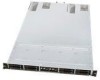
Intel® Server System SR1670HV Service Guide Intel Part Number: E74138-004 A Guide for Technically Qualified Assemblers of Intel® Identified Subassemblies/Products - Intel SR1670HV | Service Guide - Page 2
Xeon are trademarks or registered trademarks of Intel Corporation or its subsidiaries in the United States and other countries. * Other names and brands may be claimed as the property of others. Copyright © 2010, Intel Corporation. All Rights Reserved ii Intel® Server System SR1670HV Service Guide - Intel SR1670HV | Service Guide - Page 3
Disclaimer Intel® Server System SR1670HV Service Guide iii - Intel SR1670HV | Service Guide - Page 4
may need, troubleshooting information, and instructions on how to add and replace components on the Intel® Server System SR1670HV. For the latest version of this manual, refer to the following Intel web site: http://support.intel.com/support/motherboards/server/SR1670HV/ Manual Organization Chapter - Intel SR1670HV | Service Guide - Page 5
Users Manual Spares and Configuration Guide Tested Hardware and Operating System List Supported Processors Supported Memory Driver (for an extensive list of drivers available) Operating System Driver (for operating system drivers) Firmware Update Intel® Server System SR1670HV Service Guide v - Intel SR1670HV | Service Guide - Page 6
and Support Jumpers 35 5.1.1 5.1.2 5.1.3 5.1.4 Clear RTC RAM (CLRTC1 35 VGA Controller Setting (3-pin VGA_SW1 36 DDR3 Voltage Control Setting (4-pin LVDDR3_SEL1, LVDDR3_SEL2) ...... 36 LAN Controller Setting (3-poin LAN_SW1, LAN_SW2 37 vi Intel® Server System SR1670HV Service Guide - Intel SR1670HV | Service Guide - Page 7
99 8.3 LAN Driver Installation 101 8.4 VGA Driver Installation 103 8.5 Management Applications and Utilities Installation 105 8.5.1 Running the Resource CD 105 8.5.2 Drivers Menu 105 8.5.3 Utilities Menu 106 8.5.4 Make Disk Menu 106 Intel® Server System SR1670HV Service Guide vii - Intel SR1670HV | Service Guide - Page 8
127 Avertissements sur l'accès au système 129 Avertissements sur le montage en rack 129 Décharges électrostatiques (ESD 130 ATTENTION 130 Autres risques ...130 viii Intel® Server System SR1670HV Service Guide - Intel SR1670HV | Service Guide - Page 9
Descarga electrostática (ESD 136 PRECAUCIÓN 136 Otros riesgos...136 PRECAUCIÓN 137 138 138 138 139 139 139 140 141 ESD) ...141 141 141 142 Intel® Server System SR1670HV Service Guide ix - Intel SR1670HV | Service Guide - Page 10
Figure 32. Releasing the Drive Tray 23 Figure 33. Placing a SATAII/SAS Hard Disk Drive on the Tray 23 Figure 34. Pushing the Tray 45. Disconnecting System Fan Cable 29 Figure 46. Lifting System Fan ...29 Figure 47. Inserting Fan Into the Fan Cage 29 x Intel® Server System SR1670HV Service Guide - Intel SR1670HV | Service Guide - Page 11
Controller Setting 37 Figure 63. Intel® ICH10R SATA Port SW RAID Setting 38 Figure 64. Force BIOS Recovery Setting 38 Figure 65. SATA Devices Menu 55 Figure 88. System Information Menu 56 Figure 89. System Memory Information Menu 56 Figure 90. Intel® Server System SR1670HV Service Guide xi - Intel SR1670HV | Service Guide - Page 12
Device 95 Figure 143. Insert RAID Driver Disk Screen 95 Figure 144. Intel ICH8R/ICH9R/ICH10R/DO SATA RAID Controller Item 96 Figure 145. Installing Red Hat* Enterprise 96 Figure 146. Driver Disk Y/N Screen 97 Figure 147. Driver Disk Source 97 xii Intel® Server System SR1670HV Service Guide - Intel SR1670HV | Service Guide - Page 13
166. Install Wizard for Aspeed* VGA Driver 104 Figure 167. Updating the VGA Driver 104 Figure 168. Completing the VGA Driver Installation 105 Figure 169. Drivers Menu ...105 Figure 170. Utilities Menu ...106 Figure 171. Make Disk Menu ...106 Intel® Server System SR1670HV Service Guide xiii - Intel SR1670HV | Service Guide - Page 14
1 and 2 LEDs Descriptions 7 Table 6. HDD LED Status Definitions 7 Table 7. Maximum Memory Allocation Using RDIMMs 16 Table 8. Supported RDIMM Configurations 17 Table 9. Supported UDIMM Configurations 17 Table 10. Memory Population Table 18 xiv Intel® Server System SR1670HV Service Guide - Intel SR1670HV | Service Guide - Page 15
List of Tables Intel® Server System SR1670HV Service Guide xv - Intel SR1670HV | Service Guide - Page 16
and 5600 Series (two per server node) Intel® 5500 Chipset IOH Intel® 82801Jx I/O Controller Hub (ICH10R) 24 x DIMM slots (12 DIMM per server node/6 per processor) Support for 800/1066/1333 MT/s ECC registered (RDIMM) or unbuffered (UDIMM) DDR3 memory. Intel® Server System SR1670HV Service Guide 1 - Intel SR1670HV | Service Guide - Page 17
Bays-four for each installed server node. ƒ Dual independent front control panels-one for each installed server node. ƒ Features found on each front control panel include: System Power and System Reset buttons, LED indicators, and one 2.0 USB port. 2 Intel® Server System SR1670HV Service Guide - Intel SR1670HV | Service Guide - Page 18
node. ƒ Add-in card slot covers for each installed server node. ƒ External I/O ports for each installed server node. Figure 2. System Features - Back Panel 1.5 Internal Features The following figure shows the internal features of the server system. Intel® Server System SR1670HV Service Guide 3 - Intel SR1670HV | Service Guide - Page 19
Modules Riser Card Server Node 1 4 x System Fans Node 1 Server Node 2 Hard Disk Drive Bay Module 4 x System Fans Node 2 Figure 3. System Component Identification The following figure identifies connectors and major components of each server node. 4 Intel® Server System SR1670HV Service Guide - Intel SR1670HV | Service Guide - Page 20
Product Introduction A B C Q D P O N E M L K F G G H H I I J Figure 4. Server Node Connectors and Components Intel® Server System SR1670HV Service Guide 5 - Intel SR1670HV | Service Guide - Page 21
to turn off). BMC reset in progress when re-plug Power cord No LAN connection LAN is transmitting or receiving data. LAN connection is present. 6 Intel® Server System SR1670HV Service Guide - Intel SR1670HV | Service Guide - Page 22
pre-connected before shipment. You do not need to disconnect these cables unless you must remove pre-installed components for servicing or to install additional devices. Refer to Chapter 4, "System Service" for detailed information on the connections. Intel® Server System SR1670HV Service Guide 7 - Intel SR1670HV | Service Guide - Page 23
connector (from server board to front control panel) 5. Front Control Panel connector (from server board to front control panel) 6. SATA connectors (from server board to backplane) 7. Auxiliary Panel connector (from server board to front control panel) 8 Intel® Server System SR1670HV Service Guide - Intel SR1670HV | Service Guide - Page 24
surface mount LGA 1366 CPU sockets designed for the Intel® Xeon® Processor 5500 series and 5600 series. CAUTIONS Upon purchase of the server board, ensure the PnP caps are installed on each processor socket and the socket contacts are not bent. Contact Intel® Server System SR1670HV Service Guide 9 - Intel SR1670HV | Service Guide - Page 25
it is released from the retention tab. CAUTION To prevent damage to the socket pins, do not remove the PnP cap unless you are installing a processor. 10 Intel® Server System SR1670HV Service Guide - Intel SR1670HV | Service Guide - Page 26
socket, and then fit the socket alignment key into the processor notch. CAUTION The processor fits in only one correct orientation. DO NOT force the processor into the socket to prevent bending the connectors on the socket and damaging the processor! Intel® Server System SR1670HV Service Guide 11 - Intel SR1670HV | Service Guide - Page 27
-applied thermal interface material.) Apply several drops of thermal paste to the exposed area of the processor the heatsink will be in contact with, ensuring it is spread in an even, thin layer. load lever (B) until it snaps into the retention tab. 12 Intel® Server System SR1670HV Service Guide - Intel SR1670HV | Service Guide - Page 28
If you are reusing a heatsink, make sure there is adequate TIM present on the heatsink to support processor cooling. To install the heatsink, follows these steps: 1. Remove the protective film on the tightened up to a maximum of 8 inch-pounds torque. Intel® Server System SR1670HV Service Guide 13 - Intel SR1670HV | Service Guide - Page 29
slightly to break the seal between the heatsink and the processor. 3. Lift the heatsink from the processor. If it does not pull up easily, twist the heatsink again. Do not force the heatsink from the processor. Doing so could damage the processor. 14 Intel® Server System SR1670HV Service Guide - Intel SR1670HV | Service Guide - Page 30
DIMM_F2 when dual processors are installed on a given server node. On a given server node, DIMM sockets DIMM_D1 through DIMM_F2 are not enabled in single processor configurations. The following figure illustrates the location of the DDR3 DIMM sockets. Intel® Server System SR1670HV Service Guide 15 - Intel SR1670HV | Service Guide - Page 31
20. DDR3 DIMM Sockets Location 2.3.2 Memory Support Supported memory follows the DDR3 specification and meets the following characteristics: ƒ to support Quad Rank x4 DDR3 DIMMs, the Intel® Server System SR1670HV does not support this memory type. 16 Intel® Server System SR1670HV Service Guide - Intel SR1670HV | Service Guide - Page 32
ECC; however, x8 SDDC is supported in lock step mode with x8 UDIMMs with ECC. NOTE: Although non-ECC memory can be used in this server system, Intel does not plan to validate them and strongly discourages their use in a working server environment. Intel® Server System SR1670HV Service Guide 17 - Intel SR1670HV | Service Guide - Page 33
supply. Failure to do so may cause severe damage to both the server board and the components. 1. Unlock a DIMM socket by pressing the retaining clips outward. 2. Align a DIMM on the socket so the notch on the DIMM matches the break on the socket. 18 Intel® Server System SR1670HV Service Guide - Intel SR1670HV | Service Guide - Page 34
to disengage the DIMM from the socket. Figure 23. DIMM Notch NOTE: Support the DIMM lightly with your fingers when pressing the retaining clips. The DIMM might get damaged when it flips out with extra force. 2. Remove the DIMM from the socket. Intel® Server System SR1670HV Service Guide 19 - Intel SR1670HV | Service Guide - Page 35
Express* x 16 Card 4. Press the riser card bracket until the golden connectors completely fit the slot and the bracket aligns with the rear panel. 20 Intel® Server System SR1670HV Service Guide - Intel SR1670HV | Service Guide - Page 36
Hardware Setup Figure 27. Pressing Rising Card Bracket for Golden Connectors to Fit 5. If applicable, connect the cable(s) to the card. Intel® Server System SR1670HV Service Guide 21 - Intel SR1670HV | Service Guide - Page 37
be disabled. This power on delay is required to reset the BMC controller on the BMC Management Module. Once the BMC reset is complete, the System ID LED will turn off, and the power button functionality will be reenabled. 22 Intel® Server System SR1670HV Service Guide - Intel SR1670HV | Service Guide - Page 38
Hardware Setup 2.6 Hard Disk Drives The system supports up to eight hot-swap 2.5-inch SATAII/SAS hard disk drives-four for each installed server node. Each installed hard disk is mounted to a drive tray. When its front edge aligns with the bay edge. Intel® Server System SR1670HV Service Guide 23 - Intel SR1670HV | Service Guide - Page 39
Hardware Setup Figure 34. Pushing the Tray Lever 6. Repeat Steps 1 through 5 to add additional hard drives to the system. 24 Intel® Server System SR1670HV Service Guide - Intel SR1670HV | Service Guide - Page 40
to the Server To attach the server rails: 1. Attach the front end of the server rail to the side of the chassis, matching each of the three hooks to the holes on the rail, and then slide the rail towards the front panel until it locks into place. Intel® Server System SR1670HV Service Guide 25 - Intel SR1670HV | Service Guide - Page 41
determine the length of the rack rails. 5. Measure the rack rail when assembled to ensure it fits the rack. 6. Position the rack rail to the 1U space on the rack. Ensure the front end of the rack rail goes to the front of the rack space. 26 Intel® Server System SR1670HV Service Guide - Intel SR1670HV | Service Guide - Page 42
the Server To mount the server to the rack: 1. Align the server rails with the rack rails, and then push the server all the way to the depth of the rack. 2. Drive a screw on the mounting ear to secure the server in place. Figure 41. Mounting Ear Intel® Server System SR1670HV Service Guide 27 - Intel SR1670HV | Service Guide - Page 43
the PSU Latch 3. Firmly pull the failed PSU out of the server chassis. Figure 43. Pulling Out the Failed PSU 4. Firmly push the new PSU into the chassis until the latch locks to the server chassis. Figure 44. Pushing the New PSU Into the Chassis 28 Intel® Server System SR1670HV Service Guide - Intel SR1670HV | Service Guide - Page 44
fan: 1. Insert the fan into the fan cage. The airflow directional arrow on the fan side should point towards the system rear panel. Figure 47. Inserting Fan Into the Fan Cage 2. Connect the system fan cable to the fan connector on the server board. Intel® Server System SR1670HV Service Guide 29 - Intel SR1670HV | Service Guide - Page 45
49. Screws On Hard Disk Drive Bay Module 4. Slide the HDD bay module forward approximately ½ inch (1.27cm) and lift front edge of module from alignment guide slots. Figure 50. Sliding the Hard Disk Drive Bay Module 30 Intel® Server System SR1670HV Service Guide - Intel SR1670HV | Service Guide - Page 46
pair to the correct backplane connectors. 11. Unpack the replacement backplane. 12. Reconnect the front panel cable pairs to the correct connectors on the backplane. Intel® Server System SR1670HV Service Guide 31 - Intel SR1670HV | Service Guide - Page 47
system fan assembly as shown SATA 1 SATA 2 SATA 4 SATA 3 Figure 54. SATA Cable Connection Order 16. Carefully reposition the hard drive bay module on to the server chassis, such that the module falls within alignment slots on each side of the chassis. 32 Intel® Server System SR1670HV Service Guide - Intel SR1670HV | Service Guide - Page 48
both server modules and remove AC power. 2. Remove the single screw holding the Control Panel Module in place. Figure 56. Control Panel Module Screw 3. Carefully pull back the Control Panel module until the cables are fully exposed and accessible. Intel® Server System SR1670HV Service Guide 33 - Intel SR1670HV | Service Guide - Page 49
into the module bay until the screw holes are in alignment. 12. Using the single screw, fasten the Control Panel module to the chassis. 34 Intel® Server System SR1670HV Service Guide - Intel SR1670HV | Service Guide - Page 50
. Removing the cap causes system boot failure! NOTE: If the steps above do not help, remove the onboard battery and move the jumper again to clear the CMOS RTC RAM data. After the CMOS clearance, reinstall the battery. Figure 59. Clear RTC RAM Intel® Server System SR1670HV Service Guide 35 - Intel SR1670HV | Service Guide - Page 51
only, and will only be supported after Intel has validated their functionality. This document will be updated with full usage information once validation is complete and tested LV DDR3 DIMMs are added to the Tested Memory List for this server board. 36 Intel® Server System SR1670HV Service Guide - Intel SR1670HV | Service Guide - Page 52
poin LAN_SW1, LAN_SW2) These jumpers allow you to enable or disable the onboard Intel® 82574LGigabit LAN controllers. Set to pins 1-2 to activate the Gigabit LAN feature. place the jumper caps on pins 2-3 to use the Intel® Matrix Storage Manager (IMSM) Intel® Server System SR1670HV Service Guide 37 - Intel SR1670HV | Service Guide - Page 53
) and the AFUDOS.EXE utility. 2. Set the jumper to pins 2-3. 3. Insert the USB flash and turn on the system to update the BIOS. 4. Shut down the system. 5. Set the jumper back to pins 1-2. 6. Turn on the system. Figure 64. Force BIOS Recovery Setting 38 Intel® Server System SR1670HV Service Guide - Intel SR1670HV | Service Guide - Page 54
module cables to connectors USB3, and then install the modules to a slot opening at the back of the system chassis. These USB connectors comply with USB 2.0 specification which supports up to 480 Mbps connection speed. Figure 66. USB 2.0 Connectors Intel® Server System SR1670HV Service Guide 39 - Intel SR1670HV | Service Guide - Page 55
. Front Fan Connectors 5.2.4 Serial General Purpose Input/Output Connector (6-1 pin SGPIO1) This connector is used for the SGPIO peripherals for the LSI* Software RAID and Intel® Matrix RAID SATA LED. Figure 68. Serial General Purpose I/O Connector 40 Intel® Server System SR1670HV Service Guide - Intel SR1670HV | Service Guide - Page 56
These connectors allow you to connect SMBus (System Management Bus) to the power supply unit to read PSU information. Devices communicate with a SMBus host and/or other SMBus devices using the SMBus interface. Figure 70. Power Supply SMBus Connectors Intel® Server System SR1670HV Service Guide 41 - Intel SR1670HV | Service Guide - Page 57
optical drives. This connector has the following pin-out and board location: +12 V GND GND +5V Figure 72. Peripheral Power Connector (4-pin PWR3) 5.2.9 System Panel Connector (20-pin PANEL1) This connector supports several chassis-mounted functions. 42 Intel® Server System SR1670HV Service Guide - Intel SR1670HV | Service Guide - Page 58
. Pressing the power switch for more than four seconds while the system is ON turns the system OFF. 5.2.9.6 Reset button (2-pin RESET) This 2-pin connector is for the chassis-mounted reset button for system reboot without turning off the system power. Intel® Server System SR1670HV Service Guide 43 - Intel SR1670HV | Service Guide - Page 59
to this 2-pin connector. The LEDs will light up when the Locator button is pressed. 5.2.10.5 System ID Button/Switch (2-pin LOCATORBTN) These leads are for the locator button on the front panel. This button queries the state of the system locator. 44 Intel® Server System SR1670HV Service Guide - Intel SR1670HV | Service Guide - Page 60
5.3.2 CPU Warning LED (ERR_CPU1, ERR_CPU2) The CPU warning LEDs light up to indicate an impending failure of the corresponding CPU. Figure 76. ERR CPU LED Intel® Server System SR1670HV Service Guide 45 - Intel SR1670HV | Service Guide - Page 61
when plug power cord until the BMC reset complete. 5.3.4 BMC LED (BMC_LED1) The server board includes a BMC LED. With the BMC Management Module installed, this LEDs blinks once per second to indicate the BMC is operating. Figure 78. BMC LED (BMC_LED1) 46 Intel® Server System SR1670HV Service Guide - Intel SR1670HV | Service Guide - Page 62
this chapter for instructions on how to access the BIOS Setup utility and make this change. 3. At the DOS prompt, type the name of the batch file where ## is the BIOS revision. The BIOS update begins as soon as the key is pressed. Intel® Server System SR1670HV Service Guide 47 - Intel SR1670HV | Service Guide - Page 63
Process In the unlikely event your system BIOS gets corrupted, you should complete the following BIOS recovery process: 1. Download the latest BIOS or System Update Package from the following Intel Web Site http://support.intel.com/support/motherboards/server/SR1670HV/ 2. Extract all the files from - Intel SR1670HV | Service Guide - Page 64
persons with in-depth knowledge of server configuration make changes to BIOS settings. Incorrectly setting many of the options available can negatively impact the operation of the server. Intel recommends using default BIOS settings whenever possible. Intel® Server System SR1670HV Service Guide 49 - Intel SR1670HV | Service Guide - Page 65
to the server. Advanced: Provides several sub-menus used to configure server sub-system features and functions. Care should be taken when changing options in this section. Making uninformed changes can alter system behavior to an undesired state. 50 Intel® Server System SR1670HV Service Guide - Intel SR1670HV | Service Guide - Page 66
of the menu screen is a brief description of the selected item. 6.3.3 Main Menu Upon entering the BIOS Setup Utility, the Main menu screen displays, providing options to view basic system information and view/configure any SATA devices detected. Intel® Server System SR1670HV Service Guide 51 - Intel SR1670HV | Service Guide - Page 67
then press to display the device information. Figure 84. SATA1-4 Submenu Fields displayed in gray are information that the BIOS has obtained directly from the device, and may include the following: Device Type, Vendor, Size, LBA Mode, Block 52 Intel® Server System SR1670HV Service Guide - Intel SR1670HV | Service Guide - Page 68
BIOS Updates and and to the device occurs multiple sectors at a time if the device supports multi-sector transfer feature. When set to [Disabled], the data transfer from the system. Select an item then press if you want to configure the item. Intel® Server System SR1670HV Service Guide 53 - Intel SR1670HV | Service Guide - Page 69
BIOS Updates and Configuration Figure 85. IDE Configuration Menu 6.3.3.4.1 SATA Configuration [Enhanced] Configuration options: [Disabled] [Compatible] [Enhanced] Configure SATA as [IDE] Sets the configuration for the Serial ATA connectors supported Intel® Server System SR1670HV Service Guide - Intel SR1670HV | Service Guide - Page 70
BIOS Updates and Configuration Figure 86. system. Configuration options: [Auto] [Not Installed] 6.3.3.5.4 SMART Monitoring [Enabled] Allows you to set the Self-Monitoring, Analysis and Reporting Technology. Configuration options: [Disabled] [Enabled] Intel® Server System SR1670HV Service Guide - Intel SR1670HV | Service Guide - Page 71
option that provides information for each detected DIMM attached to Processors 1 and 2. Information provided for each installed DIMM includes: Slot ID, size, rank, speed, and current operating temperature. Figure 89. System Memory Information Menu 56 Intel® Server System SR1670HV Service Guide - Intel SR1670HV | Service Guide - Page 72
BIOS Setup Utility. Figure 90. Advanced Menu 6.3.4.1 CPU Configuration Sub-Menu The items in this menu display the CPU-related information that the BIOS automatically detects. Some items may not display if your CPU does not support the related functions. Intel® Server System SR1670HV Service Guide - Intel SR1670HV | Service Guide - Page 73
BIOS Updates and Configuration Figure 91. CPU Configuration Menu Scroll down for more items. Figure 92. CPU Configuration Menu, Continued 6.3.4.1.1 C1E Support [Enabled] Allows you to enable or disable Enhanced Halt State support ] [Enabled] 58 Intel® Server System SR1670HV Service Guide - Intel SR1670HV | Service Guide - Page 74
CPU speed is controlled by the operating system. Configuration options: [Disabled] [Enabled] 6.3.4.1.13 Intel TurboMode Tech [Enabled] When enabled, Turbo Mode allows processor cores to run faster than its marked frequency in certain conditions. Intel® Server System SR1670HV Service Guide 59 - Intel SR1670HV | Service Guide - Page 75
Sub-Menu The Chipset configuration menu allows you to change advanced chipset settings. Select an item then press to display the sub-menu. 60 Intel® Server System SR1670HV Service Guide - Intel SR1670HV | Service Guide - Page 76
BIOS Updates and Configuration 6.3.4.3 Figure 93. Chipset Configuration Menu CPU Bridge Chipset Configuration Sub-Menu Figure 94. CPU Bridge Chipset Configuration Menu Scroll down for more items. Intel® Server System SR1670HV Service Guide 61 - Intel SR1670HV | Service Guide - Page 77
] [Lockstep] [Sparing] 6.3.4.3.9 Memory ECC Function [Enabled] Allows you to enable or disable Memory ECC function. Configuration options: [Disabled] [Enabled] 6.3.4.3.10 Double Rate Refresh [Auto] Configuration options: [Disabled] [Auto] 62 Intel® Server System SR1670HV Service Guide - Intel SR1670HV | Service Guide - Page 78
. If BIOS detects that the installed DIMMs have faulty or missing thermal sensors, then OLTT will be enabled. When the Memory Thermal Throttling option is set to any setting except [Disabled], the following additional options displays on the screen: Intel® Server System SR1670HV Service Guide 63 - Intel SR1670HV | Service Guide - Page 79
. South Bridge Chipset Configuration Menu 6.3.4.5.1 USB Functions [Enabled] Allows you to configure the amount of USB ports to be enabled. Configuration options: [Disabled] [Enabled] 64 Intel® Server System SR1670HV Service Guide - Intel SR1670HV | Service Guide - Page 80
BIOS Intel VT-d [Disabled] Allows you to enable or disable the Intel® Virtualization Technology for Directed I/O. Configuration options: [Disabled] [Enabled] 6.3.4.7 Legacy Device Configuration Sub-Menu Figure 99. Legacy Device Configuration Menu Intel® Server System SR1670HV Service Guide - Intel SR1670HV | Service Guide - Page 81
BIOS Updates and Configuration 6.3.4.7.1 Serial Legacy USB Support [Enabled] Allows you to enable or disable support for legacy USB devices. Setting to [Auto] allows the system to detect the Mbps). Configuration options: [FullSpeed] [HiSpeed] 66 Intel® Server System SR1670HV Service Guide - Intel SR1670HV | Service Guide - Page 82
EHCI Hand-Off [Enabled] Enables or disables the BIOS EHCI hand-off support. Configuration options: [Disabled] [Enabled] 6.3.4.9 PCIPnP Configuration Sub-Menu The PCIPnP this item to [Bus N First]. Configuration options: [Bus 0 First] [Bus N First] Intel® Server System SR1670HV Service Guide 67 - Intel SR1670HV | Service Guide - Page 83
BIOS Updates and Configuration 6.3.4.9.3 Onboard Option ROM Priority [High] Allows you to select the onboard option ROM priority. Allows you to enable or disable RTC to generate a wake-up event. Configuration options: [Disabled] [Enabled] 68 Intel® Server System SR1670HV Service Guide - Intel SR1670HV | Service Guide - Page 84
system event log. 6.3.4.11.2 Make all events as read Press the key to mark all events as read. Select [Ok] to confirm the change. 6.3.4.11.3 Clear Event Log Press the key to clear all system events. Select [Ok] to confirm the change. Intel® Server System SR1670HV Service Guide - Intel SR1670HV | Service Guide - Page 85
BIOS Updates and Configuration 6.3.4.12 Hardware Monitor Sub-Menu and displays the processor temperatures. Select [Ignored] if you do not want to display the detected temperatures. 6.3.4.12.2 System Fan1-4 Speed [ do not want to detect this item. 70 Intel® Server System SR1670HV Service Guide - Intel SR1670HV | Service Guide - Page 86
BIOS Updates and Configuration 6.3.4.13 I/O Virtualization Sub-Menu 6.3.4.13.1 SR-IOV Supported [Disabled] Configuration options: [Enable] [Disabled] 6.3.4.14 PCI Express* 6.3.4.15 ACPI Configuration Sub-Menu Figure 107. ACPI Configuration Menu Intel® Server System SR1670HV Service Guide 71 - Intel SR1670HV | Service Guide - Page 87
BIOS Updates and Configuration 6.3.4.15.1 Advanced ACPI Configuration Sub-Menu Figure 108. Advanced ACPI Configuration Menu 6.3.4.15.2 ACPI 2.0 Support [Enabled] Specifies the Advanced Configuration and Power Interface (ACPI) version supported ] 72 Intel® Server System SR1670HV Service Guide - Intel SR1670HV | Service Guide - Page 88
you to configure IPMI and Remote Connectivity options. Figure 111. Server Menu 6.3.5.1 IPMI Configuration Sub-Menu Information and Options found under this menu selection are only available with the BMC Management Module installed in the system. Intel® Server System SR1670HV Service Guide 73 - Intel SR1670HV | Service Guide - Page 89
] Enables or disables the remote access feature. Configuration options: [Disabled] [Enabled] NOTE: The following items display only when Remote Access is set to [Enabled]. 74 Intel® Server System SR1670HV Service Guide - Intel SR1670HV | Service Guide - Page 90
the VT-UTF8 combo key support for ANSI or VT100 terminals. Configuration options: [Disabled] [Enabled] 6.3.6 Boot Menu The Boot menu items allow you to change the system boot options. Select an item and then press to display the sub-menu. Intel® Server System SR1670HV Service Guide 75 - Intel SR1670HV | Service Guide - Page 91
BIOS Updates and Configuration 6.3.6.1 Figure 113. Boot Menu Boot Device Priority Figure 114. Boot Device Priority Menu 6.3.6.1.1 1st ~ xxth Boot Device drives. The hard drive set as the "1st Drive" will be listed in the Boot Device Priority List. 76 Intel® Server System SR1670HV Service Guide - Intel SR1670HV | Service Guide - Page 92
system waits for the key to be pressed when a POST error occurs. Configuration options: [Disabled] [Enabled] 6.3.6.3.6 Hit 'F2' Message Display [Enabled] When set to [Enabled], the system displays the message "Press F2 to run Setup" during POST. Intel® Server System SR1670HV Service Guide - Intel SR1670HV | Service Guide - Page 93
BIOS Updates and Configuration Configuration options: [Disabled] [Enabled] 6.3.6.3.7 Interrupt 19 Capture [Enabled] When set to [Enabled], press . 2. In the pop-up window, hit the key 3. The message "Password Uninstalled" displays. 78 Intel® Server System SR1670HV Service Guide - Intel SR1670HV | Service Guide - Page 94
[Setup] When set to [Setup], BIOS checks for the User password when accessing the BIOS Setup utility. When set to [Always], BIOS checks for the User password both when accessing Setup and booting the system. Configuration options: [Setup] [Always] Intel® Server System SR1670HV Service Guide 79 - Intel SR1670HV | Service Guide - Page 95
. Select Exit & Save Changes or make other changes before saving the values to the non-volatile RAM. NOTE: Pressing the anytime while in the BIOS Setup Utility will also reset all BIOS setting defaults. 80 Intel® Server System SR1670HV Service Guide - Intel SR1670HV | Service Guide - Page 96
the respective SATA SW RAID Users Guides included on the System Resource CD, or download them from the following Intel website: http://support.intel.com/support/motherboards/server/SR1670HV/ 7.1 Selecting a RAID option Embedded on the server board are options to support either of two SATA Software - Intel SR1670HV | Service Guide - Page 97
1. Power on the system. During POST, the LSI* MegaRAID option ROM automatically detects installed SATA hard disk drives and displays any existing RAID set(s). 2. Press the + hot-keys together to access the RAID configuration utility. 82 Intel® Server System SR1670HV Service Guide - Intel SR1670HV | Service Guide - Page 98
RAID Set. Use the following process to create a RAID set: 1. Select either the Easy Configuration or NEW Configuration from the Configuration Menu and press . Intel® Server System SR1670HV Service Guide 83 - Intel SR1670HV | Service Guide - Page 99
selecting each drive to be included in the RAID set, press the key to configure settings. 3. Press to select the configurable array. 84 Intel® Server System SR1670HV Service Guide - Intel SR1670HV | Service Guide - Page 100
Drive Menu 5. Select RAID from the Virtual Drive sub-menu, and then press . 6. Select the RAID level from the menu, and then press . Intel® Server System SR1670HV Service Guide 85 - Intel SR1670HV | Service Guide - Page 101
the Virtual Drive Configuration 10. Repeat the preceding steps to configure additional RAID sets if needed. 11. Press to finish the RAID configuration. 86 Intel® Server System SR1670HV Service Guide - Intel SR1670HV | Service Guide - Page 102
to select the virtual drive to initialize. 2. Use the arrow keys to select the virtual drive from the Virtual Drive selection, and then press . Intel® Server System SR1670HV Service Guide 87 - Intel SR1670HV | Service Guide - Page 103
bar displays on screen. If necessary, pressing the key can be used to stop the initialization process. 4. When initialization is completed, press . 88 Intel® Server System SR1670HV Service Guide - Intel SR1670HV | Service Guide - Page 104
to display the adapter properties. 2. Select Disk WC, and then press to turn on the option. Figure 134. Selecting the Disk WC Option Intel® Server System SR1670HV Service Guide 89 - Intel SR1670HV | Service Guide - Page 105
server board is configured to support the Intel® Matrix Storage Manager RAID option. Otherwise, refer to the section describing the LSI* SATA Software RAID Utility. This section provides an overview and press . The following screen appears. 90 Intel® Server System SR1670HV Service Guide - Intel SR1670HV | Service Guide - Page 106
and press . The default value indicates the maximum allowed capacity. When the Create Volume option is selected, press . The following warning message displays: Intel® Server System SR1670HV Service Guide 91 - Intel SR1670HV | Service Guide - Page 107
VOLUME menu. 9. From the utility Main Menu, select 5. Exit and then press . The following warning message appears. Figure 139. Intel® Matrix Storage Manager Warning Message 10. Press to exit or press to return to the utility main menu. 92 Intel® Server System SR1670HV Service Guide - Intel SR1670HV | Service Guide - Page 108
computer allowing the system to boot from the Resource CD. The Create Driver Diskette menu displays. Figure 140. Makedisk Menu 6. Use the arrow keys to select the type of RAID driver disk you want to create and press to enter the sub-menu. Intel® Server System SR1670HV Service Guide 93 - Intel SR1670HV | Service Guide - Page 109
* operating system: 1. Boot the computer using the Windows® Server installation DVD. The Windows® Server Operating System Setup starts. Figure 141. Microsoft Windows Server* Setup Menu 2. When prompted, Press to install a third-party driver. 94 Intel® Server System SR1670HV Service Guide - Intel SR1670HV | Service Guide - Page 110
controller item, then select Properties. 6. Click the Driver tab, and then click the Update Driver button. 7. The Upgrade Device Driver Wizard window appears. Click Next. 8. Insert the RAID driver disk (you created earlier) into the floppy disk drive. Intel® Server System SR1670HV Service Guide 95 - Intel SR1670HV | Service Guide - Page 111
1. Boot the system from the Red Hat* Installation CD. 2. At the boot:, type linux dd, and then press . Figure 145. Installing Red Hat* Enterprise 3. Select Yes using the key when asked if you have the driver disk, and then press . 96 Intel® Server System SR1670HV Service Guide - Intel SR1670HV | Service Guide - Page 112
. Insert Driver Disk Screen 6. When asked if you will load additional RAID controller drivers, select No, and then press . Figure 149. More Driver Disks? Screen 7. Follow the onscreen instructions to continue the operating system installation. Intel® Server System SR1670HV Service Guide 97 - Intel SR1670HV | Service Guide - Page 113
. Initializing the SuSe* Installation 4. Insert the RAID driver disk to the floppy disk drive. Make sure Installation from the Boot Options menu is selected, and then press . Figure 152. Installation Option Selected on the Boot Options Screen 98 Intel® Server System SR1670HV Service Guide - Intel SR1670HV | Service Guide - Page 114
Drivers menu if Autorun is enabled in your computer. 3. Click the item Intel Chipset Device Software from the menu. Figure 154. Intel Chipset Device Software Option 4. The Intel® Chipset Device Software window appears. Click Next to start installation. Intel® Server System SR1670HV Service Guide - Intel SR1670HV | Service Guide - Page 115
Driver Installation Figure 155. Intel® Chipset Device Software Window 5. Select Yes to accept the terms of the License Agreement and continue File Information Window 7. After completing the installation, click Finish to complete the setup process. 100 Intel® Server System SR1670HV Service Guide - Intel SR1670HV | Service Guide - Page 116
folder. Double-click the ASSETUP.EXE to run the CD. 3. Click the Intel Network Connections Software to begin installation. Figure 159. Intel Network Connections Software Option 4. Click the Install Drivers and Software option to begin installation. Intel® Server System SR1670HV Service Guide 101 - Intel SR1670HV | Service Guide - Page 117
-InstallShield Wizard 6. Toggle I accept the terms in the license agreement and click Next to continue. Figure 162. License Agreement Terms 7. Click the Intel(R) PROSet for Windows Device Manager box, and then click Next to start the installation. 102 Intel® Server System SR1670HV Service Guide - Intel SR1670HV | Service Guide - Page 118
log on with Administrator privileges. 2. Insert the server board/system Resource CD to the optical drive. The CD automatically displays the Drivers menu if Autorun is enabled in your computer. The Drivers menu if Autorun is enabled in your computer. Intel® Server System SR1670HV Service Guide 103 - Intel SR1670HV | Service Guide - Page 119
the installation. Figure 166. Install Wizard for Aspeed* VGA Driver 4. Click Install to update the VGA driver. Figure 167. Updating the VGA Driver 5. When the installation completes, click Finish to restart your computer before using the program. 104 Intel® Server System SR1670HV Service Guide - Intel SR1670HV | Service Guide - Page 120
shows the available device drivers if the system detects installed devices. Install the necessary drivers to activate the devices. NOTE: The screen display and driver options vary under different operating system versions. Figure 169. Drivers Menu Intel® Server System SR1670HV Service Guide 105 - Intel SR1670HV | Service Guide - Page 121
Make Disk Menu The Make Disk menu provides options to create driver installation floppy disks for supported operating systems. Figure 171. Make Disk Menu 8.5.5 Contact Information For contact information, refer to the "Contact Information" section. 106 Intel® Server System SR1670HV Service Guide - Intel SR1670HV | Service Guide - Page 122
Support Case Intel® Server Board or System: (Example : S5500HV or SR1670HV Server BIOS been tried? (Yes/No): Has the latest BMC/mBMC been tried? (Yes/No): Has the latest IMM BMC been tried? (Yes/No): Has the latest RMM Firmware been tried? (Yes/No): Intel® Server System SR1670HV Service Guide - Intel SR1670HV | Service Guide - Page 123
? Add-in adapters (Example: NICs, Management Adapters, Serial Expansion Cards, PCI-Express* Adapters, RAID Controllers, SCSI Controllers, etc.) Type Slot Manufacturer Model Firmware Third party hardware (Example: Example: KVM, Chassis, etc) 108 Intel® Server System SR1670HV Service Guide - Intel SR1670HV | Service Guide - Page 124
/Retail Intel® RAID Controller: (Example SRCU42E) RAID controller part number (PBA number): RAID controller firmware version: Has the latest RAID firmware been tried? (Yes/No): RAID driver version: Has the latest RAID driver been tried? (Yes/No): Intel® Server System SR1670HV Service Guide 109 - Intel SR1670HV | Service Guide - Page 125
description of issue: Troubleshooting tried: Steps to replicate the issue: Issue impact statements: Do you have any potential Intel system, or component purchases that this issue is holding up? If yes, please provide a brief description below. 110 Intel® Server System SR1670HV Service Guide - Intel SR1670HV | Service Guide - Page 126
please provide a brief description below. Have you returned systems or components to your place of purchase because of this issue? If yes, please provide a brief description below. *All other brands and names are property of their respective owners. Intel® Server System SR1670HV Service Guide 111 - Intel SR1670HV | Service Guide - Page 127
: Latest BIOS, firmware, drivers and utilities Product documentation, installation and quick start guides Full product specifications, technical advisories and errata Compatibility documentation for memory, hardware add-in cards, chassis support matrix and operating systems Server and chassis - Intel SR1670HV | Service Guide - Page 128
todas las declaraciones de seguridad y precaución de este documento antes de realizar cualquiera de las instrucciones. Vea Intel Server Boards and Server Chassis Safety Information en http://support.intel.com/support/motherboards/server/safecert.htm. Intel® Server System SR1670HV Service Guide 113 - Intel SR1670HV | Service Guide - Page 129
hazards that result in serious injury or death if safety instructions are not followed. Indicates hot components or surfaces. Indicates do not touch fan blades, may result in injury. Indicates to unplug all AC power cord(s) to disconnect AC power 114 Intel® Server System SR1670HV Service Guide - Intel SR1670HV | Service Guide - Page 130
power cord from the wall outlet. Your system may use more than one AC power cord. Make sure all AC power cords are unplugged. Make sure the AC power cord(s) is/are unplugged before you open the chassis, or add or remove any non hot-plug components. Intel® Server System SR1670HV Service Guide 115 - Intel SR1670HV | Service Guide - Page 131
System Access Warnings CAUTION To avoid personal injury or property damage, the following safety instructions apply system by pressing the power button to off. ƒ Disconnect the AC power by unplugging all AC power cords from the system or wall outlet. 116 Intel® Server System SR1670HV Service Guide - Intel SR1670HV | Service Guide - Page 132
accessible, and it must be labeled as controlling power to the entire unit, not just to the server(s). To avoid risk of potential electric shock, a proper safety ground must be implemented for the rack and each piece of equipment installed in it. Intel® Server System SR1670HV Service Guide 117 - Intel SR1670HV | Service Guide - Page 133
edges. After removing a board from its protective wrapper or from the server, place the board component side up on a grounded, static free surface. Use a conductive foam pad if available but not the board wrapper. Do not slide board over any surface. 118 Intel® Server System SR1670HV Service Guide - Intel SR1670HV | Service Guide - Page 134
instructions. Laser Peripherals or Devices CAUTION To avoid risk of radiation exposure and/or personal injury: Do not open the enclosure of any laser peripheral or device Laser peripherals or devices have are not user serviceable Return to manufacturer for servicing Intel® Server System SR1670HV - Intel SR1670HV | Service Guide - Page 135
Safety Information Deutsch Sicherheitshinweise für den Server Das vorliegende Dokument bezieht sich auf Intel® Serverplatinen, Intel® Servergehäuse (Standfuß und Rack) sowie Netzkabel abzuziehen und das Gerät von der Netzspannung zu trennen. 120 Intel® Server System SR1670HV Service Guide - Intel SR1670HV | Service Guide - Page 136
das System eingesteckt ist. Um das System vollständig vom Strom zu trennen, muß das Netzkabel aus der Steckdose abgezogen werden. Das System verfügt möglicherweise über mehrere Netzkabel. Vergewissern Sie sich in diesem Fall, daß alle Netzkabel Intel® Server System SR1670HV Service Guide 121 - Intel SR1670HV | Service Guide - Page 137
und verwenden Sie kein Kabel, das nicht genau dem geforderten Typ entspricht. Jedes Netzteil im System muß über ein eigenes Netzkabel angeschlossen werden. Das Netzteil in diesem Produkt enthält alle am Produkt angeschlossenen Peripheriegeräte aus. 122 Intel® Server System SR1670HV Service Guide - Intel SR1670HV | Service Guide - Page 138
Einheit steuert und nicht nur zu den Servern. Zur Vermeidung von Stromschlaggefahr müssen das Rack selbst und alle darin eingebauten Geräte ordnungsgemäß geerdet sein. Intel® Server System SR1670HV Service Guide 123 - Intel SR1670HV | Service Guide - Page 139
aus dem Server mit der Systems ohne Abdeckung kann zur Beschädigung von Systemkomponenten führen. So bringen Sie die Abdeckung wieder an: 1. Vergewissern Sie sich zunächst, daß Sie keine Werkzeuge oder Teile im Gehäuse vergessen haben. 124 Intel® Server System SR1670HV Service Guide - Intel SR1670HV | Service Guide - Page 140
äten oder LaserKomponenten. Laser-Peripheriegeräte oder -Komponenten besitzen keine für den Benutzer wartungsbedürftigen Teile. Schicken Sie das Gerät für Wartungsarbeiten an den Hersteller zurück. Intel® Server System SR1670HV Service Guide 125 - Intel SR1670HV | Service Guide - Page 141
par des techniciens qualifiés. Vous devez suivre les informations de ce guide et les instructions d'assemblage des manuels de serveur pour vérifier et maintenir la conformit les cordons d'alimentation secteur pour déconnecter l'alimentation. 126 Intel® Server System SR1670HV Service Guide - Intel SR1670HV | Service Guide - Page 142
du système car le courant de veille 5 V reste actif lorsque le système est sous tension. Pour couper l'alimentation du système, vous devez Intel® Server System SR1670HV Service Guide 127 - Intel SR1670HV | Service Guide - Page 143
ƒ Les cordons d'alimentation doivent répondre aux critères suivants : Le cordon d'alimentation doit supporter une intensité supérieure à celle indiquée sur le produit. Le cordon d'alimentation doit prises électriques correctement reliées à la terre. 128 Intel® Server System SR1670HV Service Guide - Intel SR1670HV | Service Guide - Page 144
doit être fixé à un support inamovible pour éviter qu'il instructions du fabricant. Installez les équipements dans le rack en partant du bas, en plaçant le plus lourd en bas du rack. N'étendez qu'un seul élément de l'équipement à partir du rack à la fois. Intel® Server System SR1670HV Service Guide - Intel SR1670HV | Service Guide - Page 145
et ventilation ATTENTION Routez les câbles avec précaution comme indiqué pour minimiser les blocages de circulation d'air et les problèmes de refroidissement. 130 Intel® Server System SR1670HV Service Guide - Intel SR1670HV | Service Guide - Page 146
composants sont correctement installés. 3. Fixez les panneaux au châssis en suivant les instructions du produit. Périphériques laser ATTENTION Pour éviter tout risque d'exposition aux rayonnements . Retournez-les au fabricant en cas de problème. Intel® Server System SR1670HV Service Guide 131 - Intel SR1670HV | Service Guide - Page 147
ñirse a las directrices de esta guía y a las instrucciones de montaje de los manuales del servidor para asegurar y mantener el cumplimiento con las certificaciones y homologaciones existentes de los ón de CA para desconectar la alimentación de CA 132 Intel® Server System SR1670HV Service Guide - Intel SR1670HV | Service Guide - Page 148
ón de CA con el sistema. Asegúrese de que todos los cables de alimentación de CA están desenchufados. Asegúrese de que los cables de Intel® Server System SR1670HV Service Guide 133 - Intel SR1670HV | Service Guide - Page 149
se acceda al interior del producto: ƒ Apague todos los dispositivos periféricos conectados a este producto. ƒ Pulse el botón de alimentación para apagar el sistema. 134 Intel® Server System SR1670HV Service Guide - Intel SR1670HV | Service Guide - Page 150
evitar el riesgo de descargas eléctricas, deberá instalar una conexión a tierra apropiada para el bastidor y para cada pieza del equipo instalada en el mismo. Intel® Server System SR1670HV Service Guide 135 - Intel SR1670HV | Service Guide - Page 151
dentro del sistema. 2. Compruebe que los cables, tarjetas adicionales y otros componentes están instalados correctamente. 3. Sujete las cubiertas a la carcasa siguiendo las instrucciones del producto. 136 Intel® Server System SR1670HV Service Guide - Intel SR1670HV | Service Guide - Page 152
caja de ningún periférico o dispositivo láser Los periféricos o dispositivos láser no pueden ser reparados por el usuario Haga que el fabricante los repare Intel® Server System SR1670HV Service Guide 137 - Intel SR1670HV | Service Guide - Page 153
Safety Information Intel Intel Intel Web UL 注意 警告 ITE ITE 138 Intel® Server System SR1670HV Service Guide - Intel SR1670HV | Service Guide - Page 154
Safety Information 5V Intel® Server System SR1670HV Service Guide 139 - Intel SR1670HV | Service Guide - Page 155
Safety Information 140 Intel® Server System SR1670HV Service Guide - Intel SR1670HV | Service Guide - Page 156
Safety Information ESD) ESD ESD ESD ESD 其他危险 Intel® Server System SR1670HV Service Guide 141 - Intel SR1670HV | Service Guide - Page 157
Safety Information 1 2 142 Intel® Server System SR1670HV Service Guide
-
 1
1 -
 2
2 -
 3
3 -
 4
4 -
 5
5 -
 6
6 -
 7
7 -
8
-
9
-
10
-
11
-
12
-
13
-
14
-
15
-
16
-
17
-
18
-
19
-
20
-
21
-
22
-
23
-
24
-
25
-
26
-
27
-
28
-
29
-
30
-
31
-
32
-
33
-
34
-
35
-
36
-
37
-
38
-
39
-
40
-
41
-
42
-
43
-
44
-
45
-
46
-
47
-
48
-
49
-
50
-
51
-
52
-
53
-
54
-
55
-
56
-
57
-
58
-
59
-
60
-
61
-
62
-
63
-
64
-
65
-
66
-
67
-
68
-
69
-
70
-
71
-
72
-
73
-
74
-
75
-
76
-
77
-
78
-
79
-
80
-
81
-
82
-
83
-
84
-
85
-
86
-
87
-
88
-
89
-
90
-
91
-
92
-
93
-
94
-
95
-
96
-
97
-
98
-
99
-
100
-
101
-
102
-
103
-
104
-
105
-
106
-
107
-
108
-
109
-
110
-
111
-
112
-
113
-
114
-
115
-
116
-
117
-
118
-
119
-
120
-
121
-
122
-
123
-
124
-
125
-
126
-
127
-
128
-
129
-
130
-
131
-
132
-
133
-
134
-
135
-
136
-
137
-
138
-
139
-
140
-
141
-
142
-
143
-
144
-
145
-
146
-
147
-
148
-
149
-
150
-
151
-
152
-
153
-
154
-
155
-
156
-
157
 |
 |

Intel
®
Server System SR1670HV
Service Guide
Intel Part Number: E74138-004
A Guide for Technically Qualified Assemblers of Intel
®
Identified Subassemblies/Products