Intel SR2500ALLXR User Guide
Intel SR2500ALLXR - Server System - 0 MB RAM Manual
 |
UPC - 735858197212
View all Intel SR2500ALLXR manuals
Add to My Manuals
Save this manual to your list of manuals |
Intel SR2500ALLXR manual content summary:
- Intel SR2500ALLXR | User Guide - Page 1
Intel® Server System SR2500AL User's Guide A Guide for Technically Qualified Assemblers of Intel® Identified Subassemblies/ Products Intel Order Number D31969-004 - Intel SR2500ALLXR | User Guide - Page 2
are trademarks or registered trademarks of Intel Corporation or its subsidiaries in the United States and other countries. * Other names and brands may be claimed as the property of others. Copyright © 2006-2007, Intel Corporation. All Rights Reserved ii Intel® Server System SR2500AL User's Guide - Intel SR2500ALLXR | User Guide - Page 3
statements in this document before performing any of the instructions. See also Intel Server Boards and Server Chassis Safety Information on the Intel® Deployment Assistant CD and/or at http://support.intel.com/support/motherboards/ server/sb/cs-010770.htm. Wichtige Sicherheitshinweise Lesen Sie zun - Intel SR2500ALLXR | User Guide - Page 4
http://support.intel.com/support/motherboards/server/sb/CS-010770.htm 上的 Intel Server Boards and Server Chassis Safety Information(《Intel iv Intel® Server System SR2500AL User's Guide - Intel SR2500ALLXR | User Guide - Page 5
the contacts inside the jumper, causing intermittent problems with the function controlled by that jumper. Take care to grip with, but not squeeze, the pliers or other tool you use to remove a jumper, or you may bend or break the pins on the board. Intel® Server System SR2500AL User's Guide v - Intel SR2500ALLXR | User Guide - Page 6
vi Intel® Server System SR2500AL User's Guide - Intel SR2500ALLXR | User Guide - Page 7
information, feature information, and step by step instructions on how to add and replace components on the server system. For the latest version of this manual, see http:// support.intel.com/support/motherboards/server/chassis/SR2500/. Manual Organization Chapter 1 provides a list of reference - Intel SR2500ALLXR | User Guide - Page 8
The Intel® Server System SR2500ALLX and/or the Intel® Server System SR2500ALBRP ships with the Intel® Server Board S5000PAL. For further information, see the Intel® Server Board S5000PAL User's Guide. There are two versions of this server system: the Intel® Server System SR2500ALLX/ SR2500ALLXR (SAS - Intel SR2500ALLXR | User Guide - Page 9
component, in the hardware box • Rack handles, in the hardware box • Peripheral bay filler panel, in the hardware box • Standard control panel, installed in the server system • Passive mid-plane, installed in the server system Intel® Server System SR2500AL User's Guide ix - Intel SR2500ALLXR | User Guide - Page 10
x Intel® Server System SR2500AL User's Guide - Intel SR2500ALLXR | User Guide - Page 11
viii Intel® Server System SR2500ALLX/SR2500ALLXR Contents viii Intel® Server System SR2500ALBRP/SR2500ALBRPR Contents ix Chapter 1: Server System References 1 Chapter 2: Server System Features 3 Chassis Component Identification 6 Internal Components ...6 Configuration Jumpers ...9 RAID Support - Intel SR2500ALLXR | User Guide - Page 12
64 Installing the I/O Expansion Module(s 66 Removing the I/O Expansion Module(s 67 Installing the Intel® RMM and Intel® RMM NIC 68 Removing the Intel® RMM and Intel® RMM NIC 70 Replacing the Mid-plane Board 71 Removing the Mid-plane Board 71 xii Intel® Server System SR2500AL User's Guide - Intel SR2500ALLXR | User Guide - Page 13
105 Appendix A: Technical Reference 107 Cable Routing ...107 Fan Connections ...108 750W Single Power Supply Input Voltages 109 750W Single Power Supply Output Voltages 109 System Environmental Specifications 110 Appendix B: Troubleshooting 111 Intel® Server System SR2500AL User's Guide xiii - Intel SR2500ALLXR | User Guide - Page 14
Key System Lights 113 Confirming Loading of the Operating System 113 Specific Problems System) ...119 Hard Drive(s) are not Recognized 119 Bootable CD-ROM Disk Is Not Detected 119 LED Information ...120 BIOS POST Beep Codes 120 Appendix C: Intel® Server Intel® Server System SR2500AL User's Guide - Intel SR2500ALLXR | User Guide - Page 15
Appendix G: Warranty 149 Limited Warranty for Intel® Chassis Subassembly Products 149 Appendix H: Installation/Assembly Safety Instructions 153 English ...153 Deutsch ...155 Franç d'électricit 177 Avertissements sur le cordon d'alimentation 178 Intel® Server System SR2500AL User's Guide xv - Intel SR2500ALLXR | User Guide - Page 16
de alimentación 183 Advertencias el acceso al sistema 184 Advertencias sobre el montaje en bastidor 185 Descarga electrostática (ESD 185 Otros riesgos ...186 xvi Intel® Server System SR2500AL User's Guide - Intel SR2500ALLXR | User Guide - Page 17
17. Front Bezel Supporting the Intel® Local Control Panel 28 Figure 18. Removing the Front Bezel 29 Figure 19. Installing the Front Bezel 30 Figure 20. Removing the Server System Cover 31 Figure 21. Installing the Server System Cover 32 Figure 22. Removing the Processor Air Duct 33 Figure - Intel SR2500ALLXR | User Guide - Page 18
Server System 76 Figure 67. Installing the RAID Activation Key and the RAID Mini DIMM 77 Figure 68. Removing the RAID Activation Key and the RAID Mini DIMM 78 Figure 69. Installing the RAID Battery Backup Unit 79 Figure 70. Removing the RAID Battery Intel® Server System SR2500AL User's Guide - Intel SR2500ALLXR | User Guide - Page 19
-plane Board . 108 Figure 95. Connecting the Redundant Fan Power Cables to the Active Mid-plane Board.... 108 Figure 96. Diagnostic LED Placement Diagram 128 Intel® Server System SR2500AL User's Guide xix - Intel SR2500ALLXR | User Guide - Page 20
xx Intel® Server System SR2500AL User's Guide - Intel SR2500ALLXR | User Guide - Page 21
Table 1. Server System References 1 Table 2. Intel® Server System SR2500ALLX and/or the Intel® Server System SR2500ALBRP Feature Summary ...4 Table 3. NIC LED Descriptions 13 Table 4. Setup Menu Key Use 102 Table 5. Power Supply Output Capability 109 Table 6. System Environmental Specifications - Intel SR2500ALLXR | User Guide - Page 22
xxii Intel® Server System SR2500AL User's Guide - Intel SR2500ALLXR | User Guide - Page 23
in-depth firmware information on the Baseboard Management Controller (BMC) For in-depth information on Intel® I/O Acceleration Technology Use this Document or Software Intel® Server Chassis SR2500 Technical Product Specification Found at: http://support.intel.com/support/motherboards/server/chassis - Intel SR2500ALLXR | User Guide - Page 24
virtual system tours and interactive repair information A link to the SMaRT Tool is available under "Other Resources" at the right side of the screen at http://support.intel.com/support/motherboards/server/chassis/ SR2500 Accessories or other Intel server products Spares and Configuration Guide - Intel SR2500ALLXR | User Guide - Page 25
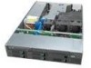
describes the main features of the server system. This chapter provides illustrations of the product, a list of the server system features, and diagrams showing the location of important components and connections on the server system. AF000027 Figure 1. Intel® Integrated Server System SR2500AL - Intel SR2500ALLXR | User Guide - Page 26
Table 2 summarizes the features of the server system. Table 2. Intel® Server System SR2500ALLX and/or the Intel® Server System SR2500ALBRP Feature Summary Feature Dimensions Server Board Processor Memory Chipset Peripheral Interfaces I/O Controll Video LAN Expansion Capabilities Description • 3.44 - Intel SR2500ALLXR | User Guide - Page 27
Table 2. Intel® Server System SR2500ALLX and/or the Intel® Server System SR2500ALBRP Feature Summary Feature Hard Drives Peripherals Control Panel (dependent on option selected) LEDs and displays (dependent on option selected) Description • Five hot-swap SATA / SAS drives • Drive bay for sixth hot - Intel SR2500ALLXR | User Guide - Page 28
(supports M. Flex Bay - 6th HDD or Tape Drive (optional) up to two power supply modules) F. Riser Card Assembly N. Hard Drive Bays G. Integrated Chassis Intrusion Switch O. Slimline Optical Drive Bay H. System Memory (below duct in illustration) Figure 2. ChassisComponents 6 Intel® Server - Intel SR2500ALLXR | User Guide - Page 29
Server Board Connector and Component Locations A B C D EF GH I QQ J PP K OO L NN MM LL KK M JJ II N HH GG FF EE DD O CC BB P AA Z Q Y X W V U TS R TP02071 Intel® Server System SR2500AL User's Guide 7 - Intel SR2500ALLXR | User Guide - Page 30
+ IO) X. Main Power Connector AA. Dual Port USB 2.0 Header DD. SATA Port 0 GG. SATA Port 3 JJ. SATA SW RAID 5 Activation Key Connector MM. Chassis Intrusion Switch Header PP. Serial A Header Figure 3. Server Board Connector and Component Locations 8 Intel® Server System SR2500AL User's Guide - Intel SR2500ALLXR | User Guide - Page 31
Normal Operation (Default) Jumper Name BIOS Select TP02087 Jumper Purpose If pins 1-2 are jumpered, the BIOS in the lower bank will be selected on the next reset. These pins should be jumpered on 2-3 for normal operation. Figure 4. BIOS Select Jumper Intel® Server System SR2500AL User's Guide 9 - Intel SR2500ALLXR | User Guide - Page 32
normal operation. If pins 2-3 are jumpered, BMC Force Update Mode is enabled. These pins should be jumpered on 1-2 for normal operation. Figure 5. Recovery Jumpers 10 Intel® Server System SR2500AL User's Guide - Intel SR2500ALLXR | User Guide - Page 33
H. DIMM C1 Fault I. DIMM C2 Fault J. DIMM D1 Fault K. DIMM D2 Fault L L. CPU 1 Fault M M. CPU 2 Fault N. 5V Standby CPU 2 CPU 1 Socket Socket AF000644 Figure 6. Light Guided Diagnostic LEDs Intel® Server System SR2500AL User's Guide 11 - Intel SR2500ALLXR | User Guide - Page 34
Back Panel Connectors A B C D E F GH TP02081 A. Mouse C. Serial Port B (RJ45) E. NIC 2 (10/100/1000 Mb) G. USB Port 6 B. Keyboard D. NIC 1 (10/100/1000 Mb) F. Video H. USB Port 5 Figure 7. Back Panel Connectors 12 Intel® Server System SR2500AL User's Guide - Intel SR2500ALLXR | User Guide - Page 35
the Intel® RAID Activation Key AXXRAKSW5 accessory to enable RAID 5, see the documentation that is included with the accessory kit. For information on configuring RAID, see the RAID software user's guide that is included on the Intel® Server Deployment Toolkit 2.0 CD. Intel® Server System SR2500AL - Intel SR2500ALLXR | User Guide - Page 36
server board, hot-swap backplane, and control panel. Two midplanes are offered for this system: a passive SATA (data cables required), and an active SAS/SATA RAID used in the Intel® Server System SR2500ALLX and/or the Intel® Server System SR2500ALBRP. 14 Intel® Server System SR2500AL User's Guide - Intel SR2500ALLXR | User Guide - Page 37
A. RAID Battery Connector B. Mid-plane Power Connector C. Fan 6 Power D. Fan 5 Power E. Bridge Board Connector F. Fan 4 Power G. Fan 3 Power H. Fan 2 Power I. Fan 1 Power J. Backplane Connectors Figure 9. Active SAS/SATA Mid-Plane Components Intel® Server System SR2500AL User's Guide 15 - Intel SR2500ALLXR | User Guide - Page 38
show the location for each connector found on the backplane. A B C D AF000045 A. Optical Drive Connector B. USB Floppy Connector C. Control Panel Connector D. SAS/SATA Connectors Figure 10. Hot-Swap SAS/SATA Backplane Components (Front View) . 16 Intel® Server System SR2500AL User's Guide - Intel SR2500ALLXR | User Guide - Page 39
A BC D E AF000044 A. Flex Bay Power B. Flex Bay Data C. IDE Connector D. Backplane Power E. Data Connectors (one for the flex bay and one for the mid-plane) Figure 11. Hot-Swap SAS/SATA Backplane Components (Rear View) Intel® Server System SR2500AL User's Guide 17 - Intel SR2500ALLXR | User Guide - Page 40
or the system is off. Solid blue indicates system identification is active. No light indicates system identification is not activated. Solid blue indicates system identification is active. No light indicates system identification is not activated. 18 Intel® Server System SR2500AL User's Guide - Intel SR2500ALLXR | User Guide - Page 41
. No light indicates system identification is not activated. Continuous green light indicates the system has power applied to it. Blinking green indicates the system is in S1 sleep state. No light indicates the power is off / is in ACPI S4 or S5 state. Intel® Server System SR2500AL User's Guide 19 - Intel SR2500ALLXR | User Guide - Page 42
through the server chassis. Two bezels are available. One fits a system that has the standard control panel installed. The other is used for a chassis with the other Intel® Local Control Panel. Each bezel provides a lock to secure the hard drive and optical drive area. For instructions on installing - Intel SR2500ALLXR | User Guide - Page 43
Supply Module G. Server Management NIC (Optional) H. I/O Module (Optional) I. USB 6 J. USB 5 K. Video L. DB-9 Serial A Connector Knockout M. NIC 2 N. NIC 1 O. RJ45 Serial B Connector P. PS2* Keyboard and Mouse Connectors Figure 14. Server System Back Intel® Server System SR2500AL User's Guide 21 - Intel SR2500ALLXR | User Guide - Page 44
) hot-swap drives. Note: SAS drives are supported on the Intel® Server System SR2500ALLX/SR2500ALLXR only. One left drive bay can be converted to be used as a floppy bay. To use the bay for a floppy drive, the AXXFLOPHDDTRAY accessory kit must be used. For instructions on installing hard drives, see - Intel SR2500ALLXR | User Guide - Page 45
Module, see the instructions provided with the management module. Rack-Mounted Systems Your Intel® Server System SR2500ALLX and/or the Intel® Server System SR2500ALBRP can be mounted into a rack. Intel provides three options to mount this server into a rack. When installing the chassis into a rack - Intel SR2500ALLXR | User Guide - Page 46
24 Intel® Server System SR2500AL User's Guide - Intel SR2500ALLXR | User Guide - Page 47
are available to install the Intel® Server System SR2500ALLX and/or the Intel® Server System SR2500ALBRP in a rack. The options are the fixed bracket kit, the basic rail kit, and the tool-less rail kit. Only the tool-less rail kit allows you to service the server system while installed in a rack - Intel SR2500ALLXR | User Guide - Page 48
of the chassis with the finger tab facing outward and located closer to the rear of the chassis. 4. Align the holes in the rail with the tabs on the chassis and place the rail against the chassis. 5. attach the other rail assembly to the other side. 26 Intel® Server System SR2500AL User's Guide - Intel SR2500ALLXR | User Guide - Page 49
to the server chassis) with the outer rail assemblies (attached to the rack). 9. Engage the matching rails and slide the server chassis into the rack until the two safety stops lock into position. 10. Depress the two safety locks (one on each side). Intel® Server System SR2500AL User's Guide 27 - Intel SR2500ALLXR | User Guide - Page 50
is at the right. If you are installing a bezel on your server system, make sure you position it as shown. AF000154 Figure 16. Front Bezel Supporting the Standard Control Panel AF000153 Figure 17. Front Bezel Supporting the Intel® Local Control Panel 28 Intel® Server System SR2500AL User's Guide - Intel SR2500ALLXR | User Guide - Page 51
Removing the Front Bezel Use the steps below if your system includes a front bezel. 1. Unlock the bezel. 2. Disconnect any cables attached to the control panel. 3. Pull the bezel from the server system. TP02129 Figure 18. Removing the Front Bezel Intel® Server System SR2500AL User's Guide 29 - Intel SR2500ALLXR | User Guide - Page 52
removing the chassis cover, power down the server and unplug all peripheral devices and the AC power cable(s). Note: A nonskid surface or a stop behind the server system may be needed to prevent the server system from sliding on your work surface. 30 Intel® Server System SR2500AL User's Guide - Intel SR2500ALLXR | User Guide - Page 53
system sidewalls. 2. Slide the cover forward until it clicks into place (see letter "A"). 3. (Optional) Insert the safety screw at the center of the top cover (see letter "B") if required. 4. Reconnect all peripheral devices and the AC power cord(s). Intel® Server System SR2500AL User's Guide - Intel SR2500ALLXR | User Guide - Page 54
". 2. Power down the server and unplug all peripheral devices and the AC power cable. 3. Remove the server system cover. For instructions, see "Removing the System Cover". 4. Lift the processor air duct from its location over the two processor sockets. 32 Intel® Server System SR2500AL User's Guide - Intel SR2500ALLXR | User Guide - Page 55
TP02131 Figure 22. Removing the Processor Air Duct Intel® Server System SR2500AL User's Guide 33 - Intel SR2500ALLXR | User Guide - Page 56
caution not to pinch or disengage cables that may be near or under the air duct. 7. Install the server system cover. For instructions, see "Installing the Server System Cover". 8. Plug all peripheral devices and the AC power cable(s) into the server. 34 Intel® Server System SR2500AL User's Guide - Intel SR2500ALLXR | User Guide - Page 57
Turn off the server. 3. Disconnect the AC power cord(s) from the server. 4. Remove the server's cover. See the documentation that came with your server chassis for instructions on removing the server's cover. 5. Locate the DIMM sockets (see Figure 25). Intel® Server System SR2500AL User's Guide 35 - Intel SR2500ALLXR | User Guide - Page 58
D1 Socket DIMM D2 Socket D A C B Figure 25. Installing the Memory TP02072 6. Make sure the clips at either end of the DIMM socket(s) of the DIMM with the key in the DIMM socket. The arrow in the inset in Figure 7 is pointing to the key in the socket (see Intel® Server System SR2500AL User's Guide - Intel SR2500ALLXR | User Guide - Page 59
in damage to the system. Installing the Processor To install a processor, follow these instructions: 1. Observe the safety and ESD precautions in "Safety Information". 2. Turn off all peripheral devices connected to the server. Turn off the server. Intel® Server System SR2500AL User's Guide 37 - Intel SR2500ALLXR | User Guide - Page 60
the server. 4. Remove the server's cover. See the documentation that came with your server chassis for instructions on removing the server's cover. 5. Locate the processor socket cover for use when removing a processor that will not be replaced. 38 Intel® Server System SR2500AL User's Guide - Intel SR2500ALLXR | User Guide - Page 61
the TIM. 1. Set the heat sink over the processor, lining up the four captive screws with the four posts surrounding the processor. 2. Loosely screw in the captive screws on the 4 TP02077 Figure 29. Installing the Heat Sink (2U Passive Heat Sink Shown) Intel® Server System SR2500AL User's Guide 39 - Intel SR2500ALLXR | User Guide - Page 62
and reconnect any parts you removed or disconnected to reach the processor sockets. 5. Replace the server's cover and reconnect the AC power cord(s). See the documentation that came with your server chassis for instructions on installing the server's cover. Removing a Processor 1. Observe the safety - Intel SR2500ALLXR | User Guide - Page 63
down the server and unplug all peripheral devices and the AC power cable(s). 3. Remove the server system cover. For instructions, see "Removing the System Cover". 4. the server system. 2. Snap the baffle into place as shown in the figure below. TP02136 Intel® Server System SR2500AL User's Guide 41 - Intel SR2500ALLXR | User Guide - Page 64
all peripheral devices and the AC power cable(s). 3. Remove the server system cover. For instructions, see "Removing the System Cover". 4. Note how the cables are routed over and under the air baffle (if any). You will need to re-route these cables. 42 Intel® Server System SR2500AL User's Guide - Intel SR2500ALLXR | User Guide - Page 65
. 2. While setting the baffle into place, route the cables beneath it appropriately. See Appendix , "Cable Routing" or the Quick Reference Label that came with your system for help in determining where the cables should be routed. Intel® Server System SR2500AL User's Guide 43 - Intel SR2500ALLXR | User Guide - Page 66
of supported hardware. Installing a SAS or SATA Hot-swap Hard Disk Drive 1. Remove the front bezel if it is installed. For instructions, see "Removing the Front Bezel". 2. Open the latch at the front of the hard drive carrier. See letter "A" in the figure below. 44 Intel® Server System SR2500AL - Intel SR2500ALLXR | User Guide - Page 67
antistatic surface. 6. Set any jumpers and/or switches on the drive according to the drive manufacturer's instructions. 7. With the drive circuit-side down, position the connector end of the drive so that it attached to the plastic retention device. Intel® Server System SR2500AL User's Guide 45 - Intel SR2500ALLXR | User Guide - Page 68
the server system cover. For instructions, see "Installing the Server System Cover". 12. (Optional) Install the front bezel. For instructions, see "Installing the Front Bezel". 13. Plug all peripheral devices and the AC power cable(s) into the server. 46 Intel® Server System SR2500AL User's Guide - Intel SR2500ALLXR | User Guide - Page 69
connected to the system, turn off the system by pressing the power button, and unplug the AC power cord from the system or wall outlet. To maintain proper system cooling, a filler blank must be installed if you do not install a device at this location. Intel® Server System SR2500AL User's Guide 47 - Intel SR2500ALLXR | User Guide - Page 70
front bezel if it is installed. For instructions, see "Removing the Front Bezel". 4. Remove the server system cover. For instructions, see "Removing the System Cover". 5. Insert the interposer board into to the documentation that came with the device. 48 Intel® Server System SR2500AL User's Guide - Intel SR2500ALLXR | User Guide - Page 71
Server System 14. Install the server system cover. For instructions, see "Installing the Server System Cover". 15. (Optional) Install the front bezel. For instructions, slimline optical drive tray assembly from the server system as shown in Figure 40. Intel® Server System SR2500AL User's Guide 49 - Intel SR2500ALLXR | User Guide - Page 72
B C AF000151 Figure 40. Removing the Slimline Optical Drive Assembly from the Server System 7. Press downward on the side of the tray (see letter "A") and disengage tray. C B A AF000152 Figure 41. Removing the Slimline Optical Drive from the Tray 50 Intel® Server System SR2500AL User's Guide - Intel SR2500ALLXR | User Guide - Page 73
precautions at the beginning of this book. See "Safety Information". 2. Power down the server and unplug all peripheral devices and the AC power cable(s). 3. Remove the front bezel if it is installed. For instructions, see "Removing the Front Bezel". Intel® Server System SR2500AL User's Guide 51 - Intel SR2500ALLXR | User Guide - Page 74
Filler Panel from the Server System 6. Remove the hard drive blank that is installed in the sixth drive bay. See the figure below to locate the sixth drive filler panel. AF000035 Figure 44. Removing Sixth Drive Filler Panel from the Server System 52 Intel® Server System SR2500AL User's Guide - Intel SR2500ALLXR | User Guide - Page 75
drive into the combined tape drive bay/sixth drive bay until the carrier clicks into place. AF000033 Figure 46. Installing Tape Drive Assembly into the Server System Intel® Server System SR2500AL User's Guide 53 - Intel SR2500ALLXR | User Guide - Page 76
, see "Removing the Front Bezel". 4. Remove the server system cover. For instructions, see "Removing the System Cover". 5. Slide the sixth HDD bracket into the backplane as shown in the figure below. Figure 47. Installing Sixth HDD Bracket AF000012 54 Intel® Server System SR2500AL User's Guide - Intel SR2500ALLXR | User Guide - Page 77
in your system. If you have an active mid-plane in your system, go to step 7 for cabling instructions. If you have a passive mid-plane in your system, go to step 8 for cabling instructions. 7. from the 6th HDD kit in a system with an active mid- plane. Intel® Server System SR2500AL User's Guide 55 - Intel SR2500ALLXR | User Guide - Page 78
the server system cover. For instructions, see "Installing the Server System Cover". 11. (Optional) Install the front bezel. For instructions, see "Installing the Front Bezel". 12. Plug all peripheral devices and the AC power cable(s) into the server. 56 Intel® Server System SR2500AL User's Guide - Intel SR2500ALLXR | User Guide - Page 79
To remove the PCI riser assembly, use the following instructions. 1. Observe the safety and ESD precautions at the beginning of this book. See "Safety Information". 2. Power down the server and unplug all peripheral devices and the AC power cable(s). Intel® Server System SR2500AL User's Guide 57 - Intel SR2500ALLXR | User Guide - Page 80
3. Remove the server system cover. For instructions, see "Removing the System Cover". 4. Remove the processor air duct by lifting straight up. 5. Disconnect any cables attached the PCI riser assembly for another procedure, continue with that procedure. 58 Intel® Server System SR2500AL User's Guide - Intel SR2500ALLXR | User Guide - Page 81
the Processor Air Duct". 6. Install the server system cover. For instructions, see "Installing the Server System Cover". 7. (Optional) Install the front bezel. For instructions, see "Installing the Front Bezel". 8. Plug all peripheral devices and the AC power cable(s) into the server. Intel® Server - Intel SR2500ALLXR | User Guide - Page 82
Remove the server system cover. For instructions, see "Removing the System Cover". 4. Remove the processor air duct. For instructions, see "Removing the Processor Air Duct". ) and remove from the server system (see letter "C" in the figure below). 60 Intel® Server System SR2500AL User's Guide - Intel SR2500ALLXR | User Guide - Page 83
the processor air duct. For instructions, see "Installing the Processor Air Duct". 15. Install the server system cover. For instructions, see "Installing the Server System Cover". 16. Plug all peripheral devices and the AC power cable(s) into the server. Intel® Server System SR2500AL User's Guide - Intel SR2500ALLXR | User Guide - Page 84
Remove the server system cover. For instructions, see "Removing the System Cover". 4. Remove the processor air duct. For instructions, see "Removing the Processor Air Duct PCI Riser Card into the Server System 11. Release the blue locking lever. 62 Intel® Server System SR2500AL User's Guide - Intel SR2500ALLXR | User Guide - Page 85
Re-install the processor air duct. For instructions, see "Installing the Processor Air Duct". 16. Install the server system cover. For instructions, see "Installing the Server System Cover". 17. until it seats in riser card connector (see letter "D"). Intel® Server System SR2500AL User's Guide 63 - Intel SR2500ALLXR | User Guide - Page 86
system cover. For instructions, see "Removing the System Cover". 4. Remove the processor air duct. For instructions, see "Removing the Processor Air Duct". 5. Remove the PCI riser assembly. For instructions, see "Removing the PCI Riser Assembly". 64 Intel® Server System SR2500AL User's Guide - Intel SR2500ALLXR | User Guide - Page 87
the processor air duct. For instructions, see "Installing the Processor Air Duct". 12. Install the server system cover. For instructions, see "Installing the Server System Cover". 13. Plug all peripheral devices and the AC power cable(s) into the server. Intel® Server System SR2500AL User's Guide - Intel SR2500ALLXR | User Guide - Page 88
processor air duct. For instructions, see "Installing the Processor Air Duct". 9. Install the server system cover. For instructions, see "Installing the Server System Cover". 10. Plug all peripheral devices and the AC power cable(s) into the server. 66 Intel® Server System SR2500AL User's Guide - Intel SR2500ALLXR | User Guide - Page 89
the processor air duct. For instructions, see "Installing the Processor Air Duct". 10. Install the server system cover. For instructions, see "Installing the Server System Cover". 11. Plug all peripheral devices and the AC power cable(s) into the server. Intel® Server System SR2500AL User's Guide - Intel SR2500ALLXR | User Guide - Page 90
module to the server board (see letter "D" in the following figure). 8. Insert the standoff into the hole labeled TH4 on the Intel® RMM board (see letter "E" in the following figure). The standoff installs on the bottom side of the Intel® RMM board. 68 Intel® Server System SR2500AL User's Guide - Intel SR2500ALLXR | User Guide - Page 91
the processor air duct. For instructions, see "Installing the Processor Air Duct". 4. Install the server system cover. For instructions, see "Installing the Server System Cover". 5. Plug all peripheral devices and the AC power cable(s) into the server. Intel® Server System SR2500AL User's Guide 69 - Intel SR2500ALLXR | User Guide - Page 92
processor air duct. For instructions, see "Installing the Processor Air Duct". 11. Install the server system cover. For instructions, see "Installing the Server System Cover". 12. Plug all peripheral devices and the AC power cable(s) into the server. 70 Intel® Server System SR2500AL User's Guide - Intel SR2500ALLXR | User Guide - Page 93
Board from the Server System 6. Remove the fan module. For instructions, see "Replacing a Fan Module". 7. Hold the mid-plane board only by the edges. Slide the mid-plane board back to release it from the backplane (see letter "A" in the figure below). Intel® Server System SR2500AL User's Guide 71 - Intel SR2500ALLXR | User Guide - Page 94
. For instructions, see "Removing the System Cover". 4. Position the mid-plane board over the retention pins as shown in the figure below (see letter "A"). 5. Slide the mid-plane board forward (see letter "B") and insert the mid-plane into the backplane connector as shown. 72 Intel® Server System - Intel SR2500ALLXR | User Guide - Page 95
below), and inserting it into the connector on the server board (see letter "C" in the figure below. Close the retention mechanism to hold the bridge board in place. A C B C A AF000163 Figure 64. Installing the Bridge Board into the Server System Intel® Server System SR2500AL User's Guide 73 - Intel SR2500ALLXR | User Guide - Page 96
. For instructions, see "Removing a SAS or SATA Hot-swap Hard Disk Drive". 6. Disconnect all cables from the backplane. 7. Firmly grasp the top of the backplane and remove the backplane from the server system by pulling straight up as shown in the figure below. 74 Intel® Server System SR2500AL - Intel SR2500ALLXR | User Guide - Page 97
AF000016 Figure 65. Removing the Backplane from the Server System Intel® Server System SR2500AL User's Guide 75 - Intel SR2500ALLXR | User Guide - Page 98
66. Installing the Backplane into the Server System 8. Install hot-swap drive carriers. For instructions, see "Installing a SAS or SATA Hot-swap Hard Disk Drive". 9. Install the mid-plane board. For instructions, see "Installing the Mid-plane Board". 76 Intel® Server System SR2500AL User's Guide - Intel SR2500ALLXR | User Guide - Page 99
mechanism (see letter "B" in the figure below) and inserting the DIMM into the socket (see letter "C" in the figure below). A B B C AF000742 Figure 67. Installing the RAID Activation Key and the RAID Mini DIMM Intel® Server System SR2500AL User's Guide 77 - Intel SR2500ALLXR | User Guide - Page 100
Key and the RAID Mini DIMM 7. Install the large air baffle. For instructions, see "Installing the Large Air Baffle". 8. Install the server system cover. For instructions, see "Installing the Server System Cover". 9. Plug all peripheral devices and the AC power cable(s) into the server. 78 Intel - Intel SR2500ALLXR | User Guide - Page 101
A B AF000149 Figure 69. Installing the RAID Battery Backup Unit 7. Install the large air baffle. For instructions, see "Installing the Large Air Baffle". 8. Install the server system cover. For instructions, see "Installing the Server System Cover". Intel® Server System SR2500AL User's Guide 79 - Intel SR2500ALLXR | User Guide - Page 102
the RAID Battery Backup Unit 7. Install the large air baffle. For instructions, see "Installing the Large Air Baffle". 8. Install the server system cover. For instructions, see "Installing the Server System Cover". 9. Plug all peripheral devices and the AC power cable(s) into the server. 80 Intel - Intel SR2500ALLXR | User Guide - Page 103
instructions, see "Replacing a Fan Module". 10. Place the server board into the server system as shown in the figure below (see letter "A"), and attach the server board with six screws (see letter "B"). B A AF000025 Figure 71. Installing the Server Board Intel® Server System SR2500AL User's Guide - Intel SR2500ALLXR | User Guide - Page 104
fan module assembly. For instructions, see "Replacing a Fan Module". 10. Disconnect all cables from the server board. 11. Remove memory. For instructions, see "Removing DIMMs". 12. Remove the processor(s). For instructions, see "Removing a Processor". 82 Intel® Server System SR2500AL User's Guide - Intel SR2500ALLXR | User Guide - Page 105
the processor air duct. For instructions, see "Installing the Processor Air Duct". 22. Install the server system cover. For instructions, see "Installing the Server System Cover". 23. Plug all peripheral devices and the AC power cable(s) into the server. Intel® Server System SR2500AL User's Guide - Intel SR2500ALLXR | User Guide - Page 106
. Kassera använt batteri enligt fabrikantens instruktion. Varoitus: Paristo voi räjähtää, jos se on virheellisesti asennettu. Vaihda paristo ainoastaan laitevalmistajan suosittelemaan tyyppiin. Hävitä käytetty paristo valmistajan ohjeiden mukaisesti. 84 Intel® Server System SR2500AL User's Guide - Intel SR2500ALLXR | User Guide - Page 107
according to local ordinance. 8. Remove the new lithium battery from its package, and, being careful to observe the correct polarity, insert it in the battery socket. 9. Close the chassis. 10. Run Setup to restore the configuration settings to the RTC. Intel® Server System SR2500AL User's Guide 85 - Intel SR2500ALLXR | User Guide - Page 108
A AF000021 Figure 74. Removing Power Supply Filler Panel from the Server System 5. If a power supply is installed, release the latch (see letter "A") and remove the power supply by pulling on the handle (see letter "B") as shown in the figure below. 86 Intel® Server System SR2500AL User's Guide - Intel SR2500ALLXR | User Guide - Page 109
AF000023 Figure 77. Installing Power Supply Filler Panel into the Server System 8. Install the server system cover. For instructions, see "Installing the Server System Cover". 9. Plug all peripheral devices and the AC power cable(s) into the server. Intel® Server System SR2500AL User's Guide 87 - Intel SR2500ALLXR | User Guide - Page 110
Power Distribution Module AF000146 10. Set the replacement power supply distribution module into the server system and screw the module into place. 11. Install the hot-swap power supply/supplies. For instructions, see "Replacing the Power Supply". 88 Intel® Server System SR2500AL User's Guide - Intel SR2500ALLXR | User Guide - Page 111
the server and unplug all peripheral devices and the AC power cable(s). 3. Remove the front bezel if it is installed. For instructions, see "Removing the Front Bezel". 4. Remove the server system cover. For instructions, see "Removing the System Cover". Intel® Server System SR2500AL User's Guide - Intel SR2500ALLXR | User Guide - Page 112
Control Panel Module from the Server System 7. Slide the replacement control panel into the server system (see letter "A") until it clicks into place (see letter "B"). B A AF000006 Figure 80. Installing Control Panel Module into the Server System 90 Intel® Server System SR2500AL User's Guide - Intel SR2500ALLXR | User Guide - Page 113
the bridge board. For instructions, see Figure 61 "Removing the Bridge Board from the Server System" on page -71. 8. Remove the large air baffle. For instructions, see "Removing the Large Air Baffle". 9. Disconnect the fan cables from the mid-plane. Intel® Server System SR2500AL User's Guide 91 - Intel SR2500ALLXR | User Guide - Page 114
"B"). B A B A Figure 82. Installing the Redundant Fan Module 12. Connect the fan cables to the mid-plane. 13. Install the large air baffle. For instructions, see "Installing the Large Air Baffle". Re-route cables through the air baffle as necessary. 92 Intel® Server System SR2500AL User's Guide - Intel SR2500ALLXR | User Guide - Page 115
the bridge board. For instructions, see Figure 61 "Removing the Bridge Board from the Server System" on page -71. 8. Remove the large air baffle. For instructions, see "Removing the Large Air Baffle". 9. Disconnect the fan cables from the mid-plane. Intel® Server System SR2500AL User's Guide 93 - Intel SR2500ALLXR | User Guide - Page 116
to the left (see letter "B" in), and lifting the assembly off of the standoff and out of the system (see letter "C"). A B C B C Figure 83. Removing the Fixed Fan Module 11. Install the letter "B"). B A B A Figure 84. Installing the Fixed Fan Module 94 Intel® Server System SR2500AL User's Guide - Intel SR2500ALLXR | User Guide - Page 117
Observe the safety and ESD precautions at the beginning of this book. See "Safety Information". 2. Remove the server system cover. For instructions, see "Removing the System Cover". 3. There are no screws to loosen. Lift the failed fan from the module. Intel® Server System SR2500AL User's Guide 95 - Intel SR2500ALLXR | User Guide - Page 118
the connector on the fan into the matching connector on the fan module. 5 6 34 2 1 AF000009 Figure 86. Installing a Fan into the Redundant Fan Module 96 Intel® Server System SR2500AL User's Guide - Intel SR2500ALLXR | User Guide - Page 119
and pointing down. 7. With the fan oriented correctly, insert the fan into the fan module (see letter "A" in the figure below), and snap in place. Intel® Server System SR2500AL User's Guide 97 - Intel SR2500ALLXR | User Guide - Page 120
. For instructions, see "Removing the System Cover". 4. Align the rack handle with the two holes on the side of the server system as shown in the figure below. 5. Attach the rack handle to the server system with two screws as shown in the figure below. 98 Intel® Server System SR2500AL User's Guide - Intel SR2500ALLXR | User Guide - Page 121
"Removing the Front Bezel". 4. Remove the server system cover. For instructions, see "Removing the System Cover". 5. Remove the two screws holding the rack handle in place, and remove the rack handle from the server system as shown in the figure below. Intel® Server System SR2500AL User's Guide 99 - Intel SR2500ALLXR | User Guide - Page 122
AF000020 Figure 90. Removing the Rack Handle 6. Install the server system cover. For instructions, see "Installing the Server System Cover". 7. Plug all peripheral devices and the AC power cable(s) into the server. 100 Intel® Server System SR2500AL User's Guide - Intel SR2500ALLXR | User Guide - Page 123
System References" for a link to the Intel® 5000 Series Chipsets Server Board Family Datasheet where you will find details about specific BIOS setup screens. Starting Setup You can enter and start BIOS Setup under several conditions: • When you turn on the server, after POST completes the memory - Intel SR2500ALLXR | User Guide - Page 124
pressed, all Setup fields are set to their default values. If "No" is selected and the key is pressed, or if the key is pressed, the user is returned to where they were before was pressed without affecting any existing field values. 102 Intel® Server System SR2500AL User's Guide - Intel SR2500ALLXR | User Guide - Page 125
and press when you see the message: Press Key if you want to run SETUP 2. Write down the current settings in the BIOS Setup program. Note: Do not skip step 2. You will need these settings to configure your server at the end of the procedure. Intel® Server System SR2500AL User's Guide 103 - Intel SR2500ALLXR | User Guide - Page 126
Upgrade Download the BIOS image file to a temporary folder on your hard drive. See "Server System References" for a link to the update software. Note: Review the instructions and release notes that are provided in the readme file distributed with the BIOS image file before attempting a BIOS upgrade - Intel SR2500ALLXR | User Guide - Page 127
the configuration RAM. 1. Power down the system and disconnect the AC power. 2. Open the server. 3. Move the jumper from the normal operation position, CMOS Clear by BMC, at pins 1 and 2 to the CMOS Clear Force Erase position, covering pins 2 and 3. Intel® Server System SR2500AL User's Guide 105 - Intel SR2500ALLXR | User Guide - Page 128
. 5. Return the CMOS Clear jumper to the CMOS Clear by BMC location, covering pins 1 and 2. 6. Close the server chassis. 7. Reconnect the AC power and power up the system. 8. The CMOS is now cleared and can be reset by going into the BIOS setup. 106 Intel® Server System SR2500AL User's Guide - Intel SR2500ALLXR | User Guide - Page 129
remove components from your server system, make sure your cables are routed correctly before reinstalling the server system cover. Use caution to to Server Board (Aux.) B Power to Server Board (Main) C Power to Server Board (CPU) D Power to Midplane Board E Power to Backplane Board F RAID Battery to - Intel SR2500ALLXR | User Guide - Page 130
-redundant Fan Power Cables to the Passive Mid-plane Board 6 5 4 3 2 1 TP02140 Figure 95. Connecting the Redundant Fan Power Cables to the Active Midplane Board 108 Intel® Server System SR2500AL User's Guide - Intel SR2500ALLXR | User Guide - Page 131
90 Watts for the +5 V and +3.3 V outputs. Exceeding a combined 90 Watts will overload the power subsystem and may cause the power supplies to overheat and malfunction. Intel® Server System SR2500AL User's Guide 109 - Intel SR2500ALLXR | User Guide - Page 132
Environmental Specifications Table 6. System Environmental Specifications Temperature Non-operating Operating Humidity Non-operating Shock Operating Packaged Acoustic noise Electrostatic level. Tested to 15 kilovolts (kV); no component damage. 110 Intel® Server System SR2500AL User's Guide - Intel SR2500ALLXR | User Guide - Page 133
" for a link to the software updates. In addition to the server firmware and files, also update any drivers used for components you have installed in your system, such as video drivers, network drivers, and SATA drivers. Intel provides a package called the "Platform Confidence Test" that may help - Intel SR2500ALLXR | User Guide - Page 134
and chassis lists, as well as the supported hardware and operating system list. See "Server System References" for links to the tested component lists. Hardware Diagnostic Testing This section provides a more detailed approach to identifying a hardware problem and locating its source. 112 Intel - Intel SR2500ALLXR | User Guide - Page 135
Appear on Screen". Specific Problems and Corrective Actions This section provides possible solutions for these specific problems: • Power light does not light. • No characters appear on screen. • Characters on the screen appear distorted or incorrect. Intel® Server System SR2500AL User's Guide 113 - Intel SR2500ALLXR | User Guide - Page 136
Lock light is functioning. • Is the video monitor plugged in and turned on? If you are using a switch box, is it switched to the correct system? 114 Intel® Server System SR2500AL User's Guide - Intel SR2500ALLXR | User Guide - Page 137
Does this video monitor work correctly if plugged into a different system? System Cooling Fans Do Not Rotate Properly If the system cooling fans are not operating properly, it is an indication of possible system component failure. Check the following: Intel® Server System SR2500AL User's Guide 115 - Intel SR2500ALLXR | User Guide - Page 138
the network cable is securely attached to the correct connector at the system back panel. • Try a different network cable. • Make sure you are using the correct and the current drivers. See "Server System References" for a link to the current drivers. 116 Intel® Server System SR2500AL User's Guide - Intel SR2500ALLXR | User Guide - Page 139
the add-in adapter. The add-in adapter stopped working without apparent cause • Reseat the adater. • Put the adapter in a different slot. • The network driver files may be corrupt or deleted. Delete and then reinstall the drivers. • Run diagnostics. Intel® Server System SR2500AL User's Guide 117 - Intel SR2500ALLXR | User Guide - Page 140
drivers installed. If the problems persist, contact the software vendor's customer service representative. Problems with Application Software that Ran Correctly Earlier Problems that occur after the system running it again. Symptoms of voltage spikes 118 Intel® Server System SR2500AL User's Guide - Intel SR2500ALLXR | User Guide - Page 141
• If using a RAID configuration with SCSI or SATA drives, make sure the RAID card is installed correctly. Bootable CD-ROM Disk Is Not Detected Check the following: • Make sure the BIOS is configured to allow the CD-ROM to be the first bootable device. Intel® Server System SR2500AL User's Guide 119 - Intel SR2500ALLXR | User Guide - Page 142
are supported by BIOS beep codes. Table 9. POST Error Beep Codes Number of Beeps 1, 2, or 3 4 - 7 or 9 - 11 8 Reason for Beeps and Action to Take Memory error. Reseat the memory or replace the DIMMs with known good modules. Fatal error indicating a possible serious system problem. Remove - Intel SR2500ALLXR | User Guide - Page 143
or CPU 1 socket is empty. Reseat or replace the failed processor. In a two-processor system, make sure the processors are identical. Front-side bus select configuration error. DC power unexpectedly lost. Chipset control failure. Power control failure. Intel® Server System SR2500AL User's Guide 121 - Intel SR2500ALLXR | User Guide - Page 144
122 Intel® Server System SR2500AL User's Guide - Intel SR2500ALLXR | User Guide - Page 145
at http:// support.intel.com/support/motherboards/server/chassis/SR2500/. For the fastest service, please submit your form via the Internet. Date Submitted Company Name Contact Name Email Address Intel Server Product Priority (Critical, Hot, High, Low Brief Problem Description. Provide - Intel SR2500ALLXR | User Guide - Page 146
PCI Slot PCIe* x4 Top PCI Slot Middle PCI Slot Bottom PCI Slot PCIe x8 Top PCI Slot Middle PCI Slot Bottom PCI Slot Description Driver Revision IRQ I/O Base FW Address Revision 124 Intel® Server System SR2500AL User's Guide - Intel SR2500ALLXR | User Guide - Page 147
Driver Revision IRQ I/O Base FW Address Revision Hot-swap or Fixed IRQ FW Revision Management Information On-Board Platform Instrumentation only Intel® Remote Management Module Control Panel Information Standard Control Panel Intel® Local Control Panel Intel® Server System SR2500AL - Intel SR2500ALLXR | User Guide - Page 148
Complete Problem Description In the space below, provide a complete description of the steps used to reproduce the problem or a complete description of where the problem can be found. Please also include any details on troubleshooting already done 126 Intel® Server System SR2500AL User's Guide - Intel SR2500ALLXR | User Guide - Page 149
a specific hex POST code number. As each configuration routine is started, BIOS will display the given POST code to the POST Code Diagnostic LEDs found on the back edge of the server board. To assist in troubleshooting a system hang during the POST process, the Diagnostic LEDs can be used to - Intel SR2500ALLXR | User Guide - Page 150
presence of memory OFF Programming timing parameters in the memory controller G Configuring memory parameters in the memory controller OFF Optimizing memory controller settings G Initializing memory, such as ECC init OFF Testing memory 128 Intel® Server System SR2500AL User's Guide - Intel SR2500ALLXR | User Guide - Page 151
(VGA) Resetting the console controller Disabling the console controller Enabling the console controller Resetting the keyboard Disabling the keyboard Detecting the presence of the keyboard Intel® Server System SR2500AL User's Guide 129 - Intel SR2500ALLXR | User Guide - Page 152
Enabling the keyboard R G OFF R Clearing keyboard input buffer R G OFF A Instructing keyboard controller to run Self Test (PS2 only) Mouse (PS2 or USB) A R OFF R Trying boot device selection A R OFF A Trying boot device selection 130 Intel® Server System SR2500AL User's Guide - Intel SR2500ALLXR | User Guide - Page 153
R A Exiting Sleep state A R R R Operating system has requested EFI to close boot services (ExitBootServices ( ) has been called) A R R A Operating system has switched to virtual address mode (SetVirtualAddressMap ( ) has been called) Intel® Server System SR2500AL User's Guide 131 - Intel SR2500ALLXR | User Guide - Page 154
. Diagnostic LED POST Code Decoder 0xFAh A R A R Operating system has requested the system to reset (ResetSystem () has been called) Pre-EFI Initialization Module to the crisis recovery capsule G G A A Unable to complete crisis recovery. 132 Intel® Server System SR2500AL User's Guide - Intel SR2500ALLXR | User Guide - Page 155
Wide Web http://support.intel.com/support/motherboards/server/chassis/SR2500. Telephone All calls are billed per incident, levied in local currency at the applicable credit card exchange rate plus applicable taxes. (Intel reserves the right to change the pricing for telephone support at any time - Intel SR2500ALLXR | User Guide - Page 156
8 621 33104691 (not toll-free) Hong Kong 852 2 844 4456 India........... 0006517 2 68303634 (manual toll-free. You need an IDD-equipped telephone) Indonesia ... 803 65 7249 Korea ......... 822 767 2595 800 225 288. Once connected, dial 800 843 4481 134 Intel® Server System SR2500AL User's Guide - Intel SR2500ALLXR | User Guide - Page 157
0114 Peru 001 916 377 0114 Uruguay..... 001 916 377 0114 Venezuela... Contact AT&T USA at 0 800 2255 288. Once connected, dial 800 843 4481 Intel® Server System SR2500AL User's Guide 135 - Intel SR2500ALLXR | User Guide - Page 158
136 Intel® Server System SR2500AL User's Guide - Intel SR2500ALLXR | User Guide - Page 159
adhere to the assembly instructions in this guide to ensure and maintain Intel representative. This is an FCC Class A device. Integration of it into a Class B system does not result in a Class B device. Product Safety Compliance This server chassis product, when correctly integrated per this guide - Intel SR2500ALLXR | User Guide - Page 160
Compliance References The following table references Server Chassis Compliance and markings that may appear 47, Part 15 (Emissions) CNCA - CB4943 (Safety) GB 9254 (Emissions) GB17625 (Harmonics) CANADA ICES-003 CLASS A CANADA NMB-003 CLASSE A 138 Intel® Server System SR2500AL User's Guide - Intel SR2500ALLXR | User Guide - Page 161
International CB Certification IEC60950 CISPR 22 / CISPR 24 None Required Japan VCCI Certification Korea RRL Certification MIC Notice No. 1997-41 (EMC) & 1997-42 (EMI) Intel® Server System SR2500AL User's Guide 139 - Intel SR2500ALLXR | User Guide - Page 162
Russia Ukraine Compliance Reference GOST-R Certification GOST R 2921691 (Emissions) GOST R 5062895 (Immunity) Ukraine Certification Compliance Reference Marking Example None Required Taiwan BSMI CNS13438 R33025 140 Intel® Server System SR2500AL User's Guide - Intel SR2500ALLXR | User Guide - Page 163
performance of this product, contact: Intel Corporation 5200 N.E. Elam Young Parkway Hillsboro, a Class A digital device, pursuant to Part 15 of the FCC Rules. These limits and used in accordance with the instructions, may cause harmful interference to Intel® Server System SR2500AL User's Guide 141 - Intel SR2500ALLXR | User Guide - Page 164
receiver in a domestic environment, it may cause radio interference. Install and use the equipment according to the instruction manual. BSMI (Taiwan) The BSMI Certification Marking and EMC warning is located on the outside rear area of the product. 142 Intel® Server System SR2500AL User's Guide - Intel SR2500ALLXR | User Guide - Page 165
area of the product. Product Ecology Compliance Intel has a system in place to restrict the use of banned substances in accordance with world wide product ecology regulatory requirements. The following is Intel's product ecology compliance criteria. Intel® Server System SR2500AL User's Guide 143 - Intel SR2500ALLXR | User Guide - Page 166
Materials. This product / part includes a battery which contains Perchlorate material. intel.com/ehs/environmental.htm None Required Waste Electrical and Electronic Equipment (WEEE) Directive 2002/96/ EC - Mark applied to system level products only. 144 Intel® Server System SR2500AL User's Guide - Intel SR2500ALLXR | User Guide - Page 167
in Intel's Environmental Product Content Specification of Suppliers and Outsourced Manufacturers - http:// supplier.intel.com/ehs/environmental.htm. ISO11469 - Plastic parts weighing Japan Recycling Applied to Retail Packaging Only for Boxed Boards Intel® Server System SR2500AL User's Guide 145 - Intel SR2500ALLXR | User Guide - Page 168
cords before servicing. Simplified Chinese 'ˆÓ F 2 j Traditional Chinese 'ˆÓ F 2 German: Dieses Geräte hat mehr als ein Stromkabel. Um eine Gefahr des elektrischen Schlages zu verringern trennen sie beide (2) Stromkabeln bevor Instandhaltung 146 Intel® Server System SR2500AL User's Guide - Intel SR2500ALLXR | User Guide - Page 169
(base chassis is provided with power supply and fans) - UL listed. • Server board: you must use an Intel server board - UL recognized. • Add-in boards: must have a printed wiring board flammability rating of minimum UL94V-1. Add-in boards containing external power connectors and/or lithium batteries - Intel SR2500ALLXR | User Guide - Page 170
End-of-Life / Product Recycling Product recycling and end-of-life take-back systems and requirements vary by country. Contact the retailer or distributor of this product for information about product recycling and / or take-back. 148 Intel® Server System SR2500AL User's Guide - Intel SR2500ALLXR | User Guide - Page 171
Appendix G: Warranty Limited Warranty for Intel® Chassis Subassembly Products Intel warrants that the Products (defined herein as the Intel® chassis subassembly and all of its various components and software delivered with or as part of the Products) to be delivered hereunder, if properly used and - Intel SR2500ALLXR | User Guide - Page 172
causes, including accident, problems with electrical power, usage not in accordance with product instructions, misuse, neglect, alteration Service To obtain warranty service for this Product, you may contact Intel or your authorized distributor. 150 Intel® Server System SR2500AL User's Guide - Intel SR2500ALLXR | User Guide - Page 173
http:// www.intel.com/), call your local distributor or an Intel Customer Support representative. See "Getting Help" for telephone numbers. Returning a Defective Product Before returning any product, call your authorized dealer/distribution authority. Intel® Server System SR2500AL User's Guide 151 - Intel SR2500ALLXR | User Guide - Page 174
152 Intel® Server System SR2500AL User's Guide - Intel SR2500ALLXR | User Guide - Page 175
Instructions English The power supply in this product contains no user-serviceable parts. Refer servicing chassis ground of the system-any unpainted metal surface-when handling components. 6. Do not operate the system with the chassis covers removed. Intel® Server System SR2500AL User's Guide - Intel SR2500ALLXR | User Guide - Page 176
system has been running. Also, there may be sharp pins and edges on some board and chassis parts. Contact should be made with care. Consider wearing protective gloves. Danger of explosion if the battery serve as the product's main power disconnect. 154 Intel® Server System SR2500AL User's Guide - Intel SR2500ALLXR | User Guide - Page 177
Ports ab. 5. Tragen Sie ein geerdetes Antistatik Gelenkband, um elektrostatische Ladungen (ESD) über blanke Metallstellen bei der Handhabung der Komponenten zu vermeiden. 6. Schalten Sie das System niemals ohne ordnungsgemäß montiertes Gehäuse ein. Intel® Server System SR2500AL User's Guide 155 - Intel SR2500ALLXR | User Guide - Page 178
einer neuen Batterie besteht Explosionsgefahr. Die Batterie darf nur durch denselben oder einen entsprechenden, vom Hersteller empfohlenen Batterietyp ersetzt werden. Entsorgen Sie verbrauchte Batterien den Anweisungen des Herstellers entsprechend. 156 Intel® Server System SR2500AL User's Guide - Intel SR2500ALLXR | User Guide - Page 179
Français Das System wurde für den Betrieb in einer normalen Büroumgebung entwickelt. Der Standort sollte: • "sauber und staubfrei sein (Hausstaub ème. Pour mettre le système hors tension, vous devez débrancher chaque câble d'alimentation de sa prise. Intel® Server System SR2500AL User's Guide 157 - Intel SR2500ALLXR | User Guide - Page 180
a été sous tension. Faites également attention aux broches aiguës des cartes et aux bords tranchants du capot. Nous vous recommandons l'usage de gants de protection. 158 Intel® Server System SR2500AL User's Guide - Intel SR2500ALLXR | User Guide - Page 181
correctement. Remplacer uniquement avec une batterie du même type ou d'un type équivalent recommandé par le fabricant. Disposez des piles usées selon les instructions du fabricant. Le système de alimentación de corriente alterna que tenga el producto Intel® Server System SR2500AL User's Guide 159 - Intel SR2500ALLXR | User Guide - Page 182
las tapas del sistema. Para ello: 1. Desbloquee y extraiga el bloqueo de seguridad de la parte posterior del sistema, si se ha instalado uno. 2. Extraiga y guarde todos los tornillos de los cables externos y los cables de alimentación CA al sistema. 160 Intel® Server System SR2500AL User's Guide - Intel SR2500ALLXR | User Guide - Page 183
ñado para funcionar en un entorno de trabajo normal. Escoja un lugar: • "Limpio y libre de partículas en suspensión (salvo el polvo normal). • "Bien ventilado y alejado de fuentes de calor, éstos hacen de medio principal de desconexión del sistema. Intel® Server System SR2500AL User's Guide 161 - Intel SR2500ALLXR | User Guide - Page 184
lucchetto dal retro del sistema qualora ve ne fosse uno installato. 2. Togliere e mettere in un posto sicuro tutte le viti delle coperture. 3. Togliere le coperture. Intel® Server System SR2500AL User's Guide - Intel SR2500ALLXR | User Guide - Page 185
tipo. Scegliere una postazione che sia: • "Pulita e libera da particelle in sospensione (a parte la normale polvere presente nell'ambiente). • "Ben ventilata e lontana da fonti di calore rappresentano il mezzo principale di scollegamento del sistema. Intel® Server System SR2500AL User's Guide 163 - Intel SR2500ALLXR | User Guide - Page 186
164 Intel® Server System SR2500AL User's Guide - Intel SR2500ALLXR | User Guide - Page 187
server should be integrated and serviced only by technically qualified persons. You must adhere to the guidelines in this guide and the assembly instructions in your server manuals instructions are not followed. Indicates hot components or surfaces. Intel® Server System SR2500AL User's Guide 165 - Intel SR2500ALLXR | User Guide - Page 188
. Indicates to unplug all AC power cord(s) to disconnect AC power Please recycle battery Intended Application Uses This product was evaluated as Information Technology Equipment (ITE), which for easier handling, remove any easily detachable components. 166 Intel® Server System SR2500AL User's Guide - Intel SR2500ALLXR | User Guide - Page 189
cord is required for each system power supply. Some power supplies in Intel® servers use Neutral Pole Fusing. To avoid risk of shock use caution when working with power supplies that use Neutral Pole Fusing. The power supply in this product contains no user-serviceable parts. Do not open the power - Intel SR2500ALLXR | User Guide - Page 190
accessible, and it must be labeled as controlling power to the entire unit, not just to the server(s). To avoid risk of potential electric shock, a proper safety ground must be implemented for the rack and each piece of equipment installed in it. 168 Intel® Server System SR2500AL User's Guide - Intel SR2500ALLXR | User Guide - Page 191
instructions. Laser Peripherals or Devices Caution: To avoid risk of radiation exposure and/or personal injury: • Do not open the enclosure of any laser peripheral or device • Laser peripherals or devices have are not user serviceable • Return to manufacturer for servicing Intel® Server System - Intel SR2500ALLXR | User Guide - Page 192
hin, der bei Nichtbeachtung der Sicherheitshinweise zu schweren oder tödlichen Verletzungen führen kann. Weist auf Verbrennungsgefahr an heißen Bauteilen bzw. Oberflächen hin. 170 Intel® Server System SR2500AL User's Guide - Intel SR2500ALLXR | User Guide - Page 193
Netzkabel abzuziehen und das Gerät von der Netzspannung zu trennen. Bereiten Sie bitte Batterie auf Zielbenutzer der Anwendung Dieses Produkt wurde in seiner Eigenschaft als IT-Gerät getestet Gewicht zu reduzieren und die Handhabung zu erleichtern. Intel® Server System SR2500AL User's Guide 171 - Intel SR2500ALLXR | User Guide - Page 194
vom Stromnetz. Die Steckdose muß in der Nähe der Anlage angebracht und gut erreichbar sein. • Netzkabel müssen an eine ordnungsgemäß geerdete Steckdose angeschlossen sein. 172 Intel® Server System SR2500AL User's Guide - Intel SR2500ALLXR | User Guide - Page 195
vor, und bauen Sie das schwerste Gerät an der untersten Position im Rack ein. Ziehen Sie jeweils immer nur ein Gerät aus dem Rack heraus. Intel® Server System SR2500AL User's Guide 173 - Intel SR2500ALLXR | User Guide - Page 196
werden. Die Inbetriebnahme des Systems ohne Abdeckung kann zur Beschädigung von Systemkomponenten führen. So bringen Sie die Abdeckung wieder an: • Vergewissern Sie sich zunächst, daß Sie keine Werkzeuge oder Teile im Gehäuse vergessen haben. 174 Intel® Server System SR2500AL User's Guide - Intel SR2500ALLXR | User Guide - Page 197
uniquement par des techniciens qualifiés. Vous devez suivre les informations de ce guide et les instructions d'assemblage des manuels de serveur pour vérifier et maintenir la conformité et peuvent figurer sur le produit ou sur son emballage. Intel® Server System SR2500AL User's Guide 175 - Intel SR2500ALLXR | User Guide - Page 198
tous les cordons d'alimentation secteur pour déconnecter l'alimentation. Veuillez réutiliser la batterie Domaines d'utilisation prévus Ce produit a été testé comme équipement informatique étiques importants produits par des appareils électriques. 176 Intel® Server System SR2500AL User's Guide - Intel SR2500ALLXR | User Guide - Page 199
ou de supprimer un composant non connectable à chaud. Les alimentations de certains serveurs Intel sont munies de doubles fusibles pôle/neutre: veuillez observer les précautions d'usage afin d'alimentation. L'intérieur de celui-ci est soumis à des Intel® Server System SR2500AL User's Guide 177 - Intel SR2500ALLXR | User Guide - Page 200
Les cordons d'alimentation doivent répondre aux critères suivants : - Le cordon d'alimentation doit supporter une intensité supérieure à celle indiquée sur le produit. - Le cordon d'alimentation doit télécommunication qui sont connectés au système. 178 Intel® Server System SR2500AL User's Guide - Intel SR2500ALLXR | User Guide - Page 201
le montage en rack Le rack doit être fixé à un support inamovible pour éviter qu'il ne bascule lors de l'extension d' l'équipement. Le rack doit être installé conformément aux instructions du fabricant. Installez les équipements dans le rack en partant Intel® Server System SR2500AL User's Guide 179 - Intel SR2500ALLXR | User Guide - Page 202
système. • Vérifiez que les câbles, les cartes d'extension et les autres composants sont correctement installés. • Fixez les panneaux au châssis en suivant les instructions du produit. 180 Intel® Server System SR2500AL User's Guide - Intel SR2500ALLXR | User Guide - Page 203
irse a las directrices de esta guía y a las instrucciones de montaje de los manuales del servidor para asegurar y mantener el cumplimiento con las certificaciones y homologaciones existentes de los graves si no se tiene en cuenta la ADVERTENCIA. Intel® Server System SR2500AL User's Guide 181 - Intel SR2500ALLXR | User Guide - Page 204
conectada a tierra. • Provista de espacio suficiente para acceder a los cables de la fuente de alimentación ya que constituyen la desconexión principal de la alimentación. 182 Intel® Server System SR2500AL User's Guide - Intel SR2500ALLXR | User Guide - Page 205
conexión en funcionamiento. Algunas fuentes de alimentación de electricidad de los servidores de Intel utilizan el polo neutral del fuselaje. Para evitar riesgos de choques electricos use precaució , adquiera alguno cuyo uso esté aprobado en su país. Intel® Server System SR2500AL User's Guide 183 - Intel SR2500ALLXR | User Guide - Page 206
para repararla. • Apague el servidor y desconecte todos los cables de alimentación antes de agregar o reemplazar cualquier componente que no es de conexión en funcionamiento. 184 Intel® Server System SR2500AL User's Guide - Intel SR2500ALLXR | User Guide - Page 207
del bastidor. Instale el equipo en el bastidor comenzando desde la parte de abajo, con el equipo más pesado en la parte inferior del bastidor. Extraiga las piezas del equipo del bastidor de contra descargas electrostáticas. En caso de que no haya una Intel® Server System SR2500AL User's Guide 185 - Intel SR2500ALLXR | User Guide - Page 208
dentro del sistema. • Compruebe que los cables, tarjetas adicionales y otros componentes están instalados correctamente. • Sujete las cubiertas a la carcasa siguiendo las instrucciones del producto. 186 Intel® Server System SR2500AL User's Guide - Intel SR2500ALLXR | User Guide - Page 209
caja de ningún periférico o dispositivo láser • Los periféricos o dispositivos láser no pueden ser reparados por el usuario • Haga que el fabricante los repare Intel® Server System SR2500AL User's Guide 187 - Intel SR2500ALLXR | User Guide - Page 210
188 Intel® Server System SR2500AL User's Guide
-
 1
1 -
 2
2 -
 3
3 -
 4
4 -
 5
5 -
 6
6 -
 7
7 -
8
-
9
-
10
-
11
-
12
-
13
-
14
-
15
-
16
-
17
-
18
-
19
-
20
-
21
-
22
-
23
-
24
-
25
-
26
-
27
-
28
-
29
-
30
-
31
-
32
-
33
-
34
-
35
-
36
-
37
-
38
-
39
-
40
-
41
-
42
-
43
-
44
-
45
-
46
-
47
-
48
-
49
-
50
-
51
-
52
-
53
-
54
-
55
-
56
-
57
-
58
-
59
-
60
-
61
-
62
-
63
-
64
-
65
-
66
-
67
-
68
-
69
-
70
-
71
-
72
-
73
-
74
-
75
-
76
-
77
-
78
-
79
-
80
-
81
-
82
-
83
-
84
-
85
-
86
-
87
-
88
-
89
-
90
-
91
-
92
-
93
-
94
-
95
-
96
-
97
-
98
-
99
-
100
-
101
-
102
-
103
-
104
-
105
-
106
-
107
-
108
-
109
-
110
-
111
-
112
-
113
-
114
-
115
-
116
-
117
-
118
-
119
-
120
-
121
-
122
-
123
-
124
-
125
-
126
-
127
-
128
-
129
-
130
-
131
-
132
-
133
-
134
-
135
-
136
-
137
-
138
-
139
-
140
-
141
-
142
-
143
-
144
-
145
-
146
-
147
-
148
-
149
-
150
-
151
-
152
-
153
-
154
-
155
-
156
-
157
-
158
-
159
-
160
-
161
-
162
-
163
-
164
-
165
-
166
-
167
-
168
-
169
-
170
-
171
-
172
-
173
-
174
-
175
-
176
-
177
-
178
-
179
-
180
-
181
-
182
-
183
-
184
-
185
-
186
-
187
-
188
-
189
-
190
-
191
-
192
-
193
-
194
-
195
-
196
-
197
-
198
-
199
-
200
-
201
-
202
-
203
-
204
-
205
-
206
-
207
-
208
-
209
-
210
 |
 |

Intel
®
Server System SR2500AL
User’s Guide
A Guide for Technically Qualified Assemblers of Intel® Identified Subassemblies/
Products
Intel Order Number D31969-004