Intel SR2600UR Service Guide
Intel SR2600UR - Server System - 0 MB RAM Manual
 |
UPC - 735858206778
View all Intel SR2600UR manuals
Add to My Manuals
Save this manual to your list of manuals |
Intel SR2600UR manual content summary:
- Intel SR2600UR | Service Guide - Page 1
Intel® Server System SR2600UR/ SR2625UR Service Guide A Guide for Technically Qualified Assemblers of Intel® Identified Subassemblies/ Products Intel Order Number E51243-003 - Intel SR2600UR | Service Guide - Page 2
or registered trademarks of Intel Corporation or its subsidiaries in the United States and other countries. * Other names and brands may be claimed as the property of others. Copyright © 2008-2009, Intel Corporation. All Rights Reserved ii Intel® Server System SR2600UR/SR2625UR Service Guide - Intel SR2600UR | Service Guide - Page 3
through the BIOS Setup screens, performing a BIOS update, and resetting the password or BIOS defaults. The back of this manual provides technical specifications, regulatory information, "getting help" information, and the warranty. Intel® Server System SR2600UR/SR2625UR Service Guide iii - Intel SR2600UR | Service Guide - Page 4
iv Intel® Server System SR2600UR/SR2625UR Service Guide - Intel SR2600UR | Service Guide - Page 5
antes de realizar cualquiera de las instrucciones. Vea Intel Server Boards and Server Chassis Safety Information en el Intel® Server Deployment Toolkit 3.0 CD y/o en http://support.intel.com/support/motherboards/server/sb/cs-010770.htm. Intel® Server System SR2600UR/SR2625UR Service Guide v - Intel SR2600UR | Service Guide - Page 6
top that you can grip with your fingertips or with a pair of fine needle nosed pliers. If your jumpers do not have such a tab, vi Intel® Server System SR2600UR/SR2625UR Service Guide - Intel SR2600UR | Service Guide - Page 7
inside the jumper, causing intermittent problems with the function controlled by that jumper. Take care to grip with, but not squeeze, the pliers or other tool you use to remove a jumper, or you may bend or break the pins on the board. Intel® Server System SR2600UR/SR2625UR Service Guide vii - Intel SR2600UR | Service Guide - Page 8
viii Intel® Server System SR2600UR/SR2625UR Service Guide - Intel SR2600UR | Service Guide - Page 9
SR2600URLX/SR2625URLX (Active System) Contents 1 Intel® Server System SR2600URBRP/SR2625URBRP (Passive System) Contents ... 2 Additional Information and Software 4 Chapter 2: Server System Features 7 Server System Feature Overview 9 Server System Components 11 Intel® Server System SR2600UR - Intel SR2600UR | Service Guide - Page 10
57 DIMM Blank Installation Requirements 57 Installing DIMMs ...58 Removing DIMMs ...59 Installing or Replacing the Processor 59 Installing the Processor 59 Installing the Heatsink(s 62 Removing the Heatsink 64 Removing the Processor 65 x Intel® Server System SR2600UR/SR2625UR Service Guide - Intel SR2600UR | Service Guide - Page 11
the Backplane 109 Installing and Removing the RAID Activation Key and the RAID Mini-DIMM (Active Systems Only) ...111 Installing the RAID Activation Key and the RAID Mini-DIMM 111 Removing the RAID Activation Key and the RAID Mini-DIMM 112 Intel® Server System SR2600UR/SR2625UR Service Guide xi - Intel SR2600UR | Service Guide - Page 12
...142 Restoring the BIOS Defaults 144 Appendix A: Technical Reference 147 750-W Single Power Supply Input Voltages 147 750-W Single Power Supply Output Voltages 147 System Environmental Specifications 149 Appendix B: Intel® Server Issue Report Form 151 Appendix C: LED Decoder 157 Appendix - Intel SR2600UR | Service Guide - Page 13
Product Ecology Compliance 169 Certifications / Registrations / Declarations 169 Product Regulatory Compliance Markings 170 Rack Mount Installation Guidelines 174 Power Racks 199 Elektrostatische Entladungen (ESD 200 Andere Gefahren ...200 Intel® Server System SR2600UR/SR2625UR Service Guide - Intel SR2600UR | Service Guide - Page 14
alimentation 204 Avertissements sur l'accés au systéme 204 Avertissements sur le montage en rack 205 Décharges électrostatiques (ESD 206 Autres risques ...206 Périphériques laser 207 Espa electrostática (ESD 211 Otros riesgos ...212 xiv Intel® Server System SR2600UR/SR2625UR Service Guide - Intel SR2600UR | Service Guide - Page 15
Card 54 Figure 37. Removing a Full-height Add-In Card 55 Figure 38. Removing the Processor Air Duct 56 Figure 39. Installing the Processor Air Duct 57 Figure 40. Installing the Memory 58 Figure 41. Lifting the Processor Socket Handle 60 Intel® Server System SR2600UR/SR2625UR Service Guide xv - Intel SR2600UR | Service Guide - Page 16
2.5 inch fixed HDD assembly 93 Figure 85. Installing Power and Data Cables 94 Figure 86. Installing the Filler Panels 95 Figure 87. Installing the Filler Panels 96 Figure 88. Installing the I/O Expansion Module to the Server System 97 xvi Intel® Server System SR2600UR/SR2625UR Service Guide - Intel SR2600UR | Service Guide - Page 17
Fan into the Fixed Fan Module 136 Figure 130. Installing the Rack Handle 137 Figure 131. Removing the Rack Handle 137 Figure 132. Password Clear Jumper 143 Figure 133. BIOS Default Jumper 144 Figure 134. Diagnostic LED Placement Diagram 158 Intel® Server System SR2600UR/SR2625UR Service Guide - Intel SR2600UR | Service Guide - Page 18
xviii Intel® Server System SR2600UR/SR2625UR Service Guide - Intel SR2600UR | Service Guide - Page 19
Table 5. Power Supply Output Capability 147 Table 6. System Environmental Specifications 149 Table 7. POST Progress Code LED Example 157 Table 8. Diagnostic LED POST Code Decoder 158 Table 9. Product Regulatory Compliance Markings 170 Intel® Server System SR2600UR/SR2625UR Service Guide xix - Intel SR2600UR | Service Guide - Page 20
xx Intel® Server System SR2600UR/SR2625UR Service Guide - Intel SR2600UR | Service Guide - Page 21
Intel® Server System SR2600UR/SR2625UR ships with the Intel® Server Board S5520UR. For information about the server board, see the Intel® Server Board S5520UR Technical Product Specification. The contents of the Intel® Server System SR2600UR/SR2625UR are listed below. Intel® Server System SR2600URLX - Intel SR2600UR | Service Guide - Page 22
only) • Rack handles, in the hardware box • Attention document, in the server system product box • Quick Start User's Guide, in the server system product box • Intel® Server Deployment Toolkit 3.0 CD • Intel® System Management Software DVD Intel® Server System SR2600URBRP/SR2625URBRP (Passive System - Intel SR2600UR | Service Guide - Page 23
only) • Rack handles, in the hardware box • Attention document, in the server system product box • Quick Start User's Guide, in the server system product box • Intel® Server Deployment Toolkit 3.0 CD • Intel® System Management Software DVD Intel® Server System SR2600UR/SR2625UR Service Guide 3 - Intel SR2600UR | Service Guide - Page 24
in the product box Spares, Parts List and Configuration Guide Available at: http://support.intel.com/support/motherboards/server/s5520ur/ or by using the Server Configurator Tool Available at: http://serverconfigurator.intel.com/default.aspx 4 Intel® Server System SR2600UR/SR2625UR Service Guide - Intel SR2600UR | Service Guide - Page 25
and Drivers" link on the left side of the web page. Power Budget Analysis Tool Available at: http://support.intel.com/support/motherboards/server/s5520ur/ Intel® System Management Software Available at: http://www.intel.com/go/servermanagement/ Intel® Server System SR2600UR/SR2625UR Service Guide - Intel SR2600UR | Service Guide - Page 26
6 Intel® Server System SR2600UR/SR2625UR Service Guide - Intel SR2600UR | Service Guide - Page 27
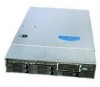
/ SR2625UR. This includes illustrations of the products, a list of the server system features, and diagrams showing the location of important components and connections on the server systems. AF002818 Figure 1. Intel® Server System SR2600UR Intel® Server System SR2600UR/SR2625UR Service Guide 7 - Intel SR2600UR | Service Guide - Page 28
Figure 2. Intel® Server System SR2625UR AF002819 8 Intel® Server System SR2600UR/SR2625UR Service Guide - Intel SR2600UR | Service Guide - Page 29
.htm • Support for 800/1066/1333 MT/s ECC registered (RDIMM) or unbuffered DIMM (UDIMM) DDR3 memory • Twelve DIMMs across six memory channels (three channels per processor) • Intel® 5520 chipset I/O Hub • Intel® 82801Jx I/O Controller Hub Intel® Server System SR2600UR/SR2625UR Service Guide 9 - Intel SR2600UR | Service Guide - Page 30
2.5 inch hard drives or 3.5 inch tape drive • Intel® Embedded Server RAID Technology II with SW RAID levels 0/1/10 • Optional support for SW RAID 5 with activation key • Slimline bay for slimline SATA optical drive • "PCI riser card bracket 10 Intel® Server System SR2600UR/SR2625UR Service Guide - Intel SR2600UR | Service Guide - Page 31
System Identification • Hard Drive Activity Power Supply Fans System Management Intel® Light-Guided diagnostic LEDs: • Fan Fault • DIMM Fault • CPU Fault • 5V-STBY • System Status • System Identification • POST Code Diagnostics Up to two 750-W power supply modules Intel® Server System SR2600URBRP - Intel SR2600UR | Service Guide - Page 32
supply modules) or two 2.5 inch Hard Drives (optional) F. Riser Card Assembly N. Hard Drive Bays G. Integrated Chassis Intrusion Switch O. Slimline Optical Drive Bay H. Processor Air Duct Figure 3. Intel® Server System SR2600UR Components 12 Intel® Server System SR2600UR/SR2625UR Service - Intel SR2600UR | Service Guide - Page 33
L. Flex Bay - Two additional 2.5 Hard Drives or Tape Drive (optional) F. Integrated Chassis Intrusion Switch M. Slimline Optical Drive Bay G. Processor Air Duct N. Hard Drive Bays Figure 4. Intel® Server System SR2625UR Components Intel® Server System SR2600UR/SR2625UR Service Guide 13 - Intel SR2600UR | Service Guide - Page 34
. • Fan Fault LEDs on the passive midplane (in the passive system - see Figure 6) or active midplane (in the active system - see Figure 7) help identify failed and failing fans. The fan fault LEDs turn on (amber) if there is a fan fault. 14 Intel® Server System SR2600UR/SR2625UR Service Guide - Intel SR2600UR | Service Guide - Page 35
Status LED E. CPU 1 Fan Fault LED G. CPU 2 Fan Fault LED I. CPU 2 DIMM Fault LEDs B. System Identification LED D. Memory 1 Fan Fault LED F. CPU 1 DIMM Fault LEDs H. Memory 2 Fan Fault LED J. 5V Standby LED Figure 5. Intel® Light-Guided Diagnostic LEDs - Server Board AF002833 Intel® Server System - Intel SR2600UR | Service Guide - Page 36
Diagnostic LEDs - Passive Midplane D C E B A F AF003042 A. Fan 2 Fault LED C. Fan 4 Fault LED E. Fan 6 Fault LED B. Fan 3 Fault LED D. Fan 5 Fault LED F. Fan 1 Fault LED Figure 7. Intel® Light-Guided Diagnostic LEDs - Active Midplane 16 Intel® Server System SR2600UR/SR2625UR Service Guide - Intel SR2600UR | Service Guide - Page 37
A B AF003002 A. Status LED B. System Identification LED Figure 8. Intel® Light-Guided Diagnostic LEDs - Standard Control Panel Intel® Server System SR2600UR/SR2625UR Service Guide 17 - Intel SR2600UR | Service Guide - Page 38
Server Board Components This section helps you identify the components and connectors on the server board. AB C D E FG EE DD H I CC J BB AA Z Y X W V U T S R QPO K L NM AF002696 18 Intel® Server System SR2600UR/SR2625UR Service Guide - Intel SR2600UR | Service Guide - Page 39
T. Power Supply SMBus Connector W. Low-profile USB Solid State Drive Header Z. SATA RAID 5 Key Header CC. I/O Module Mezzanine Connector 2 C. Intel® RMM3 Header F. System Identification LED I. CPU 1 Fan Header L. Processor 2 Socket O. Bridge Board Connector (Intel® Server Chassis) R. 2x4 Power - Intel SR2600UR | Service Guide - Page 40
Update Mode is enabled. These pins should be jumpered on 1-2 for normal system operation. C. BIOS Default (J1E7) If pins 2-3 are jumpered, the BIOS settings are cleared on the next reset. These pins should be jumpered on 1-2 for normal operation. 20 Intel® Server System SR2600UR/SR2625UR Service - Intel SR2600UR | Service Guide - Page 41
BIOS image. The main system BIOS will not boot. These pins should be jumpered on 1-2 for normal system operation. Figure 10. Configuration Jumpers Front of Intel® Server System SR2600UR Peripheral Devices The Intel® Server System SR2600UR Intel® Server System SR2600UR/SR2625UR Service Guide 21 - Intel SR2600UR | Service Guide - Page 42
Serial ATA (SATA) hot-swap drives. Note: SAS drives are only supported on the Intel® Server System SR2600URLX (active version). The top leftmost drive bay can be converted to be used as a floppy bay. To use the bay for a floppy drive, the AXXUSBFLOPPY accessory kit must be used. For instructions on - Intel SR2600UR | Service Guide - Page 43
network to which it is connected. Blinking green light indicates network activity. Powers on/off the system. If enabled by an ACPI-compliant operating system, this button functions as a Sleep button and puts the system in an ACPI sleep state. Intel® Server System SR2600UR/SR2625UR Service Guide 23 - Intel SR2600UR | Service Guide - Page 44
to the front of the system. The front and rear video ports cannot be used at the same time. Figure 12. Standard Control Panel Intel® Local Control Panel The following diagram shows the features available on the Intel® Local Control Panel. 24 Intel® Server System SR2600UR/SR2625UR Service Guide - Intel SR2600UR | Service Guide - Page 45
indicates a non-critical condition. No light indicates POST is running or the system is off. Continuous green light indicates a link between the system and the network to which it is connected. Blinking green light indicates network activity. Intel® Server System SR2600UR/SR2625UR Service Guide 25 - Intel SR2600UR | Service Guide - Page 46
47. The order numbers for the bezels are: • ADRBEZBLACK: Black bezel for use with the standard control panel. • ADRLCDBEZEL: Black bezel for use with the Intel® Local Control Panel. 26 Intel® Server System SR2600UR/SR2625UR Service Guide - Intel SR2600UR | Service Guide - Page 47
a maximum ambient temperature of 45°C. Note: The Intel® Server System SR2625UR does not support all SAS or Serial ATA (SATA) hard drives. For a web link to a list of supported hard drives, see "Additional Information and Software" on page 4. Intel® Server System SR2600UR/SR2625UR Service Guide 27 - Intel SR2600UR | Service Guide - Page 48
of control panels: • Standard Control Panel • Intel® Local Control Panel Standard Control Panel For information, see "Standard Control Panel" on page 23. Intel® Local Control Panel For information, see "Intel® Local Control Panel" on page 24. 28 Intel® Server System SR2600UR/SR2625UR Service Guide - Intel SR2600UR | Service Guide - Page 49
Power Supply Module G. Intel® I/O Expansion Module (Optional) H. Intel® Remote Management Module NIC (Optional) I. NIC 1 J. NIC 2 K. USB 6 L. USB 5 M. DB-9 Serial B Connector N. Video O. RJ-45 Serial A Connector Figure 15. Server System Back Panel Intel® Server System SR2600UR/SR2625UR Service - Intel SR2600UR | Service Guide - Page 50
Back Panel Connectors A B C D E F A. Mouse C. Serial Port B (RJ-45) E. NIC 2 (10/100/1000 Mb) G. USB Port 6 B. Keyboard D. NIC 1 (10/100/1000 Mb) F. Video H. USB Port 5 Figure 16. Back Panel Connectors AF002879 30 Intel® Server System SR2600UR/SR2625UR Service Guide - Intel SR2600UR | Service Guide - Page 51
Solid Amber Blinking Amber Off Solid Amber Solid Green Description No network connection Network connection in place Transmit/receive activity 10 Mbps connection (if left LED is on or blinking) 100 Mbps connection 1000 Mbps connection Intel® Server System SR2600UR/SR2625UR Service Guide 31 - Intel SR2600UR | Service Guide - Page 52
Connector G. Fan 3 Power Connector H. Fan 1 Power Connector I. Fan 2 Power Connector J. Backplane Connectors Figure 17. Passive Midplane Components Note: SATA connectors 6 and 7 are not used in the Intel® Server System SR2600UR/SR2625UR. 32 Intel® Server System SR2600UR/SR2625UR Service Guide - Intel SR2600UR | Service Guide - Page 53
F. Bridge Board Connector G. Fan 4 Power Connector H. Fan 3 Power Connector I. Fan 1 Power Connector J. Fan 2 Power Connector K. RAID Activation Key Connector L. Backplane Connectors Figure 18. Active SAS/SATA RAID Midplane Components Intel® Server System SR2600UR/SR2625UR Service Guide 33 - Intel SR2600UR | Service Guide - Page 54
connector found on the backplane. A B C D AF000045 A. Slimline Interposer Card Connector B. USB Floppy Connector C. Control Panel Connector D. SAS/SATA Hot-swap Connectors Figure 19. Hot-Swap SAS/SATA Backplane Components (Front View) 34 Intel® Server System SR2600UR/SR2625UR Service Guide - Intel SR2600UR | Service Guide - Page 55
Connector (for sixth hard drive or tape drive or 2.5 inch fixed drives) C. Power Connector B. SAS/SATA Connector (for sixth hard drive D. Midplane Connectors or SATA tape drive) Figure 20. Hot-Swap SAS/SATA Backplane Components (Rear View) Intel® Server System SR2600UR/SR2625UR Service Guide 35 - Intel SR2600UR | Service Guide - Page 56
drives. The following diagrams show the location for each connector found on the backplane. A B AF002788 A. SAS/SATA Hot-swap Connectors B. Slimline Optical Drive Connector Figure 21. Hot-Swap SAS/SATA Backplane Components (Front View) 36 Intel® Server System SR2600UR/SR2625UR Service Guide - Intel SR2600UR | Service Guide - Page 57
or disable "AHCI Mode" or "Configure SATA as RAID". The Intel® Embedded Server RAID Technology II is enabled by the "Configure SATA as RAID" option. The Intel® Embedded Server RAID Technology II feature provides RAID modes 0, 1, and 10. Intel® Server System SR2600UR/SR2625UR Service Guide 37 - Intel SR2600UR | Service Guide - Page 58
rack, the second system in the second position from the bottom, and so on. For instructions on installing your chassis into a rack, see "Removing and Installing from a Rack" on page 42. These instructions are also included in the rail kit. 38 Intel® Server System SR2600UR/SR2625UR Service Guide - Intel SR2600UR | Service Guide - Page 59
working with your server product, pay close attention to the "Safety Information" on page v at the beginning of this manual. Note: Whenever you service the system, you must first power down the server and unplug all peripheral devices and the AC power cord. Tools and Supplies Needed • Phillips - Intel SR2600UR | Service Guide - Page 60
Power to Active Midplane Board O Server Board SATA 5 Connector Legend 4 Begin cable connections at the 3 SATA-0 location. 2 1 0 C Server Board O CPU1 F LK D K J H I N G CPU2 M E Figure 23. Cable Routing AF002993 40 Intel® Server System SR2600UR/SR2625UR Service Guide - Intel SR2600UR | Service Guide - Page 61
Fan Connections Use the figures below to determine the proper fan connections. 3 2 1 AF003109 Figure 24. Connecting the Non-redundant Fan Power Cables to the Passive Midplane Board Intel® Server System SR2600UR/SR2625UR Service Guide 41 - Intel SR2600UR | Service Guide - Page 62
allows you to service the server system while installed in a rack. Note: Follow all safety guidelines while removing a system from a rack to avoid injury. Fixed Bracket Rack Mount Removal 1. Disconnect all cables from the back of the system. 42 Intel® Server System SR2600UR/SR2625UR Service Guide - Intel SR2600UR | Service Guide - Page 63
system LED to properly identify the system you are servicing. 2. Remove screws from the brackets and remove the system from the rack. Fixed Bracket Rack of the chassis 8. Using two screws, attach one nut bar to the inside of the rack post. Do Intel® Server System SR2600UR/SR2625UR Service Guide 43 - Intel SR2600UR | Service Guide - Page 64
each rail. 8. Align the inner rails (attached to the server chassis) with the outer rail assemblies (attached to the rack). 9. Engage the matching rails and slide the server chassis into the rack until the two safety stops lock into position. 44 Intel® Server System SR2600UR/SR2625UR Service Guide - Intel SR2600UR | Service Guide - Page 65
figures. Note the orientation in the figures the control panel is at the right. If you are installing a bezel on your server system, make sure you position it as shown. AF000154 Figure 26. Front Bezel Supporting the Standard Control Panel Intel® Server System SR2600UR/SR2625UR Service Guide 45 - Intel SR2600UR | Service Guide - Page 66
Panel Removing the Front Bezel If your system includes a front bezel, follow these steps to remove the front bezel: 1. Unlock the bezel (if locked). 2. Pull the bezel from the server system. TP02129 Figure 28. Removing the Front Bezel 46 Intel® Server System SR2600UR/SR2625UR Service Guide - Intel SR2600UR | Service Guide - Page 67
: 1. At each end of the bezel, line up the center notch on the bezel with the center guide on the rack handles. 2. Push the bezel onto the front of the server system until it clicks into place. TP02130 Figure 29. Installing the Front Bezel Intel® Server System SR2600UR/SR2625UR Service Guide 47 - Intel SR2600UR | Service Guide - Page 68
is installed (see letter "A" in Figure 30). 2. While holding in the blue button at the top of the server system in (see letter "B" in Figure 30), slide the top cover back until D A C B AF002954 Figure 30. Removing the Server System Cover 48 Intel® Server System SR2600UR/SR2625UR Service Guide - Intel SR2600UR | Service Guide - Page 69
31). 3. (Optional) Insert the safety screw at the center of the top cover (see letter "B" in Figure 31), if required. B A AF002955 Figure 31. Installing the Server System Cover Intel® Server System SR2600UR/SR2625UR Service Guide 49 - Intel SR2600UR | Service Guide - Page 70
in Figure 33). A A Riser Card Connector B AF002967 Figure 32. Removing PCI Riser Assembly from the Server System 4. Do one of the following: - If you need to add or replace a PCI add-in for another procedure, continue with that procedure. 50 Intel® Server System SR2600UR/SR2625UR Service Guide - Intel SR2600UR | Service Guide - Page 71
the server system back panel slots. The riser cards will seat into the matching sockets on the server board. 4. Connect any cables to add-in cards that require them. See your add-in card documentation for information and add-in card requirements. Intel® Server System SR2600UR/SR2625UR Service Guide - Intel SR2600UR | Service Guide - Page 72
B C Riser Card AF003012 Figure 34. Removing the PCI Riser Card from the Server System (Full-height Side) 6. Install the replacement riser card, if desired. For instructions, see "Installing PCI Riser Card into the Server System" on page 53. 52 Intel® Server System SR2600UR/SR2625UR Service Guide - Intel SR2600UR | Service Guide - Page 73
. 8. Install the PCI add-in card(s), if desired. For instructions, see "Installing a PCI Add-in Card" on page 54. 9. Install the PCI riser assembly into the server system. For instructions, see "Installing the PCI Riser Assembly" on page 51. Intel® Server System SR2600UR/SR2625UR Service Guide 53 - Intel SR2600UR | Service Guide - Page 74
clip. Push the blue slide upward and press the clip to lock it into place. 7. Close the front retention clip and push the blue latch forward to lock it into place. Note: Make sure that all empty add-in card slots have filler panels installed. 54 Intel® Server System SR2600UR/SR2625UR Service Guide - Intel SR2600UR | Service Guide - Page 75
riser assembly. For instructions, see "Removing the PCI Riser Assembly" on page 50. 2. Open the rear retention clip by pushing the blue slide upward and server system. For instructions, see "Installing the PCI Riser Assembly" on page 51. Intel® Server System SR2600UR/SR2625UR Service Guide 55 - Intel SR2600UR | Service Guide - Page 76
the PCI riser assembly. For instructions, see "Removing the PCI Riser Assembly" on page 50. 2. Lift the processor air duct from its location over the two processor sockets. AirPDrouccetssor AF002956 Figure 38. Removing the Processor Air Duct 56 Intel® Server System SR2600UR/SR2625UR Service Guide - Intel SR2600UR | Service Guide - Page 77
CPU 2 DIMM slots empty or store extra blanks in the blue DIMM slots. • If you have both processors installed, all blue DIMM slots in CPU 1 and CPU 2 must either regarding memory requirements and options, refer to the following documents: Intel® Server System SR2600UR/SR2625UR Service Guide 57 - Intel SR2600UR | Service Guide - Page 78
• Intel® Server System SR2600UR Technical Product Specification • Intel® Server System SR2625UR Technical Product Specification For a web link to the list of tested DIMMs, see "Additional Information and Software" on page 4. Installing DIMMs To install DIMMs, follow these steps: 1. Remove - Intel SR2600UR | Service Guide - Page 79
. Caution: Protective socket cover needs to be removed for proper cooling of the processor; failure to remove the cover could result in damage to the system. Installing the Processor To install the processor, follow these steps: Intel® Server System SR2600UR/SR2625UR Service Guide 59 - Intel SR2600UR | Service Guide - Page 80
processor air duct. For instructions, see "Removing the Processor Air Duct" on page 56 3. Remove the heatsink, if installed. For instructions, see "Removing the Heatsink" on page 64. 4. Locate the processor processor that will not be replaced. 60 Intel® Server System SR2600UR/SR2625UR Service Guide - Intel SR2600UR | Service Guide - Page 81
Removing the Processor Protective Cover 11. Orient the processor with the socket such that the orientation notches on the processor align with the two orientation posts on the socket, and insert the processor into the socket (see Figure 45). Intel® Server System SR2600UR/SR2625UR Service Guide 61 - Intel SR2600UR | Service Guide - Page 82
You must install the processor before installing the heatsink. For instructions, see "Installing the Processor" on page 59. Caution replacing a processor, make sure there is adequate TIM present on the heatsink to support processor cooling. 62 Intel® Server System SR2600UR/SR2625UR Service Guide - Intel SR2600UR | Service Guide - Page 83
the system. 3. Set the heatsink over the processor, lining up the four captive screws with the four posts surrounding the processor. 4. Flow 1 4 TIM Chassis Front AF002841 Figure 47. Installing the Heatsink (Passive Heatsink Shown) Intel® Server System SR2600UR/SR2625UR Service Guide 63 - Intel SR2600UR | Service Guide - Page 84
to break the seal between the heatsink and the processor. ii. Lift the heatsink from the processor. If it does not pull up easily, twist the heatsink again. Do not force the heatsink from the processor. Doing so could damage the processor. 64 Intel® Server System SR2600UR/SR2625UR Service Guide - Intel SR2600UR | Service Guide - Page 85
41). 6. Open the CPU load plate (see Figure 42). 7. Remove the processor. 8. If you want to replace the processor, see "Installing the Processor" on page 59. Otherwise, install the protective socket cover over the empty processor socket. Intel® Server System SR2600UR/SR2625UR Service Guide 65 - Intel SR2600UR | Service Guide - Page 86
Installing the Small Air Baffle To install the small air baffle, follows these steps: 1. Lower the baffle into the server system and position the baffle over the two standoff locations. 2. Snap the baffle into place as shown in Figure 50. 66 Intel® Server System SR2600UR/SR2625UR Service Guide - Intel SR2600UR | Service Guide - Page 87
fan baffle. Use the instructions in these sections only when it is indicated as necessary for a component installation process. Always operate your server system with the fan baffle in place. The fan up on it (see letter "C" in Figure 51). Intel® Server System SR2600UR/SR2625UR Service Guide 67 - Intel SR2600UR | Service Guide - Page 88
A C B AF003021 Figure 51. Removing the Fan Baffle 68 Intel® Server System SR2600UR/SR2625UR Service Guide - Intel SR2600UR | Service Guide - Page 89
hole in the backplane board (see letter "C" in Figure 52 - the arrow is pointing to the hole in the backplane board). C B A Figure 52. Installing the Fan Baffle Intel® Server System SR2600UR/SR2625UR Service Guide AF003022 69 - Intel SR2600UR | Service Guide - Page 90
. For help in determining where the cables should be routed, see "Cable Routing" on page 40 or the Quick Reference Label that came with your system. 70 Intel® Server System SR2600UR/SR2625UR Service Guide - Intel SR2600UR | Service Guide - Page 91
: The server system does not support all hard drives. For a web link to a list of supported hard drives, see "Additional Information and Software" on page 4. Installing a SAS or SATA Hot-swap Hard Disk Drive To install a SAS or SATA hot-swap hard disk drive in Intel® Server System SR2600UR, follow - Intel SR2600UR | Service Guide - Page 92
antistatic surface. 5. Set any jumpers and/or switches on the drive according to the drive manufacturer's instructions. 6. With the drive circuit-side down, position the connector end of the drive so that it retention device (see Figure 57). 72 Intel® Server System SR2600UR/SR2625UR Service Guide - Intel SR2600UR | Service Guide - Page 93
the server system and push all the way until it stops (see letter "A" in Figure 58). 9. Close the lever to lock the drive assembly into place (see letter "B" in Figure 58). A B AF002946 Figure 58. Install Drive Assembly into the Server System Intel® Server System SR2600UR/SR2625UR Service Guide 73 - Intel SR2600UR | Service Guide - Page 94
link to a list of supported hard drives, see "Additional Information and Software" on page 4. Installing a Hot-swap SAS/SATA Hard Disk Drive To install a hot-swap SAS/SATA hard disk drive in Intel® Server System SR2625UR, follow these steps: 74 Intel® Server System SR2600UR/SR2625UR Service Guide - Intel SR2600UR | Service Guide - Page 95
static surface. 5. Set any jumpers and/or switches on the drive according to the drive manufacturer's instructions. 6. With the drive circuit-side down, position the connector end of the drive so that it device (see letter "B" in Figure 61). Intel® Server System SR2600UR/SR2625UR Service Guide 75 - Intel SR2600UR | Service Guide - Page 96
carrier. 2. Pull out on the black lever to slide the carrier out from the server system. 3. Remove the four screws that attach the hard drive to the drive carrier. Lift the drive from the carrier and store the drive in an anti-static bag. 76 Intel® Server System SR2600UR/SR2625UR Service Guide - Intel SR2600UR | Service Guide - Page 97
proper system cooling, a filler blank must be installed if you do not install a device at this location. Note: The Intel® Server System SR2600UR also supports the installation of a USB floppy in place of the slimline SATA optical device. Intel® Server System SR2600UR/SR2625UR Service Guide 77 - Intel SR2600UR | Service Guide - Page 98
Internal USB Floppy To install a slimline optical drive or internal USB floppy in Intel® Server System SR2600UR, follow these steps: 1. Remove the empty tray and screw from the accessory 64. Installing the Optical Device into the Drive Tray 78 Intel® Server System SR2600UR/SR2625UR Service Guide - Intel SR2600UR | Service Guide - Page 99
system (see letter "A" in Figure 66). 7. Make sure that the back end of the interposer board plugs into the matching socket on the backplane (see letter "B" in Figure 66). 8. Verify that the blue Optical Drive Assembly into the Server System Intel® Server System SR2600UR/SR2625UR Service Guide 79 - Intel SR2600UR | Service Guide - Page 100
or internal USB floppy from Intel® Server System SR2600UR, follow these steps: 1. If removing an internal USB floppy, unplug it from the backplane. 2. Press the blue release lever (see letter "A" "C" in Figure 68) to remove it from the tray. 80 Intel® Server System SR2600UR/SR2625UR Service Guide - Intel SR2600UR | Service Guide - Page 101
5. If no device will be installed in this location, install a filler blank as shown in Figure 69. A AF000155 Figure 69. Installing Filler Blank into the Server System Intel® Server System SR2600UR/SR2625UR Service Guide 81 - Intel SR2600UR | Service Guide - Page 102
Guide to the Optical Drive 2. Insert the optical drive tray assembly into the server system opening and push all the way until it stops (see Figure 66). 3. Make sure that the back end of the device plugs into the matching socket on the backplane. 82 Intel® Server System SR2600UR/SR2625UR Service - Intel SR2600UR | Service Guide - Page 103
from Intel® Server System SR2625UR, follow these steps: 1. Press in on the plastic guide at the rear of the optical drive (see letter "A" in Figure 72) and push forward to unlock and remove the slimline optical drive from the server system. Intel® Server System SR2600UR/SR2625UR Service Guide 83 - Intel SR2600UR | Service Guide - Page 104
Remove the default filler panel from the server system by pressing the blue release lever (see letter "A" in Figure 73) and pushing it forward to release it and then sliding it out from the front of the system (see letter "B" in Figure 73). 84 Intel® Server System SR2600UR/SR2625UR Service Guide - Intel SR2600UR | Service Guide - Page 105
A B AF003029 Figure 73. Removing Tape Drive Filler Panel from the Server System 2. Attach the tape drive to the tape drive carrier kit using the four screws into the combined tape drive bay/sixth drive bay until the carrier clicks into place. Intel® Server System SR2600UR/SR2625UR Service Guide 85 - Intel SR2600UR | Service Guide - Page 106
) kit, order number ASR2500SIXDRV. • You must purchase an additional 3.5 inch hard disk rive. After purchasing the sixth SAS/SATA Hard Disk Drive (HDD)kit and the 3.5 hard disk drive, use the following instructions to install the hard drive. 86 Intel® Server System SR2600UR/SR2625UR Service Guide - Intel SR2600UR | Service Guide - Page 107
from the front of the system (see letter "B" in Figure 76. A B Figure 76. Removing the Filler Panel 2. Install the sixth hard drive filler panel as shown in Figure 77. AF003029 AF003032 Figure 77. Installing Sixth Hard Drive Filler Panel Intel® Server System SR2600UR/SR2625UR Service Guide 87 - Intel SR2600UR | Service Guide - Page 108
(see letter "A" in Figure 79). b. Install one end of the short SATA cable to the SATA connector on the backplane. c. Install the other end of the short SATA cable to the SATA connector on the sixth HDD board (see letter "B" in Figure 79). 88 Intel® Server System SR2600UR/SR2625UR Service Guide - Intel SR2600UR | Service Guide - Page 109
letter "B" in Figure 80) and route the cable through the air baffle (see letter "C" in Figure 80). c. Connect the other end of the cable (labeled SERVER BOARD) to the SATA5 connector on the server board (see letter "D" in Figure 80). Intel® Server System SR2600UR/SR2625UR Service Guide 89 - Intel SR2600UR | Service Guide - Page 110
disk drive kit and the 2.5 inch hard disk drives, use the following instructions to install the 2.5 inch drives. In addition to these instructions, refer to the instructions that came with your 2.5 inch drives for additional requirements. 90 Intel® Server System SR2600UR/SR2625UR Service Guide - Intel SR2600UR | Service Guide - Page 111
from the server system by pressing the blue release lever (see letter "A" in Figure 81) and pushing it forward to release it and then sliding it out from the front of the system (see letter 82. Attaching the 2.5 inch HDDs to the drive cage Intel® Server System SR2600UR/SR2625UR Service Guide 91 - Intel SR2600UR | Service Guide - Page 112
the 2.5 inch fixed hard disk drive kit as shown in Figure 83. A AF003036 Figure 83. Attaching the 2.5 inch HDD assembly to the filler panel 92 Intel® Server System SR2600UR/SR2625UR Service Guide - Intel SR2600UR | Service Guide - Page 113
the power cable to the two hard disk drives (see letter "B" in Figure 85). 7. Connect one end of the data cables to the SATA connectors on the server board (see letter "C" in Figure 85) or SAS/SATA connectors on an SAS/SATA add-in PCI card. Intel® Server System SR2600UR/SR2625UR Service Guide 93 - Intel SR2600UR | Service Guide - Page 114
D C A Figure 85. Installing Power and Data Cables AF003038 Filling Empty Server System Bays (Intel® Server System SR2600UR only) In the Intel® Server System SR2600UR, you must install either a filler bay 4) (see letter "C" in Figure 86). 94 Intel® Server System SR2600UR/SR2625UR Service Guide - Intel SR2600UR | Service Guide - Page 115
the other drive bays, install the drive blank into the hard drive carrier. • Install empty hard drive carriers into any remaining empty hard drive bays. Intel® Server System SR2600UR/SR2625UR Service Guide 95 - Intel SR2600UR | Service Guide - Page 116
processor air duct. For instructions, see "Removing the Processor Air Duct" on page 56. 3. Squeeze the sides of the I/O expansion module filler panel(s) to disengage it from the server system module over the server board as shown in Figure 88. 96 Intel® Server System SR2600UR/SR2625UR Service Guide - Intel SR2600UR | Service Guide - Page 117
3. Disconnect the I/O expansion module from the server board connector and the standoffs and remove the module out of the server system (see letter "A" in Figure 89. 4. Remove the standoffs from the server board (see letter "B" in Figure 89). Intel® Server System SR2600UR/SR2625UR Service Guide 97 - Intel SR2600UR | Service Guide - Page 118
Module 3, follow these steps: 1. Remove the PCI riser assembly. For instructions, see "Removing the PCI Riser Assembly" on page 50. 2. Remove the processor air duct. For instructions, see "Removing the Processor Air Duct" on page 56. 98 Intel® Server System SR2600UR/SR2625UR Service Guide - Intel SR2600UR | Service Guide - Page 119
Top View AF002948 Figure 91. Installing the Intel® RMM3 to the bracket 5. Connect one end of the cable (labeled 'RMM3') to the RMM3 connector on the Intel® RMM3 (see Figure 92). Note: Cable connectors are keyed and can only go in one way. Intel® Server System SR2600UR/SR2625UR Service Guide 99 - Intel SR2600UR | Service Guide - Page 120
System 8. Install the processor air duct. For instructions, see "Installing the Processor Air Duct" on page 57. 9. Install the PCI riser assembly into the server system. For instructions, see "Installing the PCI Riser Assembly" on page 51. 100 Intel® Server System SR2600UR/SR2625UR Service Guide - Intel SR2600UR | Service Guide - Page 121
. For instructions, see "Removing the Processor Air Duct" on page 56. 3. Remove screws from the back of the chassis (see letter "A" in Figure 94). 4. Disconnect the Intel® RMM3 from the connector on the server board (see letter "B" in Figure 94) and remove the module out of the server system (see - Intel SR2600UR | Service Guide - Page 122
instructions, see "Removing the Processor Air Duct" on page 56. 3. Disconnect all cables from the midplane board. 4. Remove the fan baffle. For instructions, see "Removing the Fan Baffle" on page 67. 5. Remove the bridge board as follows: 102 Intel® Server System SR2600UR/SR2625UR Service Guide - Intel SR2600UR | Service Guide - Page 123
the fan module. For instructions, see "Replacing a Fan Module" on page 127. 7. Hold the midplane board only by the edges and slide the midplane board in the direction shown to release it from the backplane (see letter "A" in Figure 97). Intel® Server System SR2600UR/SR2625UR Service Guide 103 - Intel SR2600UR | Service Guide - Page 124
the midplane board over the retention pins (see letter "A" in Figure 98). 2. Align the four holes on the midplane with the four standoffs on the chassis and press down uniformly until it clicks into place (see letter "B" in Figure 98). 104 Intel® Server System SR2600UR/SR2625UR Service Guide - Intel SR2600UR | Service Guide - Page 125
into the backplane connector (see letter "C" in Figure 98). A C B C Figure 98. Installing the Midplane into the Server System 4. Connect cables as necessary to the midplane board. 5. Passive midplane only: Do the following: AF002973 Intel® Server System SR2600UR/SR2625UR Service Guide 105 - Intel SR2600UR | Service Guide - Page 126
(see letter "A" in Figure 100). b. Slide the bridge board through the fan assembly (see letter "B" in Figure 100). c. Insert the bridge board into the bridge board connector on the midplane and server board (see letter "C" in Figure 100). 106 Intel® Server System SR2600UR/SR2625UR Service Guide - Intel SR2600UR | Service Guide - Page 127
these steps: 1. Remove the midplane board. For instructions, see "Removing the Midplane Board" on page 102. Note: To prevent damage to your system, you must ensure the midplane is completely removed before attempting to remove the backplane. Intel® Server System SR2600UR/SR2625UR Service Guide 107 - Intel SR2600UR | Service Guide - Page 128
drive is installed in the carrier. For instructions, see "Removing a SAS or SATA Hot-swap Hard Disk Drive" on page 74. 3. Disconnect all cables from the backplane. 4. Depending on your server system, do one of the following: For Intel® Server System SR2600UR, do the following: - Firmly grasp the top - Intel SR2600UR | Service Guide - Page 129
of whether or not a drive is installed in the carrier. For instructions, see "Removing a SAS or SATA Hot-swap Hard Disk Drive" on page 74. 3. Depending on your server system, do one of the following: For Intel® Server System SR2600UR, do the following: a. Hold the backplane only by the edges. Do - Intel SR2600UR | Service Guide - Page 130
in the server system (see letter "B" in Figure 104). c. Slide the backplane board in the direction shown to lock it in place (see letter "C" in Figure 104). d. Secure the backplane with the blue thumscrew (see letter "D" in Figure 104). 110 Intel® Server System SR2600UR/SR2625UR Service Guide - Intel SR2600UR | Service Guide - Page 131
Only) Installing the RAID Activation Key and the RAID Mini-DIMM To install the RAID activation key and RAID Mini-DIMM, follow these steps: 1. Remove the PCI riser assembly. For instructions, see "Removing the PCI Riser Assembly" on page 50. Intel® Server System SR2600UR/SR2625UR Service Guide 111 - Intel SR2600UR | Service Guide - Page 132
page 51. Removing the RAID Activation Key and the RAID Mini-DIMM To remove the RAID activation key and RAID Mini-DIMM, follow these steps: 1. Remove the PCI riser assembly. For instructions, see "Removing the PCI Riser Assembly" on page 50. 112 Intel® Server System SR2600UR/SR2625UR Service Guide - Intel SR2600UR | Service Guide - Page 133
Large Air Baffle" on page 70. 7. Install the processor air duct. For instructions, see "Installing the Processor Air Duct" on page 57. 8. Install the PCI riser assembly. For instructions, see "Installing the PCI Riser Assembly" on page 51. Intel® Server System SR2600UR/SR2625UR Service Guide 113 - Intel SR2600UR | Service Guide - Page 134
the matching chassis tabs and slide towards the power supply until it locks into place (see letter "C" in Figure 107). 7. Connect the cable from the rear of the RAID battery backup unit to the midplane board (see letter "D" in Figure 107). 114 Intel® Server System SR2600UR/SR2625UR Service Guide - Intel SR2600UR | Service Guide - Page 135
the cable from the rear of the RAID battery backup unit and the midplane board (see letter "A" in Figure 108). 5. Slide the RAID battery backup unit away from the power supply and lift from the server system (see letter "B" in Figure 108). Intel® Server System SR2600UR/SR2625UR Service Guide 115 - Intel SR2600UR | Service Guide - Page 136
Air Baffle" on page 70. 5. Remove the fan module assembly. For instructions, see "Replacing a Fan Module" on page 127. 6. Remove the I/O expansion module, if installed. For instructions, see "Removing the I/O Expansion Module" on page 97. 116 Intel® Server System SR2600UR/SR2625UR Service Guide - Intel SR2600UR | Service Guide - Page 137
) and lift the server board from the server system (see letter "B" in Figure 109). A B AF002980 Figure 109. Removing the Server Board 12. Install the replacement server board. For instructions, see "Installing the Server Board" on page 118. Intel® Server System SR2600UR/SR2625UR Service Guide 117 - Intel SR2600UR | Service Guide - Page 138
a Fan Module" on page 127. 8. Install the large air baffle. For instructions, see "Installing the Large Air Baffle" on page 70. 9. Install the bridge board. For instructions, see step 6 in "Installing the Midplane Board" on page 104. 118 Intel® Server System SR2600UR/SR2625UR Service Guide - Intel SR2600UR | Service Guide - Page 139
" on page 56. 3. Locate the battery on the server board (see Figure 111). 4. Insert the tip of a small flat bladed screwdriver, or an equivalent, under the tab in the plastic retainer. Gently push down on the screwdriver to lift the battery. Intel® Server System SR2600UR/SR2625UR Service Guide 119 - Intel SR2600UR | Service Guide - Page 140
, and unplug the AC power cord from the system or wall outlet. The power supply can be replaced if it fails or if one of the fans that is integrated into it fails. To replace the power supply, follow these steps: 1. Do one of the following: 120 Intel® Server System SR2600UR/SR2625UR Service Guide - Intel SR2600UR | Service Guide - Page 141
the Server System 2. Do one of the following: - Insert the replacement power supply module into the power supply cage and push all the way until it clicks into place. AF000024 Figure 114. Installing Power Supply Module into the Server System Intel® Server System SR2600UR/SR2625UR Service Guide - Intel SR2600UR | Service Guide - Page 142
the server board, backplane, and midplane. 6. Remove the hot-swap power supply/supplies. For instructions, see step 1 in "Replacing the Power Supply" on page 120. 7. Remove the two screws to release the module (see letter "A" in Figure 116). 122 Intel® Server System SR2600UR/SR2625UR Service Guide - Intel SR2600UR | Service Guide - Page 143
Large Air Baffle" on page 70. 14. Install the processor air duct. For instructions, see "Installing the Processor Air Duct" on page 57. 15. Install the PCI riser assembly. For instructions, see "Installing the PCI Riser Assembly" on page 51. Intel® Server System SR2600UR/SR2625UR Service Guide 123 - Intel SR2600UR | Service Guide - Page 144
AF002983 Figure 117. Removing Standard Control Panel Module from the Server System 3. Slide the replacement control panel into the server system (see letter "A" in Figure 118) until it clicks into place (see letter "B" in Figure 118). 124 Intel® Server System SR2600UR/SR2625UR Service Guide - Intel SR2600UR | Service Guide - Page 145
server out of service, turn off all peripheral devices connected to the system, turn off the system by pressing the power button, and unplug the AC power cord from the system or to release it from the system (see letter "A" in Figure 119). Intel® Server System SR2600UR/SR2625UR Service Guide 125 - Intel SR2600UR | Service Guide - Page 146
in Figure 120). Data Cable A USB Cable ControlLPoacnael l B AF003015 Figure 120. Connecting the Control Panel Cables 6. Slide the replacement control panel into the server system (see letter "A" in Figure 121) until it clicks into place. 126 Intel® Server System SR2600UR/SR2625UR Service Guide - Intel SR2600UR | Service Guide - Page 147
70. 4. Remove the fan baffle. For instructions, see "Removing the Fan Baffle" on page 67. 5. Remove the bridge board. For instructions, see step 5 in "Removing the Midplane Board" on page 102. 6. Disconnect the fan cables from the midplane. Intel® Server System SR2600UR/SR2625UR Service Guide 127 - Intel SR2600UR | Service Guide - Page 148
fan module assembly as follows: a. Lower the fan assembly into the chassis (see letter "A" in Figure 123). b. Line up the pins on the chassis floor with the matching holes on the bottom of the fan assembly (see letter "B" in Figure 123). 128 Intel® Server System SR2600UR/SR2625UR Service Guide - Intel SR2600UR | Service Guide - Page 149
cables through the air baffle as necessary. 12. Install the fan baffle. For instructions, see "Installing the Fan Baffle" on page 69. 13. Install the processor air duct. For instructions, see "Installing the Processor Air Duct" on page 57. Intel® Server System SR2600UR/SR2625UR Service Guide 129 - Intel SR2600UR | Service Guide - Page 150
70. 4. Remove the fan baffle. For instructions, see "Removing the Fan Baffle" on page 67. 5. Remove the bridge board. For instructions, see step 5 in "Removing the Midplane Board" on page 102. 6. Disconnect the fan cables from the midplane. 130 Intel® Server System SR2600UR/SR2625UR Service Guide - Intel SR2600UR | Service Guide - Page 151
fan module assembly as follows: a. Lower the fan assembly into the chassis (see letter "A" in Figure 125). b. Line up the pins on the chassis floor with the matching holes on the bottom of the fan assembly (see letter "B" in Figure 125). Intel® Server System SR2600UR/SR2625UR Service Guide - Intel SR2600UR | Service Guide - Page 152
"Installing the Large Air Baffle" on page 70. 12. Install the fan baffle. For instructions, see "Installing the Fan Baffle" on page 69. 13. Install the processor air duct. For instructions, see "Installing the Processor Air Duct" on page 57. 132 Intel® Server System SR2600UR/SR2625UR Service Guide - Intel SR2600UR | Service Guide - Page 153
fan and lift straight up to remove it from the module (see Figure 126). 6 LX 5 4 3 2 1 Figure 126. Removing a Fan from the Redundant Fan Module 2. Position the replacement fan so the connector on the fan is at the right and pointing down. Intel® Server System SR2600UR/SR2625UR Service Guide - Intel SR2600UR | Service Guide - Page 154
replaced separately. If one of the fans in the power supply fails, the power supply must be replaced. The system fans at the front of the server system can be individually replaced if one of them fails. To replace a fan, follow these steps: 134 Intel® Server System SR2600UR/SR2625UR Service Guide - Intel SR2600UR | Service Guide - Page 155
the fan from the fan module (see letter "B" in Figure 128). 3 2 2A 1 B A AF003027 Figure 128. Removing a Fan from the Fixed Fan Module 4. Position the replacement fan so the connector on the fan is at the right and pointing down. Intel® Server System SR2600UR/SR2625UR Service Guide 135 - Intel SR2600UR | Service Guide - Page 156
page 130. Installing and Removing the Rack Handles Installing the Rack Handles Align the rack handle with the two holes on the side of the server system and attach the rack handle to the server system with two screws as shown in Figure 130. 136 Intel® Server System SR2600UR/SR2625UR Service Guide - Intel SR2600UR | Service Guide - Page 157
Figure 130. Installing the Rack Handle Removing the Rack Handles Remove the two screws holding the rack handle in place, and remove the rack handle from the server system as shown in Figure 131. AF000020 Figure 131. Removing the Rack Handle Intel® Server System SR2600UR/SR2625UR Service Guide 137 - Intel SR2600UR | Service Guide - Page 158
138 Intel® Server System SR2600UR/SR2625UR Service Guide - Intel SR2600UR | Service Guide - Page 159
options, which is used to change server configuration defaults. You can run the BIOS Setup with or without an operating system being present. For information about specific BIOS setup screens, see the Intel® Server Board S5520UR Technical Product Specification. For a web link to this document - Intel SR2600UR | Service Guide - Page 160
their default values. If "No" is selected and the key is pressed, or if the key is pressed, you are returned to the screen you were in before was pressed without affecting any existing field values. 140 Intel® Server System SR2600UR/SR2625UR Service Guide - Intel SR2600UR | Service Guide - Page 161
to necessary software and instructions. Recording the Current BIOS Settings 1. Boot the computer and press when you see the message: Press Key if you want to run SETUP 2. Write down the current settings in the BIOS Setup program. Intel® Server System SR2600UR/SR2625UR Service Guide 141 - Intel SR2600UR | Service Guide - Page 162
jumper from the normal operation position, that is, Password Clear Protect position (covering pins 1 and 2) to the Password Clear Erase position (covering pins 2 and 3). 142 Intel® Server System SR2600UR/SR2625UR Service Guide - Intel SR2600UR | Service Guide - Page 163
seconds. 6. Move the Password Clear jumper back to the Password Clear Protect position (covering pins 1 and 2). 7. Close the server system. 8. Power up the server. The password is now cleared and can be reset by going into the BIOS setup. Intel® Server System SR2600UR/SR2625UR Service Guide 143 - Intel SR2600UR | Service Guide - Page 164
Default J1E7 Normal 2 Set 3 Default AF003113 Figure 133. BIOS Default Jumper 5. Wait five seconds. 6. Return the BIOS Default jumper to the normal position (covering pins 1 and 2). 7. Close the server system. 8. Power up the system. 144 Intel® Server System SR2600UR/SR2625UR Service Guide - Intel SR2600UR | Service Guide - Page 165
The BIOS defaults settings are now restored and can be reset by going into the BIOS setup. Intel® Server System SR2600UR/SR2625UR Service Guide 145 - Intel SR2600UR | Service Guide - Page 166
146 Intel® Server System SR2600UR/SR2625UR Service Guide - Intel SR2600UR | Service Guide - Page 167
wattage of 750 Watts Table 5. Power Supply Output Capability Voltage +3.3 V +5.0 V +12.0 V1 +12.0 V2 Minimum OCP Limits Maximum OCP Limits 110% (= 26.4 A) 150% (= 36 A) 110% (= 33 A) 150% (= 45 A) 26.0 A 32 A max 26.0 A 32 A max Intel® Server System SR2600UR/SR2625UR Service Guide 147 - Intel SR2600UR | Service Guide - Page 168
625 A) 400% (= 2.0 A) Warning: Do not exceed a combined power output of 90 Watts for the +5 V and +3.3 V outputs. Exceeding a combined 90 Watts will overload the power subsystem and may cause the power supplies to overheat and malfunction. 148 Intel® Server System SR2600UR/SR2625UR Service Guide - Intel SR2600UR | Service Guide - Page 169
change 136 inches/sec. 5 Hz to 500 Hz, 2.20 g RMS random. Sound Power: 7.0 BA in an idle state at typical office ambient temperature (23 +/- 2°C). +/-12 KV except I/O port +/- 8 KV per Intel Environment test specification. 2550 BTU/Hr Intel® Server System SR2600UR/SR2625UR Service Guide 149 - Intel SR2600UR | Service Guide - Page 170
150 Intel® Server System SR2600UR/SR2625UR Service Guide - Intel SR2600UR | Service Guide - Page 171
System BIOS Version: Intel® Remote Management Module Firmware Version (if applicable): Intel® Management Module BMC Revision (if applicable) : BMC/mBMC Version: FRU/SDR Version: HSC Version: Has the latest BIOS been tried? (Yes/No): Intel® Server System SR2600UR/SR2625UR Service Guide 151 - Intel SR2600UR | Service Guide - Page 172
1 Processor 2 Processor 3 Processor 4 Type Speed sSpec Thermal Solution Thermal solution (Heatsink) examples: (1U, Passive w/air ducting, Active w/fan, etc Memory: Manufacturer Part Number DRAM Part Number On Intel tested list? 152 Intel® Server System SR2600UR/SR2625UR Service Guide - Intel SR2600UR | Service Guide - Page 173
(Example: RedHat* Enterprise Linux, Microsoft* Windows* Server 2003, Service pack 1, OEM CD): Manufacturer: Version: Language version (English, Arabic, Chinese (Simplified)): Service Pack Level or Kernel Revision: Distribution (OEM/Retail Intel® Server System SR2600UR/SR2625UR Service Guide 153 - Intel SR2600UR | Service Guide - Page 174
RAID driver been tried? (Yes/No): RAID volumes configuration (disks & RAID level): RAID volume use (Boot device/Data Volume): Is BBU (Battery Backup Unit) installed? (Yes/No): BBU part number Detailed description of issue: Troubleshooting tried: 154 Intel® Server System SR2600UR/SR2625UR Service - Intel SR2600UR | Service Guide - Page 175
a brief description below. Have you returned systems or components to your place of purchase because of this issue? If yes, please provide a brief description below. *All other brands and names are property of their respective owners. Intel® Server System SR2600UR/SR2625UR Service Guide 155 - Intel SR2600UR | Service Guide - Page 176
156 Intel® Server System SR2600UR/SR2625UR Service Guide - Intel SR2600UR | Service Guide - Page 177
7. POST Progress Code LED Example Upper Nibble LEDs MSB LED #7 LED #6 LED #5 LED #4 8h 4h 2h 1h ON OFF ON OFF LED #3 8h ON Lower Nibble LEDs LSB LED #2 LED #1 LED #0 4h 2h 1h ON OFF OFF 1 0 1 0 1 1 0 0 Ah Ch Intel® Server System SR2600UR/SR2625UR Service Guide 157 - Intel SR2600UR | Service Guide - Page 178
mode No Usable Memory Error: No memory in the system, or SPD bad so no memory could be detected Channel Training Error: DQ/DQS training failed on a channel during memory channel initialization. Memory Test Error: memory failed Hardware BIST. 158 Intel® Server System SR2600UR/SR2625UR Service Guide - Intel SR2600UR | Service Guide - Page 179
O X XXX Power-on initialization of the host processor (bootstrap processor) X X OX XXO Host processor cache initialization (including AP) X X O X X OX Starting application processor initialization X X OX X OO SMM initialization Intel® Server System SR2600UR/SR2625UR Service Guide 159 - Intel SR2600UR | Service Guide - Page 180
LED #7 #6 #5 #4 #3 #2 #1 #0 Chipset 0x21h X X O X X XXO Initializing a chipset component Memory 0x22h 0x23h 0x24h 0x25h 0x26h 0x27h 0x28h X X O X X X OX Reading configuration data from memory O O XXO Reserved for USB devices 160 Intel® Server System SR2600UR/SR2625UR Service Guide - Intel SR2600UR | Service Guide - Page 181
MSB Lower Nibble LSB Description 8h 4h 2h 1h 8h 4h 2h 1h LED #7 #6 #5 #4 #3 #2 #1 #0 ATA / ATAPI / SATA 0x5Ah X 0x5Bh X SMBUS 0x5Ch X 0x5Dh X Local Console 0x70h X Instructing keyboard controller to run Self Test (PS2 only) Intel® Server System SR2600UR/SR2625UR Service Guide - Intel SR2600UR | Service Guide - Page 182
Upper Nibble MSB Lower Nibble LSB Description 8h 4h 2h 1h 8h 4h 2h 1h LED 0x98h 0x99h 0x9Ah 0x9Bh #7 #6 #5 #4 #3 #2 #1 #0 O X drive detection, etc.) X O OX X OO Enabling / configuring a fixed media device X O O O XXX Resetting Intel® Server System SR2600UR/SR2625UR Service Guide - Intel SR2600UR | Service Guide - Page 183
beep code) 0xE4h O O O X X OX X Entered EFI driver execution (DXE) phase 0xE5h O OOX X OX O Started dispatching drivers 0xE6h O O O X X OOX Started connecting drivers DXE Drivers 0xE7h O OOX O OX O Waiting for user input Intel® Server System SR2600UR/SR2625UR Service Guide 163 - Intel SR2600UR | Service Guide - Page 184
has been initiated because of a user request Crisis recovery has been initiated by software (corrupt flash) Loading crisis recovery capsule Handing off control to the crisis recovery capsule Unable to complete crisis recovery capsule 164 Intel® Server System SR2600UR/SR2625UR Service Guide - Intel SR2600UR | Service Guide - Page 185
Latest BIOS, firmware, drivers and utilities - Product documentation, installation and quick start guides - Full product specifications, technical advisories and errata - Compatibility documentation for memory, hardware add-in cards, chassis support matrix and operating systems - Server and chassis - Intel SR2600UR | Service Guide - Page 186
166 Intel® Server System SR2600UR/SR2625UR Service Guide - Intel SR2600UR | Service Guide - Page 187
the server system, power supply, and other modules have passed EMC testing using a server board with a microprocessor from the same family (or higher) and operating at the same (or higher) speed as the microprocessor used on this server board. The final configuration of your end system product may - Intel SR2600UR | Service Guide - Page 188
EEE (Europe) • IRAM Certification (Argentina) • GB4943- CNCA Certification (China) Product EMC Compliance - Class A Compliance • FCC /ICES-003 - Emissions (USA/ - CNCA Certification (China) • GB 17625 - (Harmonics) CNCA Certification (China) 168 Intel® Server System SR2600UR/SR2625UR Service Guide - Intel SR2600UR | Service Guide - Page 189
Data Sheet is available for Intel products. For more reference on material restrictions and compliance you can view Intel's Environmental Product Content Specification at http://supplier.intel Use Period • Packaging & Product Recycling Marks Intel® Server System SR2600UR/SR2625UR Service Guide 169 - Intel SR2600UR | Service Guide - Page 190
9. Product Regulatory Compliance Markings Regulatory Compliance cULus Listing Marks Country USA/Canada Marking GS Mark Germany CE Mark Europe FCC Marking (Class A) USA EMC Marking (Class A) Canada VCCI Marking (Class A) Japan 170 Intel® Server System SR2600UR/SR2625UR Service Guide - Intel SR2600UR | Service Guide - Page 191
Table 9. Product Regulatory Compliance Markings Regulatory Compliance BSMI Certification Number & Class A Warning Country Taiwan Marking Safety Compliance Mark Belarus Waste of Electronic and Electrical Equipment Recycling Mark Europe Intel® Server System SR2600UR/SR2625UR Service Guide 171 - Intel SR2600UR | Service Guide - Page 192
/ perchlorate This notice is required by California Code of Regulations, Title 22, Division 4.5, and Chapter 33: Best Management Practices for Perchlorate Materials. This product may include a battery which contains Perchlorate material. 172 Intel® Server System SR2600UR/SR2625UR Service Guide - Intel SR2600UR | Service Guide - Page 193
skall anslutas till jordat uttag, när den ansluts till ett nätverk." "Laite on liitettävä suojamaadoituskoskettimilla varustettuun pistorasiaan." "Connect only to a properly earth grounded outlet." Stand-by power Intel® Server System SR2600UR/SR2625UR Service Guide 173 - Intel SR2600UR | Service Guide - Page 194
. If the power system for the equipment rack is installed on a branch circuit with more than 20 amperes of protection, you must provide supplemental protection for the server. If DC power supplies are installed: Connection with a DC (Direct Current) source should only be performed by trained service - Intel SR2600UR | Service Guide - Page 195
that plug into the AC receptacle on the server must be an approved IEC (International Electrotechnical Commission) 320, sheet C13, type female connector. • Cord length and flexibility: Cords must be less than 4.5 meters (14.76 feet) long. Intel® Server System SR2600UR/SR2625UR Service Guide 175 - Intel SR2600UR | Service Guide - Page 196
may cause undesired operation. For questions related to the EMC performance of this product, contact: Intel Corporation 5200 N.E. Elam Young Parkway Hillsboro, OR 97124-6497 1-800-628-8686 may result in interference to radio and TV reception. 176 Intel® Server System SR2600UR/SR2625UR Service Guide - Intel SR2600UR | Service Guide - Page 197
does not exceed the Class A limits for radio noise emissions from digital apparatus set out in the interference- instruction manual. BSMI (Taiwan) The BSMI Certification Marking and EMC warning is located on the outside rear area of the product. Intel® Server System SR2600UR/SR2625UR Service Guide - Intel SR2600UR | Service Guide - Page 198
Storage Devices: must be UL recognized or UL listed accessory and TUV or VDE Certificationd. Maximum power rating of any one device is 19 watts. Total server configuration is not to exceed the maximum loading conditions of the power supply. 178 Intel® Server System SR2600UR/SR2625UR Service Guide - Intel SR2600UR | Service Guide - Page 199
Appendix F: Installation/Assembly Safety Instructions English The power supply in this product contains no user-serviceable parts. There may be more than one supply in this product. Refer servicing only to qualified personnel. Do not attempt to modify or use the supplied AC power cord if it is not - Intel SR2600UR | Service Guide - Page 200
chassis covers before turning on the system. Operating the system without the covers in place can damage system parts manufacturer's instructions. The system is power supply cord(s), because they serve as the product's main power disconnect. 180 Intel® Server System SR2600UR/SR2625UR Service Guide - Intel SR2600UR | Service Guide - Page 201
. 5. Tragen Sie ein geerdetes Antistatik Gelenkband, um elektrostatische Ladungen (ESD) über blanke Metallstellen bei der Handhabung der Komponenten zu vermeiden. 6. Schalten Sie das System niemals ohne ordnungsgemäß montiertes Gehäuse ein. Intel® Server System SR2600UR/SR2625UR Service Guide 181 - Intel SR2600UR | Service Guide - Page 202
anzubringen: 1. Vergewissern Sie sich, daß Sie keine Werkzeuge oder Teile im Innern des Systems zurückgelassen haben. 2. Überprüfen Sie alle Kabel, Zusatzkarten und andere Komponenten Batterien den Anweisungen des Herstellers entsprechend. 182 Intel® Server System SR2600UR/SR2625UR Service Guide - Intel SR2600UR | Service Guide - Page 203
Français Das System wurde für den Betrieb in einer normalen Büroumgebung entwickelt. Der Standort sollte: • "sauber und staubfrei sein ( le système est branché doit se situer à proximité de l'équipement et être facilement accessible. Intel® Server System SR2600UR/SR2625UR Service Guide 183 - Intel SR2600UR | Service Guide - Page 204
a été sous tension. Faites également attention aux broches aiguës des cartes et aux bords tranchants du capot. Nous vous recommandons l'usage de gants de protection. 184 Intel® Server System SR2600UR/SR2625UR Service Guide - Intel SR2600UR | Service Guide - Page 205
type ou d'un type équivalent recommandé par le fabricant. Disposez des piles usées selon les instructions du fabricant. Le système a été conçu pour fonctionner dans un cadre de travail normal. ón de corriente alterna que tenga el producto Intel® Server System SR2600UR/SR2625UR Service Guide 185 - Intel SR2600UR | Service Guide - Page 206
las tapas del sistema. Para ello: 1. Desbloquee y extraiga el bloqueo de seguridad de la parte posterior del sistema, si se ha instalado uno. 2. Extraiga y guarde todos los tornillos de externos y los cables de alimentación CA al sistema. 186 Intel® Server System SR2600UR/SR2625UR Service Guide - Intel SR2600UR | Service Guide - Page 207
ñado para funcionar en un entorno de trabajo normal. Escoja un lugar: • "Limpio y libre de partículas en suspensión (salvo el polvo normal). • "Bien ventilado y alejado de fuentes de calor, il prodotto disponga di più fonti di alimentazione. Intel® Server System SR2600UR/SR2625UR Service Guide 187 - Intel SR2600UR | Service Guide - Page 208
e chiudere a chiave il lucchetto sul retro del sistema per impedire l'accesso non autorizzato al sistema. 5. Ricollegare tutti i cavi esterni e le prolunghe AC del sistema. 188 Intel® Server System SR2600UR/SR2625UR Service Guide - Intel SR2600UR | Service Guide - Page 209
Scegliere una postazione che sia: • "Pulita e libera da particelle in sospensione (a parte la normale polvere presente nell'ambiente). • "Ben ventilata e lontana da fonti di calore il mezzo principale di scollegamento del sistema. Intel® Server System SR2600UR/SR2625UR Service Guide 189 - Intel SR2600UR | Service Guide - Page 210
190 Intel® Server System SR2600UR/SR2625UR Service Guide - Intel SR2600UR | Service Guide - Page 211
if the WARNING is ignored. Indicates potential hazard if indicated information is ignored. Indicates shock hazards that result in serious injury or death if safety instructions are not followed. Indicates hot components or surfaces. Intel® Server System SR2600UR/SR2625UR Service Guide 191 - Intel SR2600UR | Service Guide - Page 212
. • Use mechanical assistance or other suitable assistance when moving and lifting equipment. • To reduce the weight for easier handling, remove any easily detachable components. 192 Intel® Server System SR2600UR/SR2625UR Service Guide - Intel SR2600UR | Service Guide - Page 213
for each system power supply. Some power supplies in Intel® servers use Neutral Pole Fusing. To avoid risk of shock use caution when working with power supplies that use Neutral Pole Fusing. The power supply in this product contains no user-serviceable parts. Do not open the power supply. Hazardous - Intel SR2600UR | Service Guide - Page 214
, and it must be labeled as controlling power to the entire unit, not just to the server(s). To avoid risk of potential electric shock, a proper safety ground must be implemented for the rack and each piece of equipment installed in it. 194 Intel® Server System SR2600UR/SR2625UR Service Guide - Intel SR2600UR | Service Guide - Page 215
parts inside the system. • Check that cables, add-in boards, and other components are properly installed. • Attach the covers to the chassis according to the product instructions are not user serviceable • Return to manufacturer for servicing Intel® Server System SR2600UR/SR2625UR Service Guide 195 - Intel SR2600UR | Service Guide - Page 216
Deutsch Sicherheitshinweise für den Server Das vorliegende Dokument bezieht sich auf Intel® Serverplatinen, Intel® Servergehäuse (Standfuß und Rack) sowie installierte Peripheriegeräte an heißen Bauteilen bzw. Oberflächen hin. 196 Intel® Server System SR2600UR/SR2625UR Service Guide - Intel SR2600UR | Service Guide - Page 217
äte erzeugt werden. • In gewittergefährdeten Gebieten sollten Sie das System an einen Überspannungsschutz anschließen und bei einem Gewitter die Telekommunikationskabel lassen, um das Gewicht zu reduzieren und die Handhabung zu erleichtern. Intel® Server System SR2600UR/SR2625UR Service Guide 197 - Intel SR2600UR | Service Guide - Page 218
vom Stromnetz. Die Steckdose muß in der Nähe der Anlage angebracht und gut erreichbar sein. • Netzkabel müssen an eine ordnungsgemäß geerdete Steckdose angeschlossen sein. 198 Intel® Server System SR2600UR/SR2625UR Service Guide - Intel SR2600UR | Service Guide - Page 219
beachtet werden. Gehen Sie bei der Installation von Geräten im Rack immer von unten nach oben vor, und bauen Sie das schwerste Gerät an der untersten Position im Rack ein. Ziehen Sie jeweils immer nur ein Gerät aus dem Rack heraus. Intel® Server System SR2600UR/SR2625UR Service Guide 199 - Intel SR2600UR | Service Guide - Page 220
müssen das Rack selbst und Systems ohne Abdeckung kann zur Beschädigung von Systemkomponenten führen. So bringen Sie die Abdeckung wieder an: • Vergewissern Sie sich zunächst, daß Sie keine Werkzeuge oder Teile im Gehäuse vergessen haben. 200 Intel® Server System SR2600UR/SR2625UR Service Guide - Intel SR2600UR | Service Guide - Page 221
Ce document s'applique aux cartes serveur Intel®, au châssis de serveur Intel® (sur pieds et sur rack) et aux périphériques install Vous devez suivre les informations de ce guide et les instructions d'assemblage des manuels de serveur pour vé Intel® Server System SR2600UR/SR2625UR Service Guide 201 - Intel SR2600UR | Service Guide - Page 222
soleil et les radiateurs. • À l'écart des sources de vibration ou des chocs physiques. • Isolé des champs électromagnétiques importants produits par des appareils électriques. 202 Intel® Server System SR2600UR/SR2625UR Service Guide - Intel SR2600UR | Service Guide - Page 223
ou de supprimer un composant non connectable à chaud. Les alimentations de certains serveurs Intel sont munies de doubles fusibles pôle/neutre: veuillez observer les précautions d'usage alimentation. L'intérieur de celui-ci est soumis à des Intel® Server System SR2600UR/SR2625UR Service Guide 203 - Intel SR2600UR | Service Guide - Page 224
Les cordons d'alimentation doivent répondre aux critères suivants : - Le cordon d'alimentation doit supporter une intensité supérieure à celle indiquée sur le produit. - Le cordon d'alimentation communication qui sont connectés au système. 204 Intel® Server System SR2600UR/SR2625UR Service Guide - Intel SR2600UR | Service Guide - Page 225
et doit être étiqueté comme contrôlant toute l'unité, et pas uniquement le ou les serveurs. Pour éviter tout risque d'électrocution, le rack et chaque élément de l'équipement installé dans le rack doivent être correctement reliés à la terre. Intel® Server System SR2600UR/SR2625UR Service Guide 205 - Intel SR2600UR | Service Guide - Page 226
système. • Vérifiez que les câbles, les cartes d'extension et les autres composants sont correctement installés. • Fixez les panneaux au châssis en suivant les instructions du produit. 206 Intel® Server System SR2600UR/SR2625UR Service Guide - Intel SR2600UR | Service Guide - Page 227
irse a las directrices de esta guía y a las instrucciones de montaje de los manuales del servidor para asegurar y mantener el cumplimiento con las certificaciones y homologaciones existentes de graves si no se tiene en cuenta la ADVERTENCIA. Intel® Server System SR2600UR/SR2625UR Service Guide 207 - Intel SR2600UR | Service Guide - Page 228
conectada a tierra. • Provista de espacio suficiente para acceder a los cables de la fuente de alimentación ya que constituyen la desconexión principal de la alimentación. 208 Intel® Server System SR2600UR/SR2625UR Service Guide - Intel SR2600UR | Service Guide - Page 229
conexión en funcionamiento. Algunas fuentes de alimentación de electricidad de los servidores de Intel utilizan el polo neutral del fuselaje. Para evitar riesgos de choques electricos use adquiera alguno cuyo uso esté aprobado en su país. Intel® Server System SR2600UR/SR2625UR Service Guide 209 - Intel SR2600UR | Service Guide - Page 230
para repararla. • Apague el servidor y desconecte todos los cables de alimentación antes de agregar o reemplazar cualquier componente que no es de conexión en funcionamiento. 210 Intel® Server System SR2600UR/SR2625UR Service Guide - Intel SR2600UR | Service Guide - Page 231
del bastidor. Instale el equipo en el bastidor comenzando desde la parte de abajo, con el equipo más pesado en la parte inferior del bastidor. Extraiga las piezas del equipo del bastidor de electrostáticas. En caso de que no haya una Intel® Server System SR2600UR/SR2625UR Service Guide 211 - Intel SR2600UR | Service Guide - Page 232
dentro del sistema. • Compruebe que los cables, tarjetas adicionales y otros componentes están instalados correctamente. • Sujete las cubiertas a la carcasa siguiendo las instrucciones del producto. 212 Intel® Server System SR2600UR/SR2625UR Service Guide - Intel SR2600UR | Service Guide - Page 233
caja de ningún periférico o dispositivo láser • Los periféricos o dispositivos láser no pueden ser reparados por el usuario • Haga que el fabricante los repare Intel® Server System SR2600UR/SR2625UR Service Guide 213 - Intel SR2600UR | Service Guide - Page 234
214 Intel® Server System SR2600UR/SR2625UR Service Guide
-
 1
1 -
 2
2 -
 3
3 -
 4
4 -
 5
5 -
 6
6 -
 7
7 -
8
-
9
-
10
-
11
-
12
-
13
-
14
-
15
-
16
-
17
-
18
-
19
-
20
-
21
-
22
-
23
-
24
-
25
-
26
-
27
-
28
-
29
-
30
-
31
-
32
-
33
-
34
-
35
-
36
-
37
-
38
-
39
-
40
-
41
-
42
-
43
-
44
-
45
-
46
-
47
-
48
-
49
-
50
-
51
-
52
-
53
-
54
-
55
-
56
-
57
-
58
-
59
-
60
-
61
-
62
-
63
-
64
-
65
-
66
-
67
-
68
-
69
-
70
-
71
-
72
-
73
-
74
-
75
-
76
-
77
-
78
-
79
-
80
-
81
-
82
-
83
-
84
-
85
-
86
-
87
-
88
-
89
-
90
-
91
-
92
-
93
-
94
-
95
-
96
-
97
-
98
-
99
-
100
-
101
-
102
-
103
-
104
-
105
-
106
-
107
-
108
-
109
-
110
-
111
-
112
-
113
-
114
-
115
-
116
-
117
-
118
-
119
-
120
-
121
-
122
-
123
-
124
-
125
-
126
-
127
-
128
-
129
-
130
-
131
-
132
-
133
-
134
-
135
-
136
-
137
-
138
-
139
-
140
-
141
-
142
-
143
-
144
-
145
-
146
-
147
-
148
-
149
-
150
-
151
-
152
-
153
-
154
-
155
-
156
-
157
-
158
-
159
-
160
-
161
-
162
-
163
-
164
-
165
-
166
-
167
-
168
-
169
-
170
-
171
-
172
-
173
-
174
-
175
-
176
-
177
-
178
-
179
-
180
-
181
-
182
-
183
-
184
-
185
-
186
-
187
-
188
-
189
-
190
-
191
-
192
-
193
-
194
-
195
-
196
-
197
-
198
-
199
-
200
-
201
-
202
-
203
-
204
-
205
-
206
-
207
-
208
-
209
-
210
-
211
-
212
-
213
-
214
-
215
-
216
-
217
-
218
-
219
-
220
-
221
-
222
-
223
-
224
-
225
-
226
-
227
-
228
-
229
-
230
-
231
-
232
-
233
-
234
 |
 |

Intel
®
Server System SR2600UR/
SR2625UR Service Guide
A Guide for Technically Qualified Assemblers of Intel
®
Identified Subassemblies/
Products
Intel Order Number E51243-003