Intel SR2612UR Service Guide
Intel SR2612UR - Server System - 0 MB RAM Manual
 |
UPC - 735858212076
View all Intel SR2612UR manuals
Add to My Manuals
Save this manual to your list of manuals |
Intel SR2612UR manual content summary:
- Intel SR2612UR | Service Guide - Page 1
Intel® Server System SR2612UR Service Guide A Guide for Technically Qualified Assemblers of Intel® Identified Subassemblies/ Products Intel Order Number E76206-004 Intel® Server System SR2612UR Service Guide i - Intel SR2612UR | Service Guide - Page 2
Xeon are trademarks or registered trademarks of Intel Corporation or its subsidiaries in the United States and other countries. * Other names and brands may be claimed as the property of others. Copyright © 2010, Intel Corporation. All Rights Reserved ii Intel® Server System SR2612UR Service Guide - Intel SR2612UR | Service Guide - Page 3
-by-step instructions for adding and replacing components in the server system. For the latest version of this manual, see http://www.intel.com/support/motherboards/server/sr2612ur/. Terminology Used in this Guide Because this guide provides information that you can use to manage one or more storage - Intel SR2612UR | Service Guide - Page 4
for navigating through the BIOS Setup screens, performing a BIOS update, and resetting the password or BIOS defaults. The back of this manual provides technical specifications, regulatory information, "getting help" information, and the warranty. iv Intel® Server System SR2612UR Service Guide - Intel SR2612UR | Service Guide - Page 5
Intel® Server Deployment Toolkit 3.0 CD y/o en http://www.intel.com/support/motherboards/server/sb/cs-010770.htm http://www.intel. com/support/motherboards/server/sb/cs-010770.htm上的 Intel Server Boards and Server Chassis Safety Information(《Intel Intel® Server System SR2612UR Service Guide - Intel SR2612UR | Service Guide - Page 6
the contacts inside the jumper, causing intermittent problems with the function controlled by that jumper. Take care to grip with, but not squeeze, the pliers or other tool you use to remove a jumper, or you may bend or break the pins on the board. vi Intel® Server System SR2612UR Service Guide - Intel SR2612UR | Service Guide - Page 7
...26 Active Midplane ...26 Hot-Swap SAS/SATA Backplane 27 RAID Support ...28 Advanced Management Options 28 Intel® Remote Management Module 3 28 Rack Mount Options ...28 Chapter 3: Hardware Installations and Upgrades 29 Before You Begin ...29 Intel® Server System SR2612UR Service Guide vii - Intel SR2612UR | Service Guide - Page 8
69 If You Cannot Access Setup 69 Setup Menus ...69 Upgrading the BIOS ...71 Preparing for the Upgrade 71 Upgrading the BIOS ...72 Clearing the Password ...72 Restoring the BIOS Defaults 74 Appendix A: Drive Installation in the Drive Carrier 75 viii Intel® Server System SR2612UR Service Guide - Intel SR2612UR | Service Guide - Page 9
105 Deutsch ...107 Français ...109 Español ...112 Italiano ...115 System Specifications 117 G Safety Information 123 English ...123 Server Safety Information 123 Safety Warnings and Cautions 123 Intended Application Uses 124 Site Selection ...124 Intel® Server System SR2612UR Service Guide ix - Intel SR2612UR | Service Guide - Page 10
ESD 126 Other Hazards ...126 Deutsch ...127 Sicherheitshinweise für den Server 127 Sicherheitshinweise und Vorsichtsmaßnahmen 127 Zielbenutzer der Anwendung 128 Standortauswahl al sistema 140 Descarga electrostática (ESD 141 Otros peligros ...141 x Intel® Server System SR2612UR Service Guide - Intel SR2612UR | Service Guide - Page 11
Defective Fan 44 Figure 38. Midplane...45 Figure 39. Disconnecting the Midplane from the Backplane 46 Figure 40. Memory Slots on the Server Board 47 Figure 41. Installing a DIMM 48 Figure 42. Lifting the PCI Cage Assembly Out of the Enclosure 49 Intel® Server System SR2612UR Service Guide xi - Intel SR2612UR | Service Guide - Page 12
Backplane 52 Figure 48. Removing the Midplane from the Enclosure 53 Figure 49. Removing the Screws that Attach the Backplane 53 Figure 50. Pulling Back the Backplane RAID LED Statuses...85 Figure 79. LED Board ...86 Figure 80. Disk Drive LEDs...86 xii Intel® Server System SR2612UR Service Guide - Intel SR2612UR | Service Guide - Page 13
...7 Intel® Server System SR2612UR Feature Summary 10 Setup Menu Key Use ...69 LED Decoder ...85 LED Board LEDs Descriptions 86 LED Status for the Disk Drive 86 LED Status (SAS/SATA) for the Disk Drive 87 Product Regulatory Compliance Markings 95 Intel® Server System SR2612UR Service Guide - Intel SR2612UR | Service Guide - Page 14
xiv Intel® Server System SR2612UR Service Guide - Intel SR2612UR | Service Guide - Page 15
. Intel® Server System SR2612UR Contents Your Intel® Server System SR2612UR ships with the following items: • Storage Application Array • Adjustable rackmount kit • Two plastic rack ear covers • Product CD • Attention Doc Disk Drive Specifications The Intel® Server System SR2612UR supports up - Intel SR2612UR | Service Guide - Page 16
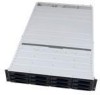
qualified disk drives or SAS cables, contact your Intel sales representative. Appliance Components and Features The main features of the appliance are shown in the following figures. System Front View Figure 1. Intel® Server System SR2612UR Front View 2 Intel® Server System SR2612UR Service Guide - Intel SR2612UR | Service Guide - Page 17
Intel® RAID Controller SRCSASLS4I and Intel® RAID Controller SASWT4I. Please refer to the Intel Customer Support web site under the link for these RAID controllers at:http://www.intel.com/support/motherboards/server/ About the Disk Drives and Drive Carriers The Intel® Server System SR2612UR supports - Intel SR2612UR | Service Guide - Page 18
to the LEDs on the midplane and/or create thermal problems (as well as void the Limited Warranty). Disk drives are hot-swappable. Drive Slot Numbers Figure 4. Intel® Server System SR2612UR Drive Slots and may cause severe damage to the disk drive. 4 Intel® Server System SR2612UR Service Guide - Intel SR2612UR | Service Guide - Page 19
drives. However, the same guidelines apply even if you are filling some of the drive slots with blank drive carriers. Recommended Disk Drive Configurations Figure 5. Intel® Server System SR2612UR Drive Configurations Intel® Server System SR2612UR Service Guide 5 - Intel SR2612UR | Service Guide - Page 20
Unsupported Disk Drive Combinations Figure 6. Unsupported Disk Drive Combinations 6 Intel® Server System SR2612UR Service Guide - Intel SR2612UR | Service Guide - Page 21
www.intel.com/support/motherboards/server/sr2612ur/ Intel® Server System SR2612UR Quick Start User's Guide Provided in the product box Accessories or other Intel server products Spares, Parts List and Configuration Guide Available at: http://www.intel.com/support/motherboards/server/sr2612ur/ or - Intel SR2612UR | Service Guide - Page 22
or Software Latest drivers, firmware updates (BIOS, BMC, and FRUSDR), and utilities To make sure your system falls within the allowed power budget For software to manage your Intel® server Available for download at: http://www.intel.com/support/motherboards/server/sr2612ur/ Click the "Software and - Intel SR2612UR | Service Guide - Page 23
the Intel® Server System SR2612UR. This includes illustrations of the products, a list of the server system features, and diagrams showing the location of important components and connections on the server systems. Figure 7. Intel® Server System SR2612UR Intel® Server System SR2612UR Service Guide - Intel SR2612UR | Service Guide - Page 24
Processor List. Support for 800/1066/1333 MT/s ECC registered (RDIMM) or unbuffered DIMM (UDIMM) DDR3 memory • 12 DIMMs across six memory channels (three channels per processor) • Intel® 5520 chipset I/O Hub • Intel® 82801Jx I/O Controller Hub 10 Intel® Server System SR2612UR Service Guide - Intel SR2612UR | Service Guide - Page 25
II with SW RAID levels 0/1/10 • Optional support for SW RAID 5 with activation key • Slimline bay for slimline SATA optical drive (back) • PCI riser card bracket • Standard control panel provides: - LEDs (front and back) - Power switch (back) Intel® Server System SR2612UR Service Guide 11 - Intel SR2612UR | Service Guide - Page 26
3.1 Server System Components This section helps you identify the components of your server system. If you are near the system, you can also use the Quick Reference Label provided on the inside of the chassis cover to assist in identifying components. 12 Intel® Server System SR2612UR Service Guide - Intel SR2612UR | Service Guide - Page 27
Figure 8. Intel® Server System SR2612UR Configuration Diagram Intel® Server System SR2612UR Service Guide 13 - Intel SR2612UR | Service Guide - Page 28
C. PCI Riser Assembly D. Server Board E. Backplane PCB F. Hard Drive Assembly G. System Air Duct H. Fan Module I. 2.5-inch System Drives J. RAID Card Battery (Optional) K. CD/DVD Drive (Optional) Figure 9. Intel® Server System SR2612UR Components 14 Intel® Server System SR2612UR Service Guide - Intel SR2612UR | Service Guide - Page 29
, blinking amber, amber, off). • The System Identification LED on the front and back panel (see Figure 11 and Figure 12) helps identify the server from among several servers. The ID LED is off by default, and blue when activated by button or software. Intel® Server System SR2612UR Service Guide 15 - Intel SR2612UR | Service Guide - Page 30
1 Fan Fault LED G. CPU 2 Fan Fault LED I. CPU 2 DIMM Fault LEDs B. System Identification LED D. Memory 1 Fan Fault LED F. CPU 1 DIMM Fault LEDs H. Memory 2 Fan Fault LED J. 5V Standby LED Figure 10. Intel® Light-Guided Diagnostic LEDs - Server Board 16 Intel® Server System SR2612UR Service Guide - Intel SR2612UR | Service Guide - Page 31
Figure 11. Intel® Light-Guided Diagnostic LEDs - Standard Control Panel Intel® Server System SR2612UR Service Guide 17 - Intel SR2612UR | Service Guide - Page 32
Degraded Non-critical Critical, non-recoverable Identify active through command No Identification N/A Figure 12. System Power LED Back Panel Server Board Components This section helps you identify the components and connectors on the server board. 18 Intel® Server System SR2612UR Service Guide - Intel SR2612UR | Service Guide - Page 33
AB C D E FG EE DD H I CC J BB AA Z Y X W V U T S R QPO K L NM AF002696 Intel® Server System SR2612UR Service Guide 19 - Intel SR2612UR | Service Guide - Page 34
Processor 2 Socket O. Bridge Board Connector (Intel® Server Chassis) R. 2x4 Power Connector U. System 2 Fan Header X. System 1 Fan Header AA. SGPIO Header DD. I/O Module Mezzanine Connector 1 Figure 13. Server Board Connector and Component Locations 20 Intel® Server System SR2612UR Service Guide - Intel SR2612UR | Service Guide - Page 35
for normal system operation. C. BIOS Default (J1E7) If pins 2-3 are jumpered, the BIOS settings are user passwords are cleared within five to ten seconds after the system is powered on. These pins should be jumpered on 1-2 for normal system operation. Intel® Server System SR2612UR Service Guide - Intel SR2612UR | Service Guide - Page 36
SR2612UR Peripheral Devices The Intel® Server System SR2612UR provides locations and hardware for installing hard drives, CD-ROM drive, or DVD-ROM drive. The drives must be purchased separately. The following figure shows the available options. 22 Intel® Server System SR2612UR Service Guide - Intel SR2612UR | Service Guide - Page 37
Internal fixed 2.5-inch SATA Hard Drive Bays (2) C. Slimline SATA Optical Drive Bay (1) Figure 15. Optional Peripherals Hard Disk Drive Carriers The server system ships with 12 drive carriers for installing 12 SAS or Serial ATA (SATA) hot-swap drives. Intel® Server System SR2612UR Service Guide 23 - Intel SR2612UR | Service Guide - Page 38
supported slimline optical drives, see "Additional Information and Software" on page -7. Intel provides accessory kits for these drives. Control Panel The Intel® Server System SR2612UR only has one control panel option.. Figure 16. Rear Control Panel 24 Intel® Server System SR2612UR Service Guide - Intel SR2612UR | Service Guide - Page 39
Power Switch N/A State Off On Solid On Blink Blink Solid On On Off N/A Description AC Power Off AC power on or DC power on System booted and ready Degraded Non-critical Critical, non-recoverable Identify active through command No Identification N/A Intel® Server System SR2612UR Service Guide 25 - Intel SR2612UR | Service Guide - Page 40
6 and 7 are not used in the Intel® Server System SR2612UR. Active Midplane The following diagram show the location for each connector found on the active midplane. A. SAS Connector B. Backplane Connector Figure 17. Active SAS Midplane Components 26 Intel® Server System SR2612UR Service Guide - Intel SR2612UR | Service Guide - Page 41
Figure 18. 3.5-inch Hot-Swap SAS/SATA Backplane Components (Front View) A. Backplane Power Connector B. Server Board/Midplane GPIO Connector C. Midplane Board Connector Figure 19. 3.5-inch Hot-Swap SAS/SATA Backplane Components (Rear View) Intel® Server System SR2612UR Service Guide 27 - Intel SR2612UR | Service Guide - Page 42
in the second position from the bottom, and so on. For instructions on installing your chassis into a rack, see "Installing Your Intel® Server System SR2612UR into a Rack (Optional)" on page -30. These instructions are also included in the rail kit. 28 Intel® Server System SR2612UR Service Guide - Intel SR2612UR | Service Guide - Page 43
Information" on page v at the beginning of this manual. Note: Whenever you service the system, you must first power down the server and unplug all peripheral devices and the AC power cord Safety Information" on page v at the beginning of this manual.) Intel® Server System SR2612UR Service Guide 29 - Intel SR2612UR | Service Guide - Page 44
of the rail away from each other until the length is correct for your cabinet. Secure the front and rear portions of the rail kit to the front and rear supports as shown in the following figure. Ensure all connections are tightened and secure. 30 Intel® Server System SR2612UR Service Guide - Intel SR2612UR | Service Guide - Page 45
the Rail Kit 4. Tighten the four screws on each rail's slider mechanism. Figure 22. Tightening the Screws on the Rail's Slider Mechanism Caution: A fully loaded appliance is heavy. To avoid personal injury, have someone help you lift the appliance. Intel® Server System SR2612UR Service Guide 31 - Intel SR2612UR | Service Guide - Page 46
. Figure 23. Sliding the Appliance onto the Rails 6. Secure both rackmount ears to the vertical supports using two of the 10-32 x .50- inch screws and carefully snap the plastic rack ear covers in place as shown. The rack installation is complete. 32 Intel® Server System SR2612UR Service Guide - Intel SR2612UR | Service Guide - Page 47
refer to "Drive Installation in the Drive Carrier" on page 75 in this manual. 1. Select an open drive slot. 2. Hold the disk drive so the LEDs are on the left and the lever is fully open. 3. Slide the left side of the drive slot and clicks into place. Intel® Server System SR2612UR Service Guide 33 - Intel SR2612UR | Service Guide - Page 48
. Under no circumstances should the appliance be operated with empty drive slots or with empty drive carrier assemblies as this could cause damage to the LEDs on the backplane and/or create thermal problems. 34 Intel® Server System SR2612UR Service Guide - Intel SR2612UR | Service Guide - Page 49
a Disk Drive Carrier Assembly (or Drive Blank) Note: For disk drive installation instructions, see "Installing the Disk Drives" on page 33. Important Safety Precautions Before you assembly): 1. Press the button on the assembly to release the lever. Intel® Server System SR2612UR Service Guide 35 - Intel SR2612UR | Service Guide - Page 50
a drive blank assembly to maintain correct airflow and cooling. For more information on installing disk drives, see "Installing the Disk Drives" on page 33. 36 Intel® Server System SR2612UR Service Guide - Intel SR2612UR | Service Guide - Page 51
installing the operating system. 6. If you want to install additional drivers or programs (for the PCI cards or other devices), you should also install them at this time. The system is now ready to boot up. Booting the system may take several minutes. Intel® Server System SR2612UR Service Guide 37 - Intel SR2612UR | Service Guide - Page 52
Intel® Server System SR2612UR to a Host Server Connecting to the 1GE iSCSI LAN Data Ports Consult your operating system/software user guide for details on assigning LAN IP addresses to the integrated system 1GE iSCSI data ports. For iSCSI applications running on the Intel® Server System SR2612UR - Intel SR2612UR | Service Guide - Page 53
install one or more 2.5-inch internal drives in the Intel® Server System SR2612UR. For a list of supported drives, contact your Intel sales representative. 1. Ensure the AC power cord(s) are the enclosure. 4. Locate the 2.5-inch drive sled as shown. Intel® Server System SR2612UR Service Guide 39 - Intel SR2612UR | Service Guide - Page 54
captive thumbscrew. 8. The power cables for the 2.5-inch drives are located near the drive sled. Attach the cable(s) to the drive(s). 9. Carefully remove the CPU server board air duct. 40 Intel® Server System SR2612UR Service Guide - Intel SR2612UR | Service Guide - Page 55
cord(s). DVD Installation The Intel® Server System SR2612UR supports an optional DVD. Complete the following steps to install a DVD drive in the Intel® Server System SR2612UR. 1. Ensure the using a Phillips* screwdriver shown in the following figure. Intel® Server System SR2612UR Service Guide 41 - Intel SR2612UR | Service Guide - Page 56
in the following figure and carefully snap the unit in place by aligning the pointed tabs with the screw holes on the DVD unit. 42 Intel® Server System SR2612UR Service Guide - Intel SR2612UR | Service Guide - Page 57
the screw that was removed in Step 7. 10. Using the slimline cable shipped with the system, connect the power end of slimline cable to the power cable located in the enclosure and to remove and install a fan in the Intel® Server System SR2612UR. Intel® Server System SR2612UR Service Guide 43 - Intel SR2612UR | Service Guide - Page 58
holes with the spring clip dimples. Press the fan downward until it snaps into place. 2. Carefully replace the system air duct if it was removed in Step 4. 3. Reinstall the top cover and tighten the captive screw. 4. Reinstall the power cord(s). 44 Intel® Server System SR2612UR Service Guide - Intel SR2612UR | Service Guide - Page 59
cover back and lift it from the enclosure. 4. Locate the midplane (located between the backplane and fans). Figure 38. Midplane 5. Disconnect the I/O cable by depressing the release tab and . 6. Remove the two screws holding the midplane in place. Intel® Server System SR2612UR Service Guide 45 - Intel SR2612UR | Service Guide - Page 60
size of memory is used for both processors. For a list of supported memory vendors and capacities, contact your Intel sales representative. Mixed speed DIMMs are accommodated by using the highest common frequency of all memory modules installed. 46 Intel® Server System SR2612UR Service Guide - Intel SR2612UR | Service Guide - Page 61
Channel Sparing or Channel Mirroring Mode as there are specific memory installation configurations required. 6. To install the DIMM, open the release levers on each side of the memory socket and press down on the DIMM until the release levers snap closed. Intel® Server System SR2612UR Service Guide - Intel SR2612UR | Service Guide - Page 62
(s). PCI Card and Battery Installation The Intel® Server System SR2612UR supports to five PCI-E option cards. A typical configuration uses a PCI-E-based RAID card to communicate with the 12 drive lift the entire PCI cage assembly out of the enclosure. 48 Intel® Server System SR2612UR Service Guide - Intel SR2612UR | Service Guide - Page 63
the type of card installed, there may be cables that have to be routed. In the case of a RAID card, you must route the SAS cable through the fan assembly (where other cables are routed) and connect to the I/O module located just behind the midplane. Intel® Server System SR2612UR Service Guide 49 - Intel SR2612UR | Service Guide - Page 64
DRIVE ASSY I B E J K F A C D G H G - SYSTEM AIR DUCT H - FAN MODULE I - 2.5" SYSTEM DRIVES OPTIONAL HARDWARE J - RAID CARD BATTERY K - CD/DVD DRIVE Figure 44. Mounting an External Battery 13. Reinstall the top cover and tighten the captive screw. 50 Intel® Server System SR2612UR Service Guide - Intel SR2612UR | Service Guide - Page 65
it into the chassis enclosure until it clicks into place. 7. Reinstall the top cover and tighten the captive screw. 8. Reinstall the power cord(s). Replacing the Backplane Board The following sections describe how to replace the backplane board. Intel® Server System SR2612UR Service Guide 51 - Intel SR2612UR | Service Guide - Page 66
Connector from the Backplane 7. Remove the midplane from the enclosure as detailed in the User Guide appendix. (Remove the I/O SAS cable and the two (2) screws holding the midplane in place, then carefully disconnect the midplane from the backplane.) 52 Intel® Server System SR2612UR Service Guide - Intel SR2612UR | Service Guide - Page 67
(7) screws attaching the backplane Figure 49. Removing the Screws that Attach the Backplane 9. Carefully pull back on the top of the backplane and lift it out of the enclosure Figure 50. Pulling Back the Backplane and Lifting It Out of the Enclosure Intel® Server System SR2612UR Service Guide 53 - Intel SR2612UR | Service Guide - Page 68
servicing this unit. At a minimum utilize an ESD grounded wrist strap when handling electrical components. Where possible utilize a grounded ESD mat to place drives and components on. To install the RAID as shown below Figure 51. Locate the battery 54 Intel® Server System SR2612UR Service Guide - Intel SR2612UR | Service Guide - Page 69
sliding the pack in the direction of the arrow on the battery plate until the unit snaps into place. Figure 53. Align the battery pack Intel® Server System SR2612UR Service Guide 55 - Intel SR2612UR | Service Guide - Page 70
Figure 54. Aligning the battery pack 8. Replace and tighten the standoff that was removed in step 6 Figure 55. Replace and tighten standoff 9. Route the cable from the battery pack as shown below. Figure 56. Route the cable 56 Intel® Server System SR2612UR Service Guide - Intel SR2612UR | Service Guide - Page 71
back and lift it from the enclosure. 4. Remove the processor air duct. 5. Remove the PCI riser assembly. 6. Remove the Intel® RMM3, if installed. 7. Disconnect power cables, P1, P2, P3 and Front Panel logic cable, from Motherboard as shown below. Intel® Server System SR2612UR Service Guide 57 - Intel SR2612UR | Service Guide - Page 72
Motherboard as shown below Figure 59. Disconnect the fan cables 9. Remove memory. 10. Remove the processor heatsink(s) and processor(s). 11. Remove the nine screws from the server board and lift the server board from the server system as shown below. 58 Intel® Server System SR2612UR Service Guide - Intel SR2612UR | Service Guide - Page 73
Figure 60. Remove the screws 12. Install the replacement server board. Intel® Server System SR2612UR Service Guide 59 - Intel SR2612UR | Service Guide - Page 74
placed into the proper openings, slowly place the board into the chassis without causing any damage to the bottom side components. Figure 61. Installing the server board 2. Attach the server board with nine screws. Figure 62. Attach the screws 60 Intel® Server System SR2612UR Service Guide - Intel SR2612UR | Service Guide - Page 75
the processor(s). 7. Install processor heatsink(s). 8. If necessary, install the Intel® RMM3. 9. Install the PCI riser assembly. 10. Install the processor air duct. 11. Install the top cover and tighten the captive screw. 12. Install the power cords. Intel® Server System SR2612UR Service Guide 61 - Intel SR2612UR | Service Guide - Page 76
loses voltage, and the server settings stored in CMOS RAM in the RTC (for example, the date and time) may be wrong. Contact your customer service representative or dealer for need to run the BIOS Setup to restore the configuration settings to the RTC. 62 Intel® Server System SR2612UR Service Guide - Intel SR2612UR | Service Guide - Page 77
Installing the Power Distribution Module Removing the Power Distribution Module To remove the server board, follow these steps: 1. Power down the enclosure and remove the cable, from Motherboard as shown below. Figure 65. Disconnect the power cables Intel® Server System SR2612UR Service Guide 63 - Intel SR2612UR | Service Guide - Page 78
power cable "P4" from backplane as shown below. Figure 66. Remove the screws 8. Remove cable chase insert foam from cable chase fan blank and then remove power cable p4 from cable chase fan blank as shown below. Figure 67. Remove cable chase 64 Intel® Server System SR2612UR Service Guide - Intel SR2612UR | Service Guide - Page 79
four screws from the power distribution module and lift the power distribution module from the server system as shown below. Figure 68. Remove the four screws from the PDB 10. Install cable marked "P4" through the cable chase fan blank as shown below. Intel® Server System SR2612UR Service Guide 65 - Intel SR2612UR | Service Guide - Page 80
cable P4 3. Install 2 nylon clamps onto cable "P4", flat side up as shown below. Figure 71. Install the nylon clamps 4. Connect power cable "P4" into backplane and Install 2 screws into nylon clamps and secure to chassis as shown below. 66 Intel® Server System SR2612UR Service Guide - Intel SR2612UR | Service Guide - Page 81
Figure 72. Connecting cable P4 to backplane 5. Insert cable chase insert foam into cable chase fan blank. See picture below for foam orientation. Figure 73. Foam orientation Intel® Server System SR2612UR Service Guide 67 - Intel SR2612UR | Service Guide - Page 82
7. Install the PCI riser assembly. 8. Install the processor air duct. 9. Install the top cover and tighten the captive screw. 10. Install the power cords. 68 Intel® Server System SR2612UR Service Guide - Intel SR2612UR | Service Guide - Page 83
the feature's value field is inaccessible. The following table describes the keyboard commands you can use in the BIOS Setup menus. Table 3. Setup Menu Key Use Key to Press Description Pressing on any menu invokes the general help window. Intel® Server System SR2612UR Service Guide 69 - Intel SR2612UR | Service Guide - Page 84
key is pressed in any major menu, the exit confirmation window is displayed and the user is asked whether changes can be discarded. Setup Defaults - Pressing causes the F9> was pressed without affecting any existing field values. 70 Intel® Server System SR2612UR Service Guide - Intel SR2612UR | Service Guide - Page 85
a web link to necessary software and instructions. Recording the Current BIOS Settings 1. Boot the computer and press when you see the message: Press Key if you want to run SETUP 2. Write down the current settings in the BIOS Setup program. Intel® Server System SR2612UR Service Guide 71 - Intel SR2612UR | Service Guide - Page 86
Erase position (covering pins 2 and 3). 5. Wait ten seconds. 6. Move the Password Clear jumper back to the Password Clear Protect position (covering pins 1 and 2). 7. Close the server system. 8. Power up the server. 72 Intel® Server System SR2612UR Service Guide - Intel SR2612UR | Service Guide - Page 87
The password is now cleared and can be reset by going into the BIOS setup. Intel® Server System SR2612UR Service Guide 73 - Intel SR2612UR | Service Guide - Page 88
3). 5. Wait five seconds. 6. Return the BIOS Default jumper to the normal position (covering pins 1 and 2). 7. Close the server system. 8. Power up the system. The BIOS defaults settings are now restored and can be reset by going into the BIOS setup. 74 Intel® Server System SR2612UR Service Guide - Intel SR2612UR | Service Guide - Page 89
Appendix A: Drive Installation in the Drive Carrier Introduction The Intel® Server System SR2612UR universal drive carrier is either used for mounting drives into an you are installing a replacement drive, remove the original drive from the carrier. Intel® Server System SR2612UR Service Guide 75 - Intel SR2612UR | Service Guide - Page 90
. Use the four holes that position the connector farthest back on the carrier. This will ensure the drive will make good connection with the enclosure midplane. 76 Intel® Server System SR2612UR Service Guide - Intel SR2612UR | Service Guide - Page 91
drives are already dual ported and do not require a mux). This feature is not supported on the storage application array, but is used on other enclosures. Installing a Blank Insert in a Universal at the "rear" of the universal drive carrier. Intel® Server System SR2612UR Service Guide 77 - Intel SR2612UR | Service Guide - Page 92
Figure 77. Orienting the Plastic Insert with the Drive Carrier 2. Carefully install the four (4) 6 x 32 x .25-inch screws supplied with the carrier. Do not overtighten. 78 Intel® Server System SR2612UR Service Guide - Intel SR2612UR | Service Guide - Page 93
on the baseboard System BIOS Version: Intel® Remote Management Module Firmware Version (if applicable): Intel® Management Module BMC Revision (if applicable): BMC/mBMC Version: FRU/SDR Version: HSC Version: Has the latest BIOS been tried? (Yes/No): Intel® Server System SR2612UR Service Guide 79 - Intel SR2612UR | Service Guide - Page 94
/No): Has the latest IMM BMC been tried? (Yes/No): Has the latest RMM Firmware been tried? (Yes/No): Has the latest FRU/SDR been tried? (Yes/No): ducting, Active w/fan, etc Memory: Manufacturer Part Number DRAM Part Number On Intel tested list? 80 Intel® Server System SR2612UR Service Guide - Intel SR2612UR | Service Guide - Page 95
(Example: RedHat* Enterprise Linux, Microsoft* Windows* Server 2003, Service pack 1, OEM CD): Manufacturer: Version: Language version (English, Arabic, Chinese (Simplified)): Service Pack Level or Kernel Revision: Distribution (OEM/Retail Intel® Server System SR2612UR Service Guide 81 - Intel SR2612UR | Service Guide - Page 96
RAID driver been tried? (Yes/No): RAID volumes configuration (disks & RAID level): RAID volume use (Boot device/Data Volume): Is BBU (Battery Backup Unit) installed? (Yes/No): BBU part number Detailed description of issue: Troubleshooting tried: 82 Intel® Server System SR2612UR Service Guide - Intel SR2612UR | Service Guide - Page 97
please provide a brief description below. Have you returned systems or components to your place of purchase because of this issue? If yes, please provide a brief description below. *All other brands and names are property of their respective owners. Intel® Server System SR2612UR Service Guide 83 - Intel SR2612UR | Service Guide - Page 98
84 Intel® Server System SR2612UR Service Guide - Intel SR2612UR | Service Guide - Page 99
identify Blue Description System power OK System fault detected server board fault detected Enclosure ID LED Status Board The LED board is located at the rear of the enclosure above the power supply modules. The following image shows the LED board: Intel® Server System SR2612UR Service Guide 85 - Intel SR2612UR | Service Guide - Page 100
the Disk Drives Each populated disk drive carrier has three LEDs that indicate the status of the disk drive, as described in the following table. Figure 80. Disk Drive LEDs Table 6. LED Status for the Disk Drive LED 1 Condition Not Used Color 86 Intel® Server System SR2612UR Service Guide - Intel SR2612UR | Service Guide - Page 101
LED Status (SAS/SATA) for the Disk Drive LED on constantly with Midplane firmware 105 or Hot Spare Consistency Check software supplied with the RAID controller to manage and monitor the system configuration. LSI MegaRaid is a trademark of LSI Corporation. Intel® Server System SR2612UR Service Guide - Intel SR2612UR | Service Guide - Page 102
88 Intel® Server System SR2612UR Service Guide - Intel SR2612UR | Service Guide - Page 103
/. Note: You will need to log in to the Reseller site to obtain the 24x7 number. Warranty Information To obtain warranty information, visit the following Intel web site: http://support.intel.com/support/motherboards/server/sb/CS-010807.htm Intel® Server System SR2612UR Service Guide 89 - Intel SR2612UR | Service Guide - Page 104
90 Intel® Server System SR2612UR Service Guide - Intel SR2612UR | Service Guide - Page 105
will require additional planning. If NEBS compliance is required for system level products, additional certification planning and design will be required. Product Safety Compliance • CSA 60950-1 Certification (Canada) • UL 60950-1 Listing (USA) Intel® Server System SR2612UR Service Guide 91 - Intel SR2612UR | Service Guide - Page 106
) • GOST R 29216-91 Emissions (Russia) • GOST R 50628-95 Immunity (Russia) • Ukraine Certification (Ukraine) • KCC MIC Notice No. 1997-41 (EMC) & 1997-42 (EMI) (Korea) 92 Intel® Server System SR2612UR Service Guide - Intel SR2612UR | Service Guide - Page 107
Class A Attestation (USA/Canada) • VCCI Certification (Japan) • C-Tick Declaration of Conformity (Australia) • MED Declaration of Conformity (New Zealand) • BSMI Certification (Taiwan) • GOST R Certification / Certification (Russia) Intel® Server System SR2612UR Service Guide 93 - Intel SR2612UR | Service Guide - Page 108
• KCC Certification (Korea) • IRAM Certification (Argentina) • Ecology Declaration (International) • China RoHS Environmental Friendly Use Period • Packaging & Product Recycling Marks 94 Intel® Server System SR2612UR Service Guide - Intel SR2612UR | Service Guide - Page 109
Compliance cETLus Listing Marks Country USA/Canada Marking GS Mark Germany CE Mark Europe IRAM Mark Argentina Ctick Mark Australia / NZ Country of Origin Mark Intel® Server System SR2612UR Service Guide N232 Made in China 95 - Intel SR2612UR | Service Guide - Page 110
(Class A) Japan CANADA ICES-003 CLASS A BSMI Certification Number & Class A Warning Taiwan GOST R Marking Russia KCC Mark (Korean Communications Commission Korea MO04 CPU-SR2612 (A) 96 Intel® Server System SR2612UR Service Guide - Intel SR2612UR | Service Guide - Page 111
California Code of Regulations, Title 22, Division 4.5, and Chapter 33: Best Management Practices for Perchlorate Materials. This product may include a battery which contains Perchlorate material. Intel® Server System SR2612UR Service Guide 97 - Intel SR2612UR | Service Guide - Page 112
reduce the risk of electrical shock, disconnect (2) two power supply cords before servicing. Simplified Chinese: Traditional Chinese: Nordic Ground Marking Connection to Proper Ground Outlet ." "Connect only to a properly earth grounded outlet." 98 Intel® Server System SR2612UR Service Guide - Intel SR2612UR | Service Guide - Page 113
must be anchored to an unmovable support to prevent it from falling over when one or more servers are extended in front of the of problems in your server. Ventilation: The equipment rack must provide sufficient airflow to the front of the server to Intel® Server System SR2612UR Service Guide 99 - Intel SR2612UR | Service Guide - Page 114
connectors that plug into the AC receptacle on the server must be an approved IEC (International Electrotechnical Commission) 320, sheet C13, type female connector. • Cord length and flexibility: Cords must be less than 4.5 meters (14.76 feet) long. 100 Intel® Server System SR2612UR Service Guide - Intel SR2612UR | Service Guide - Page 115
Intel Corporation 5200 N.E. Elam Young Parkway Hillsboro, OR 97124-6497 1-800-628-8686 This equipment has been tested in accordance with the instructions, may cause harmful the equipment off and on, the user is encouraged to try to correct the Intel® Server System SR2612UR Service Guide 101 - Intel SR2612UR | Service Guide - Page 116
Canadian Department of Communications. CE Declaration of Conformity (Europe) This product has been tested in accordance to, and complies with the Low Voltage Directive (73/23/EEC) Install and use the equipment according to the instruction manual. 102 Intel® Server System SR2612UR Service Guide - Intel SR2612UR | Service Guide - Page 117
other components will void the UL listing and other product certifications and approvals. Updated product information for configurations can be found on the Intel Server Builder Web site at the following URL: http://channel.intel.com/go/serverbuilder Intel® Server System SR2612UR Service Guide 103 - Intel SR2612UR | Service Guide - Page 118
Storage Devices: must be UL recognized or UL listed accessory and TUV or VDE Certificationd. Maximum power rating of any one device is 19 watts. Total server configuration is not to exceed the maximum loading conditions of the power supply. 104 Intel® Server System SR2612UR Service Guide - Intel SR2612UR | Service Guide - Page 119
/Assembly Safety Instructions English The power supply in this product contains no user-serviceable parts. Refer servicing only to system-any unpainted metal surface-when handling components. 6. Do not operate the system with the chassis covers removed. Intel® Server System SR2612UR Service Guide - Intel SR2612UR | Service Guide - Page 120
the battery is incorrectly replaced. Replace only with the same or equivalent type recommended by the equipment manufacturer. Dispose of used batteries according to manufacturer's instructions. 106 Intel® Server System SR2612UR Service Guide - Intel SR2612UR | Service Guide - Page 121
ein eigenes Netzkabel. Der Wechselstrom des Systems wird durch den Ein-/Aus-Schalter für Gleichstrom nicht ausgeschaltet. Ziehen Sie jedes Wechselstrom-Netzkabel aus der Steckdose bzw. dem Netzgerät, um den Stromanschluß des Systems zu unterbrechen. Intel® Server System SR2612UR Service Guide 107 - Intel SR2612UR | Service Guide - Page 122
Sie diese gut an. 4. Bringen Sie die Verschlußeinrichtung (Padlock) wieder an und schließen Sie diese, um ein unerlaubtes Öffnen des Systems zu verhindern. 5. Schließen Sie alle externen Kabel und den AC Stromanschlußstecker Ihres Systems wieder an. 108 Intel® Server System SR2612UR Service Guide - Intel SR2612UR | Service Guide - Page 123
. Entsorgen Sie verbrauchte Batterien den Anweisungen des Herstellers entsprechend. Das System wurde für den Betrieb in einer normalen Büroumgebung entwickelt. Der Standort d'alimentation. Veuillez contacter un technicien qualifié en cas de problème. Intel® Server System SR2612UR Service Guide 109 - Intel SR2612UR | Service Guide - Page 124
ère du système, déverrouillez-le et retirez-le. 2. Retirez toutes les vis des panneaux et mettez-les dans un endroit sûr. 3. Retirez les panneaux. 110 Intel® Server System SR2612UR Service Guide - Intel SR2612UR | Service Guide - Page 125
type ou d'un type équivalent recommandé par le fabricant. Disposez des piles usées selon les instructions du fabricant. Le système a été conçu pour fonctionner dans un cadre de travail normal. étant le seul moyen de mettre le système hors tension). Intel® Server System SR2612UR Service Guide 111 - Intel SR2612UR | Service Guide - Page 126
del chasis - o a cualquier tipo de superficie de metal sin pintar. 6. No ponga en marcha el sistema si se han extraído las tapas del chasis. Intel® Server System SR2612UR Service Guide - Intel SR2612UR | Service Guide - Page 127
pilas iguales o del mismo tipo que las recomendadas por el fabricante del equipo. Para deshacerse de las pilas usadas, siga igualmente las instrucciones del fabricante. Intel® Server System SR2612UR Service Guide 113 - Intel SR2612UR | Service Guide - Page 128
correctamente instalada. • "Provisto de espacio suficiente como para acceder a los cables de alimentación, ya que éstos hacen de medio principal de desconexión del sistema. 114 Intel® Server System SR2612UR Service Guide - Intel SR2612UR | Service Guide - Page 129
lucchetto dal retro del sistema qualora ve ne fosse uno installato. 2. Togliere e mettere in un posto sicuro tutte le viti delle coperture. 3. Togliere le coperture. Intel® Server System SR2612UR Service Guide 115 - Intel SR2612UR | Service Guide - Page 130
una presa a muro correttamente installata. • "Dotata di spazio sufficiente ad accedere ai cavi di alimentazione, i quali rappresentano il mezzo principale di scollegamento del sistema. 116 Intel® Server System SR2612UR Service Guide - Intel SR2612UR | Service Guide - Page 131
Enclosure Services (SES) 2.0 based firmware Applications • Microsoft Windows* Storage ServerTM • VMware ESX*, Microsoft Hyper-VTM* and Citrix* XenServerTM virtualization • Open-E* Data Storage Server (DSSTM) • AMI StorTrends* • Unified NAS/iSCSI Intel® Server System SR2612UR Service Guide 117 - Intel SR2612UR | Service Guide - Page 132
support • Redundant cable support 2U Rackmount Enclosure • Dimensions: 3.5 inches H x 17.6 inches W x 31 inches D (8.9 cm H x 44.7 cm W x 78.7 cm D) • Weight with drives: 70 lbs (35 kg) max • Standard Rackmount Rail Kit : 3 Gb SAS; 3 Gb/1.5 Gb SATA 118 Intel® Server System SR2612UR Service Guide - Intel SR2612UR | Service Guide - Page 133
fans" Supported Options • tested to ISO7779 Non-Operating Environment • Temperature: -40° to 70°C • Relative humidity: 5% to 95% (non-condensing) • Altitude: -200 to 40,000 ft. • Shock: 10G at 11ms, 1/2 sine wave pulse • Vibration: 0.5G at 5Hz to 400Hz Intel® Server System SR2612UR Service Guide - Intel SR2612UR | Service Guide - Page 134
registered quality system Environmental Protection • RoHS and WEEE compliant Failure Notifications • SCSI Enclosure Services (SES-2) over I2C physical interface, LEDs, audible alarms, field replaceable unit (FRU) revision and serial number reporting 120 Intel® Server System SR2612UR Service Guide - Intel SR2612UR | Service Guide - Page 135
I/O module(s), as well as error rates and quality of service Qualifications For Newisys qualifications relative to supported options for specific disk drives, software application environments, PCI adapters, and so on, go to www.newisys.com/support. Intel® Server System SR2612UR Service Guide 121 - Intel SR2612UR | Service Guide - Page 136
122 Intel® Server System SR2612UR Service Guide - Intel SR2612UR | Service Guide - Page 137
server should be integrated and serviced only by technically qualified persons. You must adhere to the guidelines in this guide and the assembly instructions in your server manuals in serious injury or death if safety instructions are not followed. Intel® Server System SR2612UR Service Guide 123 - Intel SR2612UR | Service Guide - Page 138
other product categories and environments (such as medical, industrial, residential, alarm systems, and test equipment), other than an ITE application, may require further evaluation. Site and safety requirements when moving and lifting equipment. 124 Intel® Server System SR2612UR Service Guide - Intel SR2612UR | Service Guide - Page 139
. • Do not access the inside of the power supply. There are no serviceable parts in the power supply. Return to manufacturer for servicing. • Power down the chassis and disconnect all power cords before adding or replacing any non hot-plug component. Intel® Server System SR2612UR Service Guide 125 - Intel SR2612UR | Service Guide - Page 140
Airflow Caution: Carefully route cables as directed to minimize airflow blockage and cooling problems. For proper cooling and airflow, operate the chassis only with the chassis covers the covers to the chassis according to the product instructions. 126 Intel® Server System SR2612UR Service Guide - Intel SR2612UR | Service Guide - Page 141
not user serviceable • Return to manufacturer for servicing Deutsch Sicherheitshinweise für den Server Das vorliegende Dokument bezieht sich auf Intel® Serverplatinen, Intel® Servergeh Nichtbeachtung der WARNUNG zu ernsten Verletzungen führen kann. Intel® Server System SR2612UR Service Guide 127 - Intel SR2612UR | Service Guide - Page 142
Industrie, Alarmsysteme oder Prüfgeräte) kann u. U. weitere Tests erfordern. Standortauswahl Das System ist für den Betrieb innerhalb normaler Büroumgebungen geeignet. Wählen die Hauptvorrichtung zum Trennen des Produkts von der Stromversorgung sind. 128 Intel® Server System SR2612UR Service Guide - Intel SR2612UR | Service Guide - Page 143
Transportieren oder Anheben von Geräten. • Entfernen Sie alle Komponenten, die sich leicht abnehmen lassen, um das Gewicht zu reduzieren und die Handhabung zu erleichtern. Intel® Server System SR2612UR Service Guide 129 - Intel SR2612UR | Service Guide - Page 144
den Benutzer wartungsbedürftigen Teile. Schicken Sie das Gerät für Wartungsarbeiten an den Hersteller zurück. • Schalten Sie den Server aus, und ziehen Sie alle Netzkabel ab, bevor Sie Komponenten ein- oder ausbauen, die nicht hot-plug-fähig sind. 130 Intel® Server System SR2612UR Service Guide - Intel SR2612UR | Service Guide - Page 145
dem Server mit der Bauelementseite nach oben auf eine geerdete, statisch entladene Unterlage.Verwenden Sie dazu, sofern verfügbar, eine leitfahige Schaumstoffunterlage, aber niche die Schutzhülle der Platine. Ziehen Sie die Platine nicht über eine Fläche. Intel® Server System SR2612UR Service Guide - Intel SR2612UR | Service Guide - Page 146
Laser- Komponenten. • Laser-Peripheriegeräte oder -Komponenten besitzen keine für den Benutzer wartungsbedürftigen Teile. • Schicken Sie das Gerät für Wartungsarbeiten an den Hersteller zurück. 132 Intel® Server System SR2612UR Service Guide - Intel SR2612UR | Service Guide - Page 147
uniquement par des techniciens qualifiés. Vous devez suivre les informations de ce guide et les instructions d'assemblage des manuels de serveur pour vérifier et maintenir la conformité pales de ventilateur, car cela peut entraîner des blessures. Intel® Server System SR2612UR Service Guide 133 - Intel SR2612UR | Service Guide - Page 148
l'alimentation. Veuillez réutiliser la batterie Domaines d'utilisation prévus Ce produit a été testé comme équipement informatique (ITE) et peut être installé dans des bureaux, des en vue de faciliter la manipulation, retirez tout composant amovible. 134 Intel® Server System SR2612UR Service Guide - Intel SR2612UR | Service Guide - Page 149
ou de supprimer un composant non connectable à chaud. Les alimentations de certains serveurs Intel sont munies de doubles fusibles pôle/neutre: veuillez observer les précautions d'usage en cours de remplacement avant de retirer le bloc du serveur. Intel® Server System SR2612UR Service Guide 135 - Intel SR2612UR | Service Guide - Page 150
panneaux du châssis sont en place. L'utilisation du système sans les panneaux peut endommager les composants système. Pour installer les panneaux : 136 Intel® Server System SR2612UR Service Guide - Intel SR2612UR | Service Guide - Page 151
és. • Fixez les panneaux au châssis en suivant les instructions du produit. Périphériques laser Attention: Pour éviter tout guía y a las instrucciones de montaje de los manuales del servidor para asegurar y mantener el cumplimiento con las embalaje. Intel® Server System SR2612UR Service Guide 137 - Intel SR2612UR | Service Guide - Page 152
la luz solar directa y los radiadores. • Alejada de fuentes de vibración o de golpes físicos. • Aislada de campos electromagnéticos producidos por dispositivos eléctricos. 138 Intel® Server System SR2612UR Service Guide - Intel SR2612UR | Service Guide - Page 153
conexión en funcionamiento. Algunas fuentes de alimentación de electricidad de los servidores de Intel utilizan el polo neutral del fuselaje. Para evitar riesgos de choques eléctricos use fuente de alimentación. Dentro de la fuente de alimentación Intel® Server System SR2612UR Service Guide 139 - Intel SR2612UR | Service Guide - Page 154
el sistema se enfríe antes de abrir las cubiertas. Para que no llegue a tocar los componentes que estén calientes cuando esté realizando una instalación 140 Intel® Server System SR2612UR Service Guide - Intel SR2612UR | Service Guide - Page 155
sueltas dentro del sistema. • Compruebe que los cables, tarjetas adicionales y otros componentes están instalados correctamente. • Sujete las cubiertas a la carcasa siguiendo las instrucciones del producto. Intel® Server System SR2612UR Service Guide 141 - Intel SR2612UR | Service Guide - Page 156
de ningún periférico o dispositivo láser • Los periféricos o dispositivos láser no pueden ser reparados por el usuario • Haga que el fabricante los repare. 142 Intel® Server System SR2612UR Service Guide - Intel SR2612UR | Service Guide - Page 157
简体中文 Intel Intel Intel Web UL Intel® Server System SR2612UR Service Guide 143 - Intel SR2612UR | Service Guide - Page 158
144 Intel® Server System SR2612UR Service Guide - Intel SR2612UR | Service Guide - Page 159
Intel® Server System SR2612UR Service Guide 145 - Intel SR2612UR | Service Guide - Page 160
146 Intel® Server System SR2612UR Service Guide - Intel SR2612UR | Service Guide - Page 161
Intel® Server System SR2612UR Service Guide 147 - Intel SR2612UR | Service Guide - Page 162
148 Intel® Server System SR2612UR Service Guide
-
 1
1 -
 2
2 -
 3
3 -
 4
4 -
 5
5 -
 6
6 -
 7
7 -
8
-
9
-
10
-
11
-
12
-
13
-
14
-
15
-
16
-
17
-
18
-
19
-
20
-
21
-
22
-
23
-
24
-
25
-
26
-
27
-
28
-
29
-
30
-
31
-
32
-
33
-
34
-
35
-
36
-
37
-
38
-
39
-
40
-
41
-
42
-
43
-
44
-
45
-
46
-
47
-
48
-
49
-
50
-
51
-
52
-
53
-
54
-
55
-
56
-
57
-
58
-
59
-
60
-
61
-
62
-
63
-
64
-
65
-
66
-
67
-
68
-
69
-
70
-
71
-
72
-
73
-
74
-
75
-
76
-
77
-
78
-
79
-
80
-
81
-
82
-
83
-
84
-
85
-
86
-
87
-
88
-
89
-
90
-
91
-
92
-
93
-
94
-
95
-
96
-
97
-
98
-
99
-
100
-
101
-
102
-
103
-
104
-
105
-
106
-
107
-
108
-
109
-
110
-
111
-
112
-
113
-
114
-
115
-
116
-
117
-
118
-
119
-
120
-
121
-
122
-
123
-
124
-
125
-
126
-
127
-
128
-
129
-
130
-
131
-
132
-
133
-
134
-
135
-
136
-
137
-
138
-
139
-
140
-
141
-
142
-
143
-
144
-
145
-
146
-
147
-
148
-
149
-
150
-
151
-
152
-
153
-
154
-
155
-
156
-
157
-
158
-
159
-
160
-
161
-
162
 |
 |

Intel
®
Server System SR2612UR Service Guide
i
Intel
®
Server System SR2612UR
Service Guide
A Guide for Technically Qualified Assemblers of Intel
®
Identified Subassemblies/
Products
Intel Order Number E76206-004