Intel SSR212MC2 Hardware Technical Product Specification
Intel SSR212MC2 - Storage Server Hard Drive Array Manual
 |
UPC - 735858199094
View all Intel SSR212MC2 manuals
Add to My Manuals
Save this manual to your list of manuals |
Intel SSR212MC2 manual content summary:
- Intel SSR212MC2 | Hardware Technical Product Specification - Page 1
Intel® Storage Server SSR212MC2 Technical Product Specification Revision 1.2 EPSD Technical Support & Services Group - Intel SSR212MC2 | Hardware Technical Product Specification - Page 2
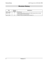
History Intel® Storage Server SSR212MC2 TPS Revision History Date April 24, 2007 May 23, 2007 July 10, 2007 Revision Number 1.0 1.1 1.2 Modifications Release copy. Corrected Battery Backup product code, clarified expansion slots, corrected RAID sku product code nomenclature. Added AC Power - Intel SSR212MC2 | Hardware Technical Product Specification - Page 3
of any features or instructions marked "reserved" or "undefined." Intel reserves these for future definition and shall have no responsibility whatsoever for conflicts or incompatibilities arising from future changes to them. The Intel® Storage Server SSR212MC2 may contain design defects - Intel SSR212MC2 | Hardware Technical Product Specification - Page 4
9 1.5 Enclosure Management Card 10 1.5.1 Summary Of Card Features 10 1.5.2 VSC410 Storage Management Controller 10 1.6 SAS Expander ...11 1.6.1 Embedded Processor 12 1.6.2 Memory Interface & Device Initialization 12 Expander Port Configuration 13 1.7 Chassis Dimensions and Weight - Intel SSR212MC2 | Hardware Technical Product Specification - Page 5
Intel® Storage Server SSR212MC2 TPS Table of Contents 6.1.1 SAS Expander/SAS HBA 28 6.1.1.1 SAS Host Connctor 28 6.1.2 Enclosure Management Card/Backplane 29 6.1.2.1 Power Connectors 29 6.1.2.2 Front Panel Cable 29 6.1.3 Intel® Server Board S5000PSL 30 6.1.3.1 USB Header...30 6.1.4 - Intel SSR212MC2 | Hardware Technical Product Specification - Page 6
List of Figures Intel® Storage Server SSR212MC2 TPS List of Figures Figure 1. Intel® Storage Server SSR212MC2 1 Figure 2. Intel® Storage Server SSR212MC2R Block Diagram 5 Figure 3. Intel® Storage Server SSR212MC2 Block Diagram 6 Figure 4. System Components ...7 Figure 5: Vitesse* VSC410 Block - Intel SSR212MC2 | Hardware Technical Product Specification - Page 7
Table 1: Intel® Storage Server SSR212MC2 Hardware Feature Summary 2 Table 2: Intel® Server Board S5000PSL features 8 Table 3: Intel® RAID Controller SRCSAS144E features 9 Table 4: SATA/SAS Hot Swap backplane features 9 Table 5: SXP Port Configuration 13 Table 6: Chassis Dimensions and Weight - Intel SSR212MC2 | Hardware Technical Product Specification - Page 8
List of Tables Intel® Storage Server SSR212MC2 TPS This page intentionally left blank viii Revision 1.2 - Intel SSR212MC2 | Hardware Technical Product Specification - Page 9
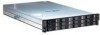
/SAS hard disk drive carriers, dual Intel® PRO/1000 Network connections, and a single 850 W power supply (dual redundant 1+1 capable). Intel®-based system boards and chassis have feature sets designed to support the high-density storage market. Figure 1. Intel® Storage Server SSR212MC2 Revision - Intel SSR212MC2 | Hardware Technical Product Specification - Page 10
Server SSR212MC2 Table 1: Intel® Storage Server SSR212MC2 Hardware Feature Summary Raw Storage Capacity External Drive Bays Hard Disk Drive Supported (external storage) Hard Disk Drive Supported (internal boot) Processor Memory Capacity Memory Type DIMM Slots Enclosure Controller Expandable - Intel SSR212MC2 | Hardware Technical Product Specification - Page 11
fans for cooling the hard drives, baseboard and SAS Host Bus Adapter (HBA) card. Configuration Environment Ambient Temperature Relative Humidity Acoustics Electrostatic Discharge Safety Compliance 850 W continuous, 1+1 redundant power supplies. Intel Storage System SSR212MC2 ships with one 850W - Intel SSR212MC2 | Hardware Technical Product Specification - Page 12
Feature Summary Intel® Storage Server SSR212MC2 1.1 System Components A block diagram of the SSR212MC2R sku (with RAID card) is shown below. Figure 2. Intel® Storage Server SSR212MC2R Block Diagram 4 Revision 1.2 - Intel SSR212MC2 | Hardware Technical Product Specification - Page 13
Intel® Storage Server SSR212MC2 Feature Summary A block diagram of the SSR212MC2 sku (without RAID card) is shown below. 1.5 / 3Gbps (Data) SAS / SATA SAS / SATA SAS / SATA SAS / SATA 4 LANE 4 Lane 4 LANE "Pass Thru" Cable 10 x FAN (5 banks) individually hot plugable 4 LANE 4 Lane PMC 24 port - Intel SSR212MC2 | Hardware Technical Product Specification - Page 14
Feature Summary Intel® Storage Server SSR212MC2 The components included with the storage system are diagrammed below. Figure 4. System Components 6 Revision 1.2 - Intel SSR212MC2 | Hardware Technical Product Specification - Page 15
, as implemented in the Intel Storage System SSR212MC2: Table 2: Intel® Server Board S5000PSL features Feature Processors Memory Chipset Video Connectors/ Headers Expansion Slots: Add-in PCI, PCIX*, PCI Express* Cards LAN Description Socket J (771-pin LGA sockets) supporting one or two Dual-Core - Intel SSR212MC2 | Hardware Technical Product Specification - Page 16
Memory Battery backup SAS connector IOP Card dimensions Serial port Compatible devices Firmware 0, 1, 5, 10, 50 Intel® RAID Controller SRCSAS144E Up to 32 devices per controller NOTE: Up to 12 front accessible carrier mounted hard disk drives are supported in the Intel® Storage Server SSR212MC2 - Intel SSR212MC2 | Hardware Technical Product Specification - Page 17
o Firmware Upgradeability through serial port interface o I2C/IPMI communication with ATX motherboard o I2C/SES communication with SAS Expander Card o I2C communication to local management peripherals • 8 Mbit of Serial Flash Memory for code storage • Drive fault and presence detection • Support for - Intel SSR212MC2 | Hardware Technical Product Specification - Page 18
Feature Summary Intel® Storage Server SSR212MC2 Figure 5: Vitesse* VSC410 Block Diagram A PLL is used to generate the internal core clock of 40.0MHz from an external 4.0MHz clock source or crystal. Additional external component are limited to a single SPI Flash memory device and Two-Wire Serial - Intel SSR212MC2 | Hardware Technical Product Specification - Page 19
Intel® Storage Server SSR212MC2 Feature Summary Figure 6: PMC* PM8388 Block Diagram 1.6.1 Embedded Processor The embedded RISC Processor is a MIPS Technologies* MIPS4K with an EJTAG debugging interface. It supports the SMP protocol and SES and is connected as a virtual port with the device - Intel SSR212MC2 | Hardware Technical Product Specification - Page 20
Intel® Storage Server SSR212MC2 Optionally, the initialization string can point to an external EEPROM. This EEPROM is used to store initialization parameters that are card-specific, like the SAS Base address. Once read, the parameters from the EEPROM will replace those from Flash memory. Expander - Intel SSR212MC2 | Hardware Technical Product Specification - Page 21
Intel® Storage Server SSR212MC2 Feature Summary 1.7 Chassis Dimensions and Weight Table 6: Chassis Dimensions and Weight Height Width (across mounting flange) Width (across body of chassis) Depth (from rack posts to rear of PCI bulkhead) Depth (from rack posts to extremity of chassis) Depth ( - Intel SSR212MC2 | Hardware Technical Product Specification - Page 22
Feature Summary Intel® Storage Server SSR212MC2 1.8 Back Panel I/O Ports and Features The Input/Output (I/O) connectors are integrated to the back panel. The figure below shows the Back Panel I/O ports. Figure 7: Back Panel I/O Ports 14 Revision 1.2 - Intel SSR212MC2 | Hardware Technical Product Specification - Page 23
Intel® Storage Server SSR212MC2 1.9 Front Panel and HDD Bays Feature Summary Figure 8: Chassis Front and Rear Revision 1.2 15 - Intel SSR212MC2 | Hardware Technical Product Specification - Page 24
Feature Summary Intel® Storage Server SSR212MC2 1.9.1 Front/Rear Panel Controls and Indicators The front/rear panel controls and indicators are defined below: On/Off Switch (front mounted) System Reset (front mounted) ID LED Switch (front & rear mounted) NMI (rear mounted) Power Active Unit - Intel SSR212MC2 | Hardware Technical Product Specification - Page 25
Intel® Storage Server SSR212MC2 Feature Summary 1.10 Fan Monitoring The fans provided in the Storage System SSR212MC2 contain a tachometer signal that can be monitored by enclosure management software. 1.10 Rack and Cabinet Mounting Options The chassis was designed to support cabinets that are 19 - Intel SSR212MC2 | Hardware Technical Product Specification - Page 26
Sub-System Intel® Storage Server SSR212MC2 2. Power Sub-System This section provides an overview of the Storage System SSR212MC2 power supply subsystem; the power supply enclosure and the power supply module. NOTE: The Storage System SSR212MC2 ships with one 850 Watt power supply module, mounted - Intel SSR212MC2 | Hardware Technical Product Specification - Page 27
SSR212MC2 power supply assembly is capable of supporting hot swapping of power supply modules in a 1+1 configuration. 2.1.2 Power Supply Outputs The Storage System SSR212MC2 power system supports one or two 850 W Power Supply module's in a 1+1 redundant configuration. The Power Supply Enclosure - Intel SSR212MC2 | Hardware Technical Product Specification - Page 28
Sub-System Intel® Storage Server SSR212MC2 2.1.2.1 Power Supply LED Indicator The power supply module provides a single external bi-color LED to indicate the status of the power supply. When AC is applied to the Power Supply Unit (PSU) and standby voltages are available, the LED will blink green - Intel SSR212MC2 | Hardware Technical Product Specification - Page 29
Intel® Storage Server SSR212MC2 System Cooling Module 3. System Cooling Module The Storage System SSR212MC2 includes ten individual fans that collectively make up the cooling module. Each fan can be removed (Hot Swapped) individually for ease of maintenance. The Power Supply Module contains two - Intel SSR212MC2 | Hardware Technical Product Specification - Page 30
Chassis Bays Intel® Storage Server SSR212MC2 4. Chassis Bays The Storage System SSR212MC2 chassis provides twelve hard drive bays at the front of the chassis. All hard drive bays may be populated with a carrier-mounted 3.5 inch SATA or SAS hard disk drive. Figure 13: Drive Carrier Removal 22 - Intel SSR212MC2 | Hardware Technical Product Specification - Page 31
Intel® Storage Server SSR212MC2 Chassis Bays 4.1 Hard Disk Drive Bays The Storage System SSR212MC2 chassis can support up to twelve carrier-mounted SATA or SAS, 3.5 inch x 1 inch, hard disk drives. The drives may be "electrically" hot-swapped while the system power is applied, but caution should - Intel SSR212MC2 | Hardware Technical Product Specification - Page 32
Chassis Bays Intel® Storage Server SSR212MC2 Figure 14: Hard Disk Drive Bays 4.1.1 Hard Disk Drive Carrier Each hard drive used in the system must be mounted to a drive carrier, making insertion and extraction of the drive from the chassis very simple. Each drive tray has its own dual purpose - Intel SSR212MC2 | Hardware Technical Product Specification - Page 33
Intel® Storage Server SSR212MC2 Chassis Bays Figure 15: Hard Drive Carrier Assembly Revision 1.2 25 - Intel SSR212MC2 | Hardware Technical Product Specification - Page 34
Boot Drives (optional) Intel® Storage Server SSR212MC2 5. Internal Boot Drives (optional) Included inside the Intel® Storage Server SSR212MC2 is a dual boot drive enclosure, that includes the cabling to accommodate either one or two optional SAS or SATA drives. 5.1 SAS One or two 2.5" SAS drives - Intel SSR212MC2 | Hardware Technical Product Specification - Page 35
Intel® Storage Server SSR212MC2 6. System Interconnection System Interconnection 6.1 Internal Chassis Cables The following cables are provided: 6.1.1 6.1.1.1 SAS Expander/SAS HBA SAS Host Connctor: FCI 10045646-002 Header, SAS 4i, 1×32 way, vertical, SMD. Table 15: SAS 4i Host Connector Pin - Intel SSR212MC2 | Hardware Technical Product Specification - Page 36
System Interconnection Intel® Storage Server SSR212MC2 6.1.2 6.1.2.1 Enclosure Management Card/Backplane Power Connectors: 2 × Samtec IPS1-105-01-S-D-RA, Socket, 2×5 way, right angle , PIH Table 16: EM Card PWR_A Connector Pin Signal Name 1 +12V5 3 GND 5 GND 7 GND 9 +5V Pin Signal Name - Intel SSR212MC2 | Hardware Technical Product Specification - Page 37
sensor positive side remote sensor negative side Ground USB +5V Power Ground USB differential Data + USB differential Data - Ground +5V Stand-By Power 6.1.3 6.1.3.1 Intel® Server Board S5000PSL One USB Header locted under the Boot Drive Enclosure. If this header is to be used for an internal - Intel SSR212MC2 | Hardware Technical Product Specification - Page 38
System Interconnection Intel® Storage Server SSR212MC2 6.2 External Rear I/O Panel Connectors The Storage System SSR212MC2 provides an aperture for the rear I/O ports. The following I/O ports available: • Two RJ-45 LAN connectors • One DB-9 Serial Port • One Stacked PS2 port for - Intel SSR212MC2 | Hardware Technical Product Specification - Page 39
Intel® Storage Server SSR212MC2 Regulatory Information 7. Regulatory Information 6.1 Product Regulation Requirements Intended with Class A emission requirements as it is intended for a commercial type market place. Intel targets 10db margin to Class A Limits FCC /ICES-003 - Emissions (USA/Canada) - Intel SSR212MC2 | Hardware Technical Product Specification - Page 40
Regulatory Information Intel® Storage Server SSR212MC2 7.1.3 Certifications / Registrations / Declarations UL Certification (US/Canada) CE Declaration of Conformity (CENELEC Europe) FCC/ICES-003 Class A Attestation (USA/Canada) VCCI Certification (Japan) C-Tick Declaration - Intel SSR212MC2 | Hardware Technical Product Specification - Page 41
Intel® Storage Server SSR212MC2 Regulatory Information The product must be marked with the correct regulatory markings to support shall contain < 100 ppm of cadmium. 7.2 Restriction of Hazardous Substances (RoHS) Intel has a system in place to restrict the use of banned substances in accordance - Intel SSR212MC2 | Hardware Technical Product Specification - Page 42
Environmental Limits Intel® Storage Server SSR212MC2 8. Environmental Limits 8.1 System Office Environment Table 24 inch free fall, although cosmetic damage may be present (chassis weight 30 lbs) ±15 Kilovolt (KV) per Intel® Environmental test specification 3600 BTU/hour (at 850W) 8.2 System - Intel SSR212MC2 | Hardware Technical Product Specification - Page 43
Intel® Storage Server SSR212MC2 Environmental Limits 8.3 Environmental Limits The following table summarizes environmental limits, both operating and non-operating. Table 21: Operating and Non-Operating Environmental Limits Temperature Non- - Intel SSR212MC2 | Hardware Technical Product Specification - Page 44
MTBF Intel® Storage Server SSR212MC2 9. Calculated MTBF The Mean Time Between Failures (MTBF) for the Storage System SSR212MC2 is calculated at 30,800 hours operating at 35 degrees C. The following table shows the MTBF numbers for individual components within the chassis, and does not include hard - Intel SSR212MC2 | Hardware Technical Product Specification - Page 45
Intel® Storage Server SSR212MC2 Word / Acronym A AC ACA ACPI ANSI ATA BA BMC BTU C CF CMOS CPD D2D dBA DDR DIMM DMA DOM ECC EEB EEPROM EMC EMP ESD - Intel SSR212MC2 | Hardware Technical Product Specification - Page 46
I/O iSCSI ITE K KB KV KHz LAN LED LPC MB Mb/s MCH MHz mm msec MTBF MTTR NIC OTP OVP PCI PDB PFC PIO PLD PSON PSU PWT RAID RH RI SAN SAS SCA SCC SDR SDRAM SE SMBIOS II Intel® Storage Server SSR212MC2 Integrated Circuit I/O Controller Hub Internet Database Connector Integrated Drive Electronics Intel - Intel SSR212MC2 | Hardware Technical Product Specification - Page 47
Intel® Storage Server SSR212MC2 SOIC SRAM SSI TQFP TB UART µF µS USB V VA VCCI VQFP VRM W Small Outline Integrated Circuit Static Random Access Memory Server System Infrastructure Thin Quad Flat Pack Terabyte Universal Asynchronous Receiver Transmitter Micro Farad (1 x 10⁻⁶ Farads) Micro Second (1
-
 1
1 -
 2
2 -
 3
3 -
 4
4 -
 5
5 -
 6
6 -
 7
7 -
8
-
9
-
10
-
11
-
12
-
13
-
14
-
15
-
16
-
17
-
18
-
19
-
20
-
21
-
22
-
23
-
24
-
25
-
26
-
27
-
28
-
29
-
30
-
31
-
32
-
33
-
34
-
35
-
36
-
37
-
38
-
39
-
40
-
41
-
42
-
43
-
44
-
45
-
46
-
47
 |
 |

Intel® Storage Server
SSR212MC2
Technical Product Specification
Revision 1.2
EPSD Technical Support & Services Group