Intel TIGI2U User Guide
Intel TIGI2U - Carrier Grade Server Manual
 |
UPC - 735858176958
View all Intel TIGI2U manuals
Add to My Manuals
Save this manual to your list of manuals |
Intel TIGI2U manual content summary:
- Intel TIGI2U | User Guide - Page 1
Intel® Carrier Grade Server TIGI2U User Guide A Guide for Technically Qualified Assemblers of Intel® Identified Subassemblies/Products Order Number: D15006-004 - Intel TIGI2U | User Guide - Page 2
are trademarks or registered trademarks of Intel Corporation or its subsidiaries in the United States and other countries. * Other names and brands may be claimed as the property of others. Copyright © 2007, Intel Corporation. All Rights Reserved. ii Intel® Carrier Grade Server TIGI2U User Guide - Intel TIGI2U | User Guide - Page 3
4 provides troubleshooting information. In this chapter, you will find BIOS error messages and POST (Power-on Self Test) code messages. You will also find suggestions for performing troubleshooting activities to identify the source of a problem. Intel® Carrier Grade Server TIGI2U User Guide iii - Intel TIGI2U | User Guide - Page 4
about the accessories, memory, processors, and third-party hardware that has been tested and can be used with your board, and for ordering information for Intel products, see http://support.intel.com/support/motherboards/server/TIGI2U/compat.htm. iv Intel® Carrier Grade Server TIGI2U User Guide - Intel TIGI2U | User Guide - Page 5
order to connect these interfaces metalically to OSP wiring. All LAN ports must be installed with shielded cabling which must be grounded at both ends. Intel® Carrier Grade Server TIGI2U User Guide v - Intel TIGI2U | User Guide - Page 6
. If the server power cord is plugged into a wall AC outlet, the safety ground conductor in the power cord provides proper grounding only for the server. You must provide additional, proper grounding for the rack and other devices installed in it. vi Intel® Carrier Grade Server TIGI2U User Guide - Intel TIGI2U | User Guide - Page 7
A maximum per feed pair. If the DC power system for the equipment rack is installed with more than 10 amperes of protection, you must provide supplemental protection for the server. The overall current rating of a server configured is 10 amperes. Intel® Carrier Grade Server TIGI2U User Guide vii - Intel TIGI2U | User Guide - Page 8
to modify or use an AC power cordset that is not the exact type required. You must use a power cordset that meets the server. The rack selected and the ventilation provided must be suitable to the environment in which the server will be used. viii Intel® Carrier Grade Server TIGI2U User Guide - Intel TIGI2U | User Guide - Page 9
seguridad y precaución de este documento antes de realizar cualquiera de las instrucciones. Vea Intel Server Boards and Server Chassis Safety Information en el CD Resource y/o en http://support.intel.com/support/motherboards/server/sb/CS-010770.htm. Intel® Carrier Grade Server TIGI2U User Guide ix - Intel TIGI2U | User Guide - Page 10
Board 26 Power Supply ...27 System Cooling ...28 Hardware Requirements ...28 Processor ...28 Memory ...29 Platform Installations and Upgrades 33 Before You Begin ...33 Tools and Supplies Needed Drive 49 Installing the CD-ROM / DVD-ROM Drive 50 10 Intel® Carrier Grade Server TIGI2U User Guide - Intel TIGI2U | User Guide - Page 11
Replacing the Power Supply 55 Removing the Power Supply 55 Installing the Power Supply 56 DC Power In Male Connector Configuration 56 Grounding a DC Powered System 57 Specific Problems and Corrective Actions 90 Power Light Does Not Light 90 Intel® Carrier Grade Server TIGI2U User Guide 11 - Intel TIGI2U | User Guide - Page 12
for Intel Chassis Subassembly Products 111 Extent of Limited Warranty 111 Warranty Limitations and Exclusions 112 Limitations of Liability 112 How to Obtain Warranty Service 113 Telephone Support 113 Returning a Defective Product 114 12 Intel® Carrier Grade Server TIGI2U User Guide - Intel TIGI2U | User Guide - Page 13
Removing the Power Supply 55 Figure 33. Installing the Power Supply 56 Figure 34. DC Power In Male Power Interface Board 69 Figure 48. Installing the Power Interface Board 70 Figure 49. Removing the Serial/Alarms Cable Threaded Standoffs 71 Intel® Carrier Grade Server TIGI2U User Guide - Intel TIGI2U | User Guide - Page 14
. Removing the Server Board 74 Figure 54. Installing the Server Board 75 Figure 55. Securing SCSI Cable to Server Board Connector 76 Figure 56. Replacing the Battery 78 Figure 57. Password Recovery Jumper 85 Figure 58. CMOS Recovery Jumper 86 14 Intel® Carrier Grade Server TIGI2U User Guide - Intel TIGI2U | User Guide - Page 15
Configuration Jumper [J1H2 24 LED Activity Definitions 25 Keyboard Commands 83 BIOS Error Messages 97 POST Error Beep Codes 98 Error Beep Codes Provided by Intel® Management Modules 98 Product Certification Markings 101 Intel® Carrier Grade Server TIGI2U User Guide 15 - Intel TIGI2U | User Guide - Page 16
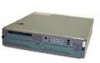
a list of the server features, and diagrams showing the location of important components and connections on the server platform. The Intel® Carrier Grade Server TIGI2U is shown in the following diagram. Figure 1. Intel® Carrier Grade Server TIGI2U 16 Intel® Carrier Grade Server TIGI2U User Guide - Intel TIGI2U | User Guide - Page 17
Slot technology. Capable of supporting riser cards that follows PCI-X specifications. The riser card can support up to three full-height, full-length PCI-X 64/100 MHz add-in cards. On-board ATI* RAGE XL video controller with 8MB SDRAM Continued Intel® Carrier Grade Server TIGI2U User Guide 17 - Intel TIGI2U | User Guide - Page 18
Intel® Management Module - Advanced Edition or Professional Edition Support for Intel® Server Management 8.x Intel® Light-Guided Diagnostics on all field replaceable units (FRUs) Intel® Server Management 5.8 support Telco Alarm Manager (TAM) 18 Intel® Carrier Grade Server TIGI2U User Guide - Intel TIGI2U | User Guide - Page 19
B. Processor Air Duct F. System Fans G. Front Panel I/O Board C. Power Supplies D. PCI Riser Card Assembly E. Intel® Server Board SE7520JR2 H. SCSI Hard Disk Drive Carriers I. Peripheral Bay (CD-ROM or DVD-ROM drive) Figure 2. System Components Intel® Carrier Grade Server TIGI2U User Guide 19 - Intel TIGI2U | User Guide - Page 20
J Video Connector D Optional second power supply or filler panel (filler panel shown) K USB 1 E Power Supply L USB 0 F PS/2 Mouse and Keyboard Connectors M Server Management Port G Rear Serial Port ) 100 Mbps connection 1000 Mbps connection 20 Intel® Carrier Grade Server TIGI2U User Guide - Intel TIGI2U | User Guide - Page 21
relay will be engaged. When continuously lit, indicates the presence of a Power System Fault. The front panel power alarm relay will be engaged. Continuously lit when activated either by a software command or by the front panel ID button. continued Intel® Carrier Grade Server TIGI2U User Guide 21 - Intel TIGI2U | User Guide - Page 22
either NIC. K Main power LED (green) When continuously lit, indicates the presence of DC power in the server. The LED goes out when the power is turned off or if the power source is disrupted. L 5. Optional Peripheral CD-ROM or DVD-ROM Drive 22 Intel® Carrier Grade Server TIGI2U User Guide - Intel TIGI2U | User Guide - Page 23
O. USB header (1 x 10) G. Processor socket 1 P. IDE power connector H. Processor socket 2 Q. SCSI channel A I. +12V processor power R. 120-pin connector for Intel® Management Module Figure 6. Intel® Server Platform TIGI2U Board Diagram Intel® Carrier Grade Server TIGI2U User Guide 23 - Intel TIGI2U | User Guide - Page 24
normal system operation. (line "A" in figure 2-3 If these pins are jumpered, administrator and user passwords will be cleared on the above) next reset. These pins should not be jumpered for These pins should not be jumpered for normal operation. 24 Intel® Carrier Grade Server TIGI2U User Guide - Intel TIGI2U | User Guide - Page 25
to the power supply, server baseboard, drive carrier assemblies, and hot plug disk drives 1 and 2 FPIO SCSI Subsystem Status LEDs The status LEDs give the user a visual indication LED Activity Definitions Drive Active Fault Condition X X X Intel® Carrier Grade Server TIGI2U User Guide 25 - Intel TIGI2U | User Guide - Page 26
the CD-ROM drive and the FPIO system board. The interface board has standard IDE and power connectors for interfacing to the CD-ROM drive, and has a high-density blind-mate connector for interfacing to the FPIO system board. Figure 8. SysCon Board 26 Intel® Carrier Grade Server TIGI2U User Guide - Intel TIGI2U | User Guide - Page 27
Server Platform Features Power Supply The power supply cage supports up to two hot-swap power supplies (either AC input or DC input) in a (1+1) redundant configuration. A power supply filler module for the empty power supply site is supplied 200VAC Intel® Carrier Grade Server TIGI2U User Guide 27 - Intel TIGI2U | User Guide - Page 28
meet the requirements outlined below. For a list of qualified components, see the links under "Additional Information and Software." Processor The server board accommodates two Intel® Xeon™ 3.2 GHz processors operating at 800 MHz FSB with 2MB cache. 28 Intel® Carrier Grade Server TIGI2U User Guide - Intel TIGI2U | User Guide - Page 29
or memory mirroring must be considered. Memory Sparing and Mirroring The Intel® E7520 chipset includes hardware that supports memory mirroring and memory on-line sparing. Both memory mirroring and memory of the data become corrupt at the same time. Intel® Carrier Grade Server TIGI2U User Guide 29 - Intel TIGI2U | User Guide - Page 30
the primary DIMM is removed from service and the spare DIMM takes Intel® Carrier Grade Server TIGI2U must comply with the DDR specifications. For a complete list of supported memory DIMMs, see the links under "Additional Information and Software." 30 Intel® Carrier Grade Server TIGI2U User Guide - Intel TIGI2U | User Guide - Page 31
performance and reliability may be impacted or the DIMMs may not function under the determined frequency. For ECC functionality, all installed DIMMs must be ECC. Intel® Carrier Grade Server TIGI2U User Guide 31 - Intel TIGI2U | User Guide - Page 32
- Intel TIGI2U | User Guide - Page 33
Before working with your server product, pay close attention to the safety instructions at the beginning of this manual. See "Safety Information." Tools and Supplies Needed Phillips* when following the installation steps in this chapter. Intel® Carrier Grade Server TIGI2U User Guide 33 - Intel TIGI2U | User Guide - Page 34
Platform Installations and Upgrades Figure 9. System Cable Routing 34 Intel® Carrier Grade Server TIGI2U User Guide - Intel TIGI2U | User Guide - Page 35
AC power cable or disconnect the DC mains. None of the components inside the platform are hot-swappable. To mitigate damage to equipment from static electricity discharge an antistatic wriststrap connected to earth ground must be worn be service Intel® Carrier Grade Server TIGI2U User Guide 35 - Intel TIGI2U | User Guide - Page 36
the CD-ROM / DVD-ROM drive area and slide the cover forward until it clicks into place (see letter "A"). 3. Reconnect all peripheral devices and the AC power cord or the DC mains. Figure 11. Installing the Chassis Cover 36 Intel® Carrier Grade Server TIGI2U User Guide - Intel TIGI2U | User Guide - Page 37
screws are loosened, the bezel will drop from the chassis. 2. Remove the front bezel from the chassis (see letter "B"). Figure 12. Removing the Front Bezel Intel® Carrier Grade Server TIGI2U User Guide 37 - Intel TIGI2U | User Guide - Page 38
Platform Installations and Upgrades Installing the Front Bezel 1. While holding the front bezel in place (see letter "A"), tighten the captive screws at the left and right edges of the bezel (see letter "B"). Figure 13. Installing the Front Bezel 38 Intel® Carrier Grade Server TIGI2U User Guide - Intel TIGI2U | User Guide - Page 39
the chassis cover. For instructions, see "Removing the Chassis Cover." 3. Remove the screws at the top of the air duct (see letter "A"). 4. Lift the air duct from the server platform (see letter "B"). Figure 14. Removing the Processor Air Duct Intel® Carrier Grade Server TIGI2U User Guide 39 - Intel TIGI2U | User Guide - Page 40
be flush with the top surface of PCI adapter assembly. 3. Replace the chassis cover if you have completed all work inside of the chassis. For instructions, see "Installing the Chassis Cover." Figure 15. Installing the Processor Air Duct 40 Intel® Carrier Grade Server TIGI2U User Guide - Intel TIGI2U | User Guide - Page 41
follow these steps: 1. Power down the server system and unplug all peripheral devices and the AC power cable or the DC mains. 2. Remove the chassis cover. For instructions, see "Removing the Chassis place. Make sure the clips are firmly in place. Intel® Carrier Grade Server TIGI2U User Guide 41 - Intel TIGI2U | User Guide - Page 42
or server board. Keep part of your body in contact with the metal chassis to dissipate the static charge while handling the processor. (2) Avoid moving around unnecessarily. Follow the instructions below to remove and then install a processor. 42 Intel® Carrier Grade Server TIGI2U User Guide - Intel TIGI2U | User Guide - Page 43
the Processor 1. Power down the server system and unplug all peripheral devices and the AC power cable or the DC mains. 2. Remove the chassis cover. For instructions, see "Removing the processor. 7. Lift the processor lever. 8. Remove the processor. Intel® Carrier Grade Server TIGI2U User Guide 43 - Intel TIGI2U | User Guide - Page 44
follow these instructions: 1. Power down the server system and unplug all peripheral devices and the AC power cable or the DC mains. 2. Remove the chassis cover. For instructions, see 19. Figure 19. Installing the Processor in the Processor Socket 44 Intel® Carrier Grade Server TIGI2U User Guide - Intel TIGI2U | User Guide - Page 45
firmly tightened. Figure 21. Installing Heat Sink 10. Install the processor air duct. The air duct must be in place for proper system cooling. For instructions, see "Installing the Processor Air Duct." Intel® Carrier Grade Server TIGI2U User Guide 45 - Intel TIGI2U | User Guide - Page 46
. 5. Set any jumpers and/or switches on the drive according to the drive manufacturer's instructions. 6. With the drive circuit-side down, position the connector end of the drive so that it is facing the rear of the drive carrier (see letter "A"). 46 Intel® Carrier Grade Server TIGI2U User Guide - Intel TIGI2U | User Guide - Page 47
by itself. 9. When the black drive carrier lever begins to close by itself, push on it to lock the drive assembly into place (see letter "B"). Intel® Carrier Grade Server TIGI2U User Guide 47 - Intel TIGI2U | User Guide - Page 48
drive, you must first take the server out of service, turn off all peripheral devices connected to the system, turn off the system by pressing the power button, and unplug the AC power cord from the system or wall outlet or disconnect the DC mains. 48 Intel® Carrier Grade Server TIGI2U User Guide - Intel TIGI2U | User Guide - Page 49
/ DVD-ROM Drive 1. Power down the server system and unplug all peripheral devices and the AC power cable or the DC mains. 2. Remove the chassis cover. For instructions, see "Removing the Chassis . Removing CD-ROM / DVD-ROM Drive Assembly from Chassis Intel® Carrier Grade Server TIGI2U User Guide 49 - Intel TIGI2U | User Guide - Page 50
assembly into the chassis (see letter "B"). 5. Attach the drive power and data cables at the rear of the drive. When the instructions, see "Removing the Chassis Cover." 7. Install the front bezel. For instructions, see "Installing the Front Bezel." 50 Intel® Carrier Grade Server TIGI2U User Guide - Intel TIGI2U | User Guide - Page 51
For instructions, see "Removing the Chassis Cover." 3. Disconnect the power cable to the riser card assembly. 4. Lift blue tabs and pull up on the riser to remove the riser card assembly from the chassis. Figure 27. Removing Riser Assembly from Chassis Intel® Carrier Grade Server TIGI2U User Guide - Intel TIGI2U | User Guide - Page 52
When populating add-in cards, the add-in cards must be installed starting with the slot furthest from the server board. For example, when using a three slot riser, a single add-in card must be installed in Installing Low-Profile PCI Card into Riser 52 Intel® Carrier Grade Server TIGI2U User Guide - Intel TIGI2U | User Guide - Page 53
the chassis cover. For instructions, see "Installing the Chassis Cover." Removing a PCI Add-in Card 1. Power down the server system and unplug all peripheral devices and the AC power cable or the DC PCI card from the riser card slot (see letter "C"). Intel® Carrier Grade Server TIGI2U User Guide 53 - Intel TIGI2U | User Guide - Page 54
a Low-Profile PCI Card Figure 31. Removing a Full Height PCI Card 6. Insert the empty PCI riser assembly into the chassis. 7. Install the chassis cover. For instructions, see "Installing the Chassis Cover." 54 Intel® Carrier Grade Server TIGI2U User Guide - Intel TIGI2U | User Guide - Page 55
and the AC power cable or the DC mains. 2. Depress and hold the green lever to disengage the power supply (see letter "A"). 3. Grasp the black handle and pull the power supply from the chassis (see letter "B"). Figure 32. Removing the Power Supply Intel® Carrier Grade Server TIGI2U User Guide 55 - Intel TIGI2U | User Guide - Page 56
letter "B" in Figure 34). 3. Insert each wire all the way and tighten to 24 in-lb (2.7 N-m) torque (see letter "C" in Figure 34). Figure 34. DC Power In Male Connector Configuration 56 Intel® Carrier Grade Server TIGI2U User Guide - Intel TIGI2U | User Guide - Page 57
fans, you must first take the server out of service, turn off all peripheral devices connected to the system, turn off the system by pressing the power button, and unplug the AC power cord from the system or wall outlet or disconnect the DC mains. Intel® Carrier Grade Server TIGI2U User Guide 57 - Intel TIGI2U | User Guide - Page 58
Four-Fan Assembly 1. Power down the server system and unplug all peripheral devices and the AC power cable or the DC mains. 2. Remove the chassis cover. For instructions, see "Removing the "C" in Figure 36). Figure 36. Removing the Four-Fan Assembly 58 Intel® Carrier Grade Server TIGI2U User Guide - Intel TIGI2U | User Guide - Page 59
connectors on the front panel I/O board (see letter "C"). The fan connectors are labeled on the front panel I/O board. Figure 37. Installing the Four-Fan Assembly Intel® Carrier Grade Server TIGI2U User Guide 59 - Intel TIGI2U | User Guide - Page 60
the following instructions. It is not necessary to power down the server to replace the mini-bezel. 1. Remove the front bezel. For instructions, see " front bezel. For instructions, see "Installing the Front Bezel." Figure 38. Removing the Mini Bezel 60 Intel® Carrier Grade Server TIGI2U User Guide - Intel TIGI2U | User Guide - Page 61
duct. For instructions, see "Removing the Processor Air Duct". 5. Remove the power interface board. For instructions, see "Removing the Power Interface Board." 6. Remove the four-fan assembly. For instructions, see "Removing the Four-Fan Assembly." Intel® Carrier Grade Server TIGI2U User Guide 61 - Intel TIGI2U | User Guide - Page 62
7. Disconnect the following cables on the Front Panel I/O Board: Power interface board power from J1A1 CD-ROM / DVD-ROM data and power cables from the rear of the CD-ROM or DVD-ROM drive in Figure 39). Figure 39. Removing the Front Panel Board 62 Intel® Carrier Grade Server TIGI2U User Guide - Intel TIGI2U | User Guide - Page 63
board. To replace the light pipe using an existing front panel I/O board, use the instructions under the following headings, replacing the existing front panel I/O board instead of installing a into place. Figure 40. Replacing the Light Pipe Intel® Carrier Grade Server TIGI2U User Guide 63 - Intel TIGI2U | User Guide - Page 64
the Power Interface Board." 7. Install the power supply. For instructions, see "Installing the Power Supply." 8. Reconnect all cables to the Front Panel I/O Board. Note that most connectors are labeled to match the connection point on the boards. 64 Intel® Carrier Grade Server TIGI2U User Guide - Intel TIGI2U | User Guide - Page 65
Figure 42. Cabling to Front Panel Board A. Power B. SCSI Channel B Cable C. USB D. Front Panel Connector E. IDE Cable F. Fan Connector Cable G. Telco Alarms Cable 9. Install the chassis cover. For instructions, see "Installing the Chassis Cover." Intel® Carrier Grade Server TIGI2U User Guide 65 - Intel TIGI2U | User Guide - Page 66
below) and remove the riser board (see letter "C" in the figures below). 7. If replacing the full-height riser board, unplug the 5V power cable from the riser board (see letter "D" in Figure 44). Figure 43. Removing the Low-Profile PCI Riser Board 66 Intel® Carrier Grade Server TIGI2U User Guide - Intel TIGI2U | User Guide - Page 67
Full Height PCI Riser Board 8. If replacing the full-height riser board, first plug the 5V power cable into the riser board (see letter "A" in Figure 46). 9. Depress and hold the blue Figure 46). Figure 45. Installing the Low-Profile PCI Riser Board Intel® Carrier Grade Server TIGI2U User Guide 67 - Intel TIGI2U | User Guide - Page 68
boards, you must first take the server out of service, turn off all peripheral devices connected to the system, turn off the system by pressing the power button, and unplug the AC power cord from the system or wall outlet or disconnect the DC mains. 68 Intel® Carrier Grade Server TIGI2U User Guide - Intel TIGI2U | User Guide - Page 69
interface retention lever (see letter "A") and pull up to release the power interface board from the placement pegs (see letter "B"). 9. Lift the power interface board from the chassis (see letter "C"). Figure 47. Removing the Power Interface Board Intel® Carrier Grade Server TIGI2U User Guide 69 - Intel TIGI2U | User Guide - Page 70
the chassis cover. For instructions, see "Installing the Chassis Cover." Replacing the Serial/Alarms Cable The Intel® Carrier Grade Server TIGI2U includes a serial/alarms cable. To replace the serial/alarms cable, use the following instructions. 70 Intel® Carrier Grade Server TIGI2U User Guide - Intel TIGI2U | User Guide - Page 71
/Alarms Cable 1. Power down the server system and unplug all peripheral devices and the AC power cable or the DC mains. 2. Remove the chassis cover. For instructions, see "Removing Figure 50. Removing the Serial/Alarms Connector from the Chassis Intel® Carrier Grade Server TIGI2U User Guide 71 - Intel TIGI2U | User Guide - Page 72
the Serial/Alarms Connector into Chassis 2. Install the threaded standoffs as shown in Figure 52. Figure 52. Installing the Serial/Alarms Cable Threaded Standoffs 72 Intel® Carrier Grade Server TIGI2U User Guide - Intel TIGI2U | User Guide - Page 73
board, use the following instructions. CAUTION Before replacing any of the server boards, you must first take the server out of service, turn off all peripheral devices connected to the system, turn off the system by pressing the power button, and unplug the AC power cord from the system or wall - Intel TIGI2U | User Guide - Page 74
Platform Installations and Upgrades Figure 53. Removing the Server Board 74 Intel® Carrier Grade Server TIGI2U User Guide - Intel TIGI2U | User Guide - Page 75
have a SCSI cable to connect, do this first before installing the server board (see letter "A" in the figure below). 2. Set the in step 9, under "Removing the Server Board." See letter "D" in the figure below. Figure 54. Installing the Server Board Intel® Carrier Grade Server TIGI2U User Guide 75 - Intel TIGI2U | User Guide - Page 76
air duct. For instructions, see "Installing the Processor Air Duct." 10. Install the PCI riser assembly. For instructions, see "Installing a PCI Add-in Card." 11. Install the chassis cover. For instructions, see "Installing the Chassis Cover." 76 Intel® Carrier Grade Server TIGI2U User Guide - Intel TIGI2U | User Guide - Page 77
first take the server out of service, turn off all peripheral devices connected to the system, turn off the system by pressing the power button, and unplug the AC power cord from the tyyppiin. Hävitä käytetty paristo valmistajan ohjeiden mukaisesti. Intel® Carrier Grade Server TIGI2U User Guide 77 - Intel TIGI2U | User Guide - Page 78
and Upgrades 1. Power down the server system and unplug all peripheral devices and the AC power cable or the DC mains. 2. Remove the chassis cover. For instructions, see "Removing the Setup to restore the configuration settings to the RTC. 78 Intel® Carrier Grade Server TIGI2U User Guide - Intel TIGI2U | User Guide - Page 79
support to prevent it from falling over when one or more servers are extended in front of it on slide assemblies. The equipment rack must be installed according to the manufacturer's instructions. You must also consider the weight of any other device installed in the rack. If AC power supplies - Intel TIGI2U | User Guide - Page 80
inch. The nuts on the chassis studs should be installed with a 10 in/lbs torque. The safety ground conductor provides proper grounding only for the server. You must provide additional, proper grounding for the rack and other devices installed in it. 80 Intel® Carrier Grade Server TIGI2U User Guide - Intel TIGI2U | User Guide - Page 81
BTU/hr measurement more accurately for your configuration. An extra 500 BTU/hr over many systems would translate into a large error calculating air conditioning capacity. Intel® Carrier Grade Server TIGI2U User Guide 81 - Intel TIGI2U | User Guide - Page 82
the CMOS memory. For instructions on clearing the CMOS user has adequate security rights. If a value cannot be changed for any reason, the feature's value field is inaccessible. Table 5 describes the keyboard commands you can use in the BIOS Setup menus. Intel® Carrier Grade Server TIGI2U User Guide - Intel TIGI2U | User Guide - Page 83
the Enter key is pressed, or if the ESC key is pressed, the user is returned to where they were before F9 was pressed without affecting any , the user is returned to where they were before F10 was pressed without affecting any existing values. Intel® Carrier Grade Server TIGI2U User Guide 83 - Intel TIGI2U | User Guide - Page 84
need to be followed to return the system to service. See "Additional Information and Software" for a link to necessary software and instructions. Recording the Current BIOS Settings 1. Boot the , or other information to complete the upgrade. 84 Intel® Carrier Grade Server TIGI2U User Guide - Intel TIGI2U | User Guide - Page 85
the server chassis. 3. Move the jumper from the normal operation position, Password Clear Protect, at pins 1 and 2 to the Password Clear Erase position, covering pins 2 and 3 as indicated in the following diagram. Figure 57. Password Recovery Jumper Intel® Carrier Grade Server TIGI2U User Guide - Intel TIGI2U | User Guide - Page 86
beeping, power it down and disconnect the AC power or DC mains. 6. Return the CMOS Clear jumper to the CMOS Clear by BMC location, covering pins 1 and 2. 7. Close the server chassis. 8. Reconnect the AC power or DC mains, and power up the system. 86 Intel® Carrier Grade Server TIGI2U User Guide - Intel TIGI2U | User Guide - Page 87
, and reload the operating system. Cold boot reset. Turn the system power off and then on. This clears system memory, restarts POST, reloads the operating system, and halts power to all peripherals. Press: Reset button Power off/on Intel® Carrier Grade Server TIGI2U User Guide 87 - Intel TIGI2U | User Guide - Page 88
grounded? Are all integrated components from the tested components lists? Check the tested memory list and the supported hardware and operating system list. See "Additional Information and Software" for links to the tested component lists. 88 Intel® Carrier Grade Server TIGI2U User Guide - Intel TIGI2U | User Guide - Page 89
Troubleshooting Hardware Diagnostic Testing This section provides a more detailed approach to identifying a hardware problem AC system only: Make sure the system power cord is plugged into a properly grounded AC documentation supplied with problem. Intel® Carrier Grade Server TIGI2U User Guide 89 - Intel TIGI2U | User Guide - Page 90
server board might be loose. AC system only: Have you securely plugged the server AC power cord into the power supply? DC system only: Have you securely plugged the server into the DC mains? Is the power supply the processor and re-seat it. 90 Intel® Carrier Grade Server TIGI2U User Guide - Intel TIGI2U | User Guide - Page 91
Troubleshooting the beep code you hear. This information is useful for your service representative. 5. If you do not receive a beep code and power cables properly installed? Does this video monitor work correctly if plugged into a different system? Intel® Carrier Grade Server TIGI2U User Guide - Intel TIGI2U | User Guide - Page 92
mode as the network controller. Make sure the correct networking software is installed. If you are directly connecting two servers (without a hub), you will need a crossover cable. Check the network controller LEDs next to the NIC connectors. 92 Intel® Carrier Grade Server TIGI2U User Guide - Intel TIGI2U | User Guide - Page 93
Troubleshooting Problems with Network The server adapter supports shared interrupts. Make sure your operating system supports shared server power by using the power button on the front of the system. Unplug the AC power cord or DC mains from the server. Intel® Carrier Grade Server TIGI2U User Guide - Intel TIGI2U | User Guide - Page 94
corrupted by voltage spikes on your power line. If you are experiencing any of the above symptoms that might indicate voltage spikes on the power line, you may want to install a surge suppressor between the power outlet and the system power cord. 94 Intel® Carrier Grade Server TIGI2U User Guide - Intel TIGI2U | User Guide - Page 95
Troubleshooting Devices are not Recognized under Device Manager (Windows* Operating System) The Windows* operating systems do not include all of the drivers for the Intel and that it is plugged into the power supply. Make sure the drive is compatible Intel® Carrier Grade Server TIGI2U User Guide 95 - Intel TIGI2U | User Guide - Page 96
Amber blink = non-critical Blinking = Activity. No action required. On = Fault See the POST code table On = Fault On = Fault On = 5v standby power on Off = Power is off (off or S5) On = Power on or S0) Slow Blink = Low power state (S1 - S3) 96 Intel® Carrier Grade Server TIGI2U User Guide - Intel TIGI2U | User Guide - Page 97
Troubleshooting BIOS Error Messages When a recoverable error occurs during the POST, the BIOS displays an error message describing the problem response from diskette drive. The battery may be losing power. Replace the battery soon. The display type is Intel® Carrier Grade Server TIGI2U User Guide 97 - Intel TIGI2U | User Guide - Page 98
beep codes. Table 8. Error Beep Codes Provided by Intel® Management Modules Beep Code Reason for the beeps and action to take 1 Control panel CMOS clear has been initiated. 1-5-1-1 Processor failure. Reseat or replace the failed processor. 98 Intel® Carrier Grade Server TIGI2U User Guide - Intel TIGI2U | User Guide - Page 99
Troubleshooting 1-5-2-1 1-5-2-3 1-5-2-4 1-5-4-2 1-5-4-3 1-5-4-4 No processor is installed or the CPU 1 socket is are identical. Front-side bus select configuration error. DC power unexpectedly lost. Chipset control failure. Power control failure. Intel® Carrier Grade Server TIGI2U User Guide 99 - Intel TIGI2U | User Guide - Page 100
CNCA Certification (China) Product EMC Compliance - Class A Compliance The Server Board TIGI2U has been has been tested and verified to comply with the following - CNCA Certification (China) GB 17625 - (Harmonics) CNCA Certification (China) Intel® Carrier Grade Server TIGI2U User Guide 100 - Intel TIGI2U | User Guide - Page 101
Marking cULus Listing Marks USA/Canada GS Mark Germany CE Mark Europe FCC Marking (Class A) USA EMC Marking (Class A) VCCI Marking (Class A) Canada Japan continued Intel® Carrier Grade Server TIGI2U User Guide 101 - Intel TIGI2U | User Guide - Page 102
accept any interference received, including interference that may cause undesired operation. For questions related to the EMC performance of this product, contact: Intel Corporation 5200 N.E. Elam Young Parkway Hillsboro, OR 97124 1-800-628-8686 102 Intel® Carrier Grade Server TIGI2U User Guide - Intel TIGI2U | User Guide - Page 103
radio frequency energy and, if not installed and used in accordance with the instructions, may cause harmful interference to radio communications. However, there is no guarantee that has been marked with the CE Mark to illustrate its compliance. Intel® Carrier Grade Server TIGI2U User Guide 103 - Intel TIGI2U | User Guide - Page 104
to the instruction manual. BSMI Intel representative 3. Name of Certification Recipient: Intel Corporation 4. Date of Manufacturer: Refer to date code on product 5. Manufacturer/Nation: Intel Corporation/Refer to country of origin marked on product 104 Intel® Carrier Grade Server TIGI2U User Guide - Intel TIGI2U | User Guide - Page 105
Peripheral Storage Devicesmust be a UL recognized or UL listed accessory and TUV or VDE licensed. Maximum power rating of any one device is 19 watts. Total server configuration is not to exceed the maximum loading conditions of the power supply. Intel® Carrier Grade Server TIGI2U User Guide 105 - Intel TIGI2U | User Guide - Page 106
AT&T) 008-11, 800-628-8686 (via AT&T) 0-800-50000, 800-628-8686 (via AT&T) 000-410, 800-628-8686 (via AT&T) For an updated support contact list, see http://www.intel.com/support/9089.htm/ Intel® Carrier Grade Server TIGI2U User Guide 106 - Intel TIGI2U | User Guide - Page 107
is available at http://support.intel.com/support/motherboards/server/TIGI2U . For the fastest service, please submit your form via the Internet. Date Submitted: Company Name: Contact Name: Email Address: Intel Server Product: Priority (Critical, Hot, High, Low): Brief Problem Description. Provide - Intel TIGI2U | User Guide - Page 108
Intel® Server Issue Report Form Board / Chassis Information Baseboard Revision - PBA#: Baseboard Serial Number: CPU1 Speed/Stepping/Spec: System BIOS Version: Platform Model Intel® TIGI2U Vendor/part number: DIMM3B MB: DIMM3B Vendor/part number: 108 Intel® Carrier Grade Server TIGI2U User Guide - Intel TIGI2U | User Guide - Page 109
Intel® Server Issue Report Form Operating System Information Operating System Version Service Pack Peripheral Information Check each box below that is used, Rev# Hard Drive Information: SCSI # of drives installed: Make/Model/Firmware Revision Intel® Carrier Grade Server TIGI2U User Guide 109 - Intel TIGI2U | User Guide - Page 110
Complete Problem Description In the space below, provide a complete description of the steps used to reproduce the problem or a complete description of where the problem can be found. Please also include any details on troubleshooting already done. 110 Intel® Carrier Grade Server TIGI2U User Guide - Intel TIGI2U | User Guide - Page 111
Limited Warranty does not cover damages due to external causes, including accident, problems with electrical power, usage not in accordance with product instructions, misuse, neglect, alteration, repair, improper installation, or improper testing. Intel® Carrier Grade Server TIGI2U User Guide 111 - Intel TIGI2U | User Guide - Page 112
an implied warranty lasts, so this limitation may not apply to you. Limitations of Liability Intel's responsibility under this, or any other warranty, implied or expressed, is limited to repair, Warranty, the English language version shall control. 112 Intel® Carrier Grade Server TIGI2U User Guide - Intel TIGI2U | User Guide - Page 113
(65)2131311 2 27189915 1800-801390 0800-444365 803-65-7249 800-6310003 IDD call +63(2)6368416 (0006517) 830-3634 Manual toll free. From India, you need an IDD-equipped phone. IDD call +63(2)6368415 Oct-April: 6:00-16:00 April-Oct: 5:00-16:00 Intel® Carrier Grade Server TIGI2U User Guide 113 - Intel TIGI2U | User Guide - Page 114
Warranty Returning a Defective Product Before returning any product, call your authorized dealer/distribution authority. 114 Intel® Carrier Grade Server TIGI2U User Guide
-
 1
1 -
 2
2 -
 3
3 -
 4
4 -
 5
5 -
 6
6 -
 7
7 -
8
-
9
-
10
-
11
-
12
-
13
-
14
-
15
-
16
-
17
-
18
-
19
-
20
-
21
-
22
-
23
-
24
-
25
-
26
-
27
-
28
-
29
-
30
-
31
-
32
-
33
-
34
-
35
-
36
-
37
-
38
-
39
-
40
-
41
-
42
-
43
-
44
-
45
-
46
-
47
-
48
-
49
-
50
-
51
-
52
-
53
-
54
-
55
-
56
-
57
-
58
-
59
-
60
-
61
-
62
-
63
-
64
-
65
-
66
-
67
-
68
-
69
-
70
-
71
-
72
-
73
-
74
-
75
-
76
-
77
-
78
-
79
-
80
-
81
-
82
-
83
-
84
-
85
-
86
-
87
-
88
-
89
-
90
-
91
-
92
-
93
-
94
-
95
-
96
-
97
-
98
-
99
-
100
-
101
-
102
-
103
-
104
-
105
-
106
-
107
-
108
-
109
-
110
-
111
-
112
-
113
-
114
 |
 |

Intel
®
Carrier Grade Server TIGI2U User
Guide
A Guide for Technically Qualified Assemblers of Intel
®
Identified
Subassemblies/Products
Order Number:
D15006-004