Invacare 3GTQSPBASE Owners Manual 3
Invacare 3GTQSPBASE Manual
 |
View all Invacare 3GTQSPBASE manuals
Add to My Manuals
Save this manual to your list of manuals |
Invacare 3GTQSPBASE manual content summary:
- Invacare 3GTQSPBASE | Owners Manual 3 - Page 1
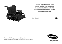
® Adjustable ASBA Seats Invacare® Adjustable ASBA Standard Seat Invacare Adjustable ASBA Power Tilt Only Invacare Adjustable ASBA Formula™ PTO Plus Power Wheelchair Base User Manual EN This manual MUST be given to the user of the product. BEFORE using this product, read this manual and save for - Invacare 3GTQSPBASE | Owners Manual 3 - Page 2
or modification in whole or in part is prohibited without prior written permission from Invacare. Trademarks are identified by ™ and ®. All trademarks are owned by or licensed to Invacare Corporation or its subsidiaries unless otherwise noted. Invacare® Adjustable ASBA Seats 2 Part No 1143192 - Invacare 3GTQSPBASE | Owners Manual 3 - Page 3
3 SAFETY 15 General Guidelines ...15 Operation Information ...16 Setup ...16 Transport...17 Powered Seating...18 Repair or Service Information ...19 Safety/Handling ...20 Pinch Points...21 Stability and Balance ...22 Footplates and Front Rigging...22 Part No 1143192 3 Invacare® Adjustable ASBA - Invacare 3GTQSPBASE | Owners Manual 3 - Page 4
24 Powered Wheelchair Electromagnetic Interference (EMI) ...25 4 TECHNICAL DATA 26 Typical Product Parameters...26 Seat ...26 Weight ...28 5 USAGE 29 Preparing the Joystick for Use...29 A Note About Drive Lock-Out ...30 Operating Powered Seating Systems ...31 Using the Powered Seating Switch - Invacare 3GTQSPBASE | Owners Manual 3 - Page 5
Cantilever Arms ...47 Operating the Manual Recliner Option ...48 Operating the Manual Tilt Option (TDX Spree Only) ...49 6 ADJUSTMENT 51 Footrest Height Adjustment ...51 PH904A and PHAL4A Front Riggings ...51 70° and PW93 ...52 70° Taper...53 Part No 1143192 5 Invacare® Adjustable ASBA Seats - Invacare 3GTQSPBASE | Owners Manual 3 - Page 6
Adjusting the Manual Tilt Front Rigging Support ...67 Installing Adjustable Angle Flip-up Footplate Hinge ...68 Installing Adjustable Angle Flip-up Footplates...69 Composite/Articulating Footplate Heel Loop Replacement ...70 Disassembly ...70 Assembly...70 Invacare® Adjustable ASBA Seats 6 Part - Invacare 3GTQSPBASE | Owners Manual 3 - Page 7
72 CMPJ+ Joysticks ...73 Replacing Seat Positioning Strap...74 Wheelchairs with TRRO Option ...74 Wheelchairs without TRRO Option...74 Removing/ Upholstery...77 Removing/Installing the Manual Tilt Release Lever from the Stroller Handle ...78 Part No 1143192 7 Invacare® Adjustable ASBA Seats - Invacare 3GTQSPBASE | Owners Manual 3 - Page 8
1 General 1.1 Symbols Warnings Signal words are used in this manual and apply to hazards or unsafe practices which could result in personal is not avoided. Gives useful tips, recommendations and information for efficient, trouble-free use. Invacare® Adjustable ASBA Seats 8 Part No 1143192 - Invacare 3GTQSPBASE | Owners Manual 3 - Page 9
to the table below for part numbers of additional documents which are referenced in this manual. MK6i™ Electronics Programming Guide Adjustable ASBA Service Manual PTO Plus Service Manual MANUAL 1 GENERAL PART NUMBER 1141471 1143238 1125031 Part No 1143192 9 Invacare® Adjustable ASBA Seats - Invacare 3GTQSPBASE | Owners Manual 3 - Page 10
assignable to any subsequent purchaser or owner. Coverage under this warranty will end upon any such subsequent sale or other transfer of title to coverage under this warranty. Invacare warrants all electronics and electrical components (excluding batteries) and powered seating actuators to be free - Invacare 3GTQSPBASE | Owners Manual 3 - Page 11
for coverage under this warranty. Invacare warrants all electronics and electrical components (excluding batteries) and powered seating actuators to be free from BY INVACARE. THE WARRANTY SHALL NOT APPLY TO PROBLEMS ARISING FROM NORMAL WEAR AND TEAR OR FAILURE TO ADHERE TO THE PRODUCT INSTRUCTIONS. - Invacare 3GTQSPBASE | Owners Manual 3 - Page 12
base. 2.1 All Wheelchairs Weight Capacity Label located here Serial Number Located HERE Invacare® Adjustable ASBA Seats WA R N I N G Refer to Service Manual to reposition the seat - otherwise serious personal injury and damage will result. P/N 1114823 Rev B - 5/10/06 12 Part No 1143192 - Invacare 3GTQSPBASE | Owners Manual 3 - Page 13
2.2 Wheelchairs with TRRO 2.3 Wheelchairs without TRRO Auto style seat positioning strap shown. This label is also on the airline style seat positioning strap. 2 LABEL LOCATIONS Part No 1143192 13 Invacare® Adjustable ASBA Seats - Invacare 3GTQSPBASE | Owners Manual 3 - Page 14
2 LABEL LOCATIONS 2.4 Pronto® M91™ with Formula PTO Plus Seating System Rear View of Actuator Invacare® Adjustable ASBA Seats 14 Part No 1143192 - Invacare 3GTQSPBASE | Owners Manual 3 - Page 15
with Invacare accessories. Accessories designed by other manufacturers have not been tested by Invacare and are not recommended for use with Invacare products. DO NOT connect any medical devices such as ventilators, life support machines, etc., directly to the batteries used to power the wheelchair - Invacare 3GTQSPBASE | Owners Manual 3 - Page 16
entered during the set-up procedure. If the wheelchair does not perform to specifications, turn the wheelchair Off immediately and reenter set-up specifications. Repeat this procedure until the wheelchair performs to specifications. Invacare® Adjustable ASBA Seats 16 Part No 1143192 - Invacare 3GTQSPBASE | Owners Manual 3 - Page 17
floors. Serious bodily injury may occur. DO NOT attempt to lift the wheelchair by any removable (detachable) parts. Lifting by means of any removable (detachable) parts of a wheelchair may result in injury to the user or damage to the wheelchair. Part No 1143192 17 Invacare® Adjustable ASBA Seats - Invacare 3GTQSPBASE | Owners Manual 3 - Page 18
a tilted position over 20° relative to vertical, DO NOT operate the wheelchair. DO NOT attempt to adjust the drive lock-out. Have the wheelchair serviced by a qualified technician. Use only the controls listed in Using the Powered Seating Switch on page 32 to activate the tilt functions. DO NOT USE - Invacare 3GTQSPBASE | Owners Manual 3 - Page 19
function is not operating and is in the down (seated) position, PRIOR to servicing the device, refer to the seating system service manual, part number 1125031, or contact Invacare Technical Services for instructions on how to safely service the tilt system, actuator or spring assist module. Call - Invacare 3GTQSPBASE | Owners Manual 3 - Page 20
may cause the inside drive wheel to lose traction and the wheelchair to tip over. DO NOT shift your weight or sitting position toward the direction you are reaching as the wheelchair and/or seating system (if any) may tip over. ALWAYS keep hands and fingers clear of moving parts to avoid injury. DO - Invacare 3GTQSPBASE | Owners Manual 3 - Page 21
exists between head tube cap and walking beam. TDX and TDX SP, SR, SI, SC and Spree Wheelchairs Only - A pinch point exists between walking beam/head tube cap and telescoping tube when the seat is in the lowest seat to floor height. POWERED SEATING SYSTEMS ONLY - Pinch point may occur when returning - Invacare 3GTQSPBASE | Owners Manual 3 - Page 22
the presence of a qualified healthcare provider before attempting active use of this wheelchair. Other general warnings listed within this document also apply. DO NOT stand on the frame of the wheelchair. Footplates and Front Rigging ƽ WARNING DO NOT use the footplates as a platform. When getting - Invacare 3GTQSPBASE | Owners Manual 3 - Page 23
Product Parameters in the manual shipped with the wheelchair base to determine the weight limit (total combined weight of user and any attachments) of your wheelchair model. DO NOT exceed the limit - otherwise, injury or damage may result. Part No 1143192 23 Invacare® Adjustable ASBA Seats - Invacare 3GTQSPBASE | Owners Manual 3 - Page 24
and cellular phones. The interference (from radio wave sources) can cause the powered wheelchair to release its brakes, move by itself, or move in unintended directions. It know, are not likely to cause EMI problems to your powered wheelchair. Invacare® Adjustable ASBA Seats 24 Part No 1143192 - Invacare 3GTQSPBASE | Owners Manual 3 - Page 25
occurs, turn the powered wheelchair OFF as soon as it is safe; 4) Be aware that adding accessories or components, or modifying the powered wheelchair, may make it more as manufactured by Invacare may adversely affect the EMI immunity levels. Part No 1143192 25 Invacare® Adjustable ASBA Seats - Invacare 3GTQSPBASE | Owners Manual 3 - Page 26
18 inches Seat-to-Floor Height *16-inch deep frame with AT5544 Legrests FORMULA PTO PLUS 16 to 22 inches 16 to 22 inches 18 to 20 inches ± ¼ inch POWER TILT (Back Post Only) 0° Seat Angle: 18.25 ± .25 inches 5° Seat Angle: 19.25 ± .25 inches Invacare® Adjustable ASBA Seats 26 Part No 1143192 - Invacare 3GTQSPBASE | Owners Manual 3 - Page 27
Nylon Seat Cushion: Cushion (Optional) Front Riggings: Center mount, Swingaway, Manually Elevating, Power Elevating Footrests: Telescoping Front Rigging Supports, 2-inch and 4-inch long Pivot Slide Tube *16-inch deep frame with AT5544 Legrests 4 TECHNICAL DATA FORMULA PTO PLUS POWER TILT - Invacare 3GTQSPBASE | Owners Manual 3 - Page 28
wheelchair now has a 275 lb weight limitation. **Seat Weight: Maximum Weight Limitation ADJUSTABLE ASBA ADULT 43 lbs Up to 400 lbs ADJUSTABLE ASBA JUNIOR 36 lbs Up to 150 lbs FORMULA PTO PLUS 25 lbs Up to 275 lbs Up to 375 lbs (with Spring Assist) POWER TILT ONLY 65 lbs On Torque™ SP systems - Invacare 3GTQSPBASE | Owners Manual 3 - Page 29
adjustment lock lever to secure the adjustment lock to the joystick mounting tube. Joystick Mounting Tube FIGURE 1 Adjustment Lock Lever Preparing the Joystick for Use Part No 1143192 29 Invacare® Adjustable ASBA Seats - Invacare 3GTQSPBASE | Owners Manual 3 - Page 30
attempt to adjust the drive lock-out. Have the wheelchair serviced by a qualified technician. The wheelchair user MUST have a clear line of sight to drive safely. On initial chair delivery and after adjusting the back angle, drive lock-out switch or tilt system, tilt the seat back to the farthest - Invacare 3GTQSPBASE | Owners Manual 3 - Page 31
. DO NOT attempt to adjust the drive lock-out. Have the wheelchair serviced by a qualified technician. Use caution when driving in a tilted position. DO NOT operate the seating system while on an incline. DO NOT operate seating system while the wheelchair is moving. DO NOT operate the tilt function - Invacare 3GTQSPBASE | Owners Manual 3 - Page 32
sure the wheelchair is on a level surface. 2. Press the mode button to switch from driving mode to tilt mode. The LED will light up with a circle around it. 3. Move the joystick: • Forward - Tilts the seat back. • Backward - Tilts the seat upright. Invacare® Adjustable ASBA Seats 32 Part No - Invacare 3GTQSPBASE | Owners Manual 3 - Page 33
Button (Hare) Service Indicator *The mode button is only present on SPJ+ w/ACC joystick. FIGURE 2 Using the MK6i SPJ+ w/ACC Joystick 5 USAGE Joystick Additional Input for Powered Seating Switch Charger/ Programming Input Active (If Programed) Part No 1143192 33 Invacare® Adjustable ASBA - Invacare 3GTQSPBASE | Owners Manual 3 - Page 34
quadrant. 5. Select the desired operation using the joystick or an equivalent switch. While operating the powered seating system, the selected icon will display on the screen along with text indicating the current operation (Detail "C"). Invacare® Adjustable ASBA Seats 34 Part No 1143192 - Invacare 3GTQSPBASE | Owners Manual 3 - Page 35
"B" - ACTUATOR CONTROL SWITCH MODE EXAMPLE SCREEN Operation Icons Tilt Down Icon (Move the joystick down to use this function) DETAIL "C" - EXAMPLE SCREEN DURING POWERED SEATING OPERATION Icon Icon Text Text FIGURE 3 Using the CMPJ+ Joystick Part No 1143192 35 Invacare® Adjustable ASBA - Invacare 3GTQSPBASE | Owners Manual 3 - Page 36
in the same way as the joystick mode switch when the wheelchair is not in motion. Refer to Mode Switch on page 37 Drive Select/On/Off switch must be in the On position. Each activation of the ability switch will alternately turn the joystick On or Off. Invacare® Adjustable ASBA Seats 36 Part - Invacare 3GTQSPBASE | Owners Manual 3 - Page 37
*In these modes, Standby Select allows the reset switch to be bypassed for users unable to activate the switch. Memory Card Slot The memory card slot is used with the basic or professional memory card for saving or reading wheelchair parameters. Part No 1143192 37 Invacare® Adjustable ASBA Seats - Invacare 3GTQSPBASE | Owners Manual 3 - Page 38
front rigging is three inches. If the wheelchair is not moving, the front rigging MUST maintain a minimum of one inch ground clearance - otherwise personal injury and damage may result. DO NOT stand Footrests - Ph904A, Phal4A, 70° and pw93 Invacare® Adjustable ASBA Seats 38 Part No 1143192 - Invacare 3GTQSPBASE | Owners Manual 3 - Page 39
the wheelchair until it locks into place. The footplate will be on the inside of the wheelchair when and raise front rigging to the desired height. • Lowering - Support front rigging with one Part No 1143192 FIGURE 6 Raising/Lowering Elevating Front Riggings 39 Invacare® Adjustable ASBA Seats - Invacare 3GTQSPBASE | Owners Manual 3 - Page 40
of the wheelchair. 2. Lift UP on the legrest and remove from the wheelchair. 3. Repeat STEPS 1- 2 for opposite side of wheelchair. Hinge Pins Hinge Plates Calfpad Legrest Legrest Release Handle Bolt/Nut FIGURE 7 Installing/Removing Elevating Legrests Invacare® Adjustable ASBA Seats 40 Part No - Invacare 3GTQSPBASE | Owners Manual 3 - Page 41
height. • Lowering - Support leg with one hand and avoid interference with the front stabilizers while going over wheelchair. Adjust Calfpad 5 USAGE Secure Calfpad FIGURE 8 Raising/Lowering Elevating Legrests and/or Adjusting Calfpads Part No 1143192 41 Invacare® Adjustable ASBA Seats - Invacare 3GTQSPBASE | Owners Manual 3 - Page 42
to the mounting bracket of the seat frame. Release lever located towards the front or center of seat frame. Rigging Pivot Pin Seat Frame Mounting Bracket Center Mount Footrest FIGURE 9 Removing/Installing the Manual Center Mount Footrest Invacare® Adjustable ASBA Seats 42 Part No 1143192 - Invacare 3GTQSPBASE | Owners Manual 3 - Page 43
the wheelchair until it locks in place. The footplate will be on the INSIDE of the wheelchair when locked in place. 4. Repeat STEPS 1-3 for the opposite legrest. 5. Connect power legrest connector to jumper cable (Detail "B" of FIGURE 10). Part No 1143192 43 Invacare® Adjustable ASBA Seats - Invacare 3GTQSPBASE | Owners Manual 3 - Page 44
wheelchair. 4. Repeat STEPS 1-3 for opposite power legrest. Mounting Hole DETAIL "A" Mounting Pin Calf Pad DETAIL "B" Legrest Release Handle Footplate Jumper Cable Power Legrest Connector FIGURE 10 Installing/Removing the Power Elevating Legrests Invacare® Adjustable ASBA Seats 44 Part - Invacare 3GTQSPBASE | Owners Manual 3 - Page 45
and height adjustment levers are in the locked position before using the wheelchair. Flip back armrest release lever must be in the unlocked ( Up - Horizontal) Seat Frame Quick-Release Pin Front Arm Socket FIGURE 11 Installing/Removing Footrests Part No 1143192 45 Invacare® Adjustable ASBA - Invacare 3GTQSPBASE | Owners Manual 3 - Page 46
levers are in the locked position before using the wheelchair. Positioning Flip Back Armrests for User Transfer 1. Pull up on the flip back armrest and remove the armrest from the front arm socket. 3. Continue to pull up on the flip back armrest Invacare® Adjustable ASBA Seats 46 Part No 1143192 - Invacare 3GTQSPBASE | Owners Manual 3 - Page 47
. 2. Pull the end of the cantilever arm up to move it out of the way. 5 USAGE Cantilever Arm FIGURE 13 Using Non-Locking Cantilever Arms Part No 1143192 47 Invacare® Adjustable ASBA Seats - Invacare 3GTQSPBASE | Owners Manual 3 - Page 48
Make sure the wheelchair is on a level surface. 2. Inform the occupant of the wheelchair that the wheelchair is about to be reclined. 3. Stand behind the wheelchair and grasp both mechanics. Handle Invacare® Adjustable ASBA Seats FIGURE 14 Operating the Manual Recliner Option 48 Part No 1143192 - Invacare 3GTQSPBASE | Owners Manual 3 - Page 49
attempt to adjust the drive lock-out. Have the wheelchair serviced by a qualified technician. The wheelchair user MUST have a clear line of sight to drive safely. On initial chair delivery and after adjusting the back angle, drive lock-out switch or tilt system, tilt the seat back to the farthest - Invacare 3GTQSPBASE | Owners Manual 3 - Page 50
the two release levers to engage the manual tilt system. Wheelchair Base Seat Assembly in Tilted Position Tilt (Right) Release Lever Seat Lock (Left) Release Lever Stroller Handle FIGURE 15 Operating the Manual Tilt Option (TDX Spree Only) Invacare® Adjustable ASBA Seats 50 Part No 1143192 - Invacare 3GTQSPBASE | Owners Manual 3 - Page 51
STEPS 1-3 for the opposite side of the wheelchair footrest, if necessary. PH904A style front rigging shown. PHAL4A front rigging adjusts the same way. Footrest Support Locknut Lower Footrest Lug Bolt FIGURE 1 Footrest Height Adjustment Part No 1143192 51 Invacare® Adjustable ASBA Seats - Invacare 3GTQSPBASE | Owners Manual 3 - Page 52
onto the wheelchair. Refer to Installing/ Removing Footrests on page 38. 8. Reinstall any accessory onto the footrest(s). Footrest Support Locknut Coved Washer Coved Washer Hex Bolt Lower Footrest FIGURE 2 Footrest Height Adjustment - 70° and PW93 Invacare® Adjustable ASBA Seats 52 Part No - Invacare 3GTQSPBASE | Owners Manual 3 - Page 53
the frame mounting tubes. 6. Reinstall the footrest(s) onto the wheelchair. Refer to Installing/ Removing Footrests on page 38. 7. Reinstall any accessory onto the footrest(s). Heel Loop Footrest FIGURE 3 Footrest Height Adjustment - 70° Taper Part No 1143192 53 Invacare® Adjustable ASBA Seats - Invacare 3GTQSPBASE | Owners Manual 3 - Page 54
Retighten the two flat screws, washers and locknuts. 90° Footrest Support Flat Screw Footplate Half Clamp Washer Locknut Half Clamp Footplate Hinge Nylon Adjustment Screw Footplate Hinge FIGURE 4 Adjusting Adjustable Angle Flip-Up Footplates Invacare® Adjustable ASBA Seats 54 Part No 1143192 - Invacare 3GTQSPBASE | Owners Manual 3 - Page 55
Footrest Support Footplate 6 ADJUSTMENT Side View of Footplate and Footrest Support FIGURE 5 Angle Adjustment Front View of Footplate and Footrest Support Footrest Support Footplate FIGURE 6 Perpendicular and/or Inversion/Eversion Adjustment Part No 1143192 55 Invacare® Adjustable ASBA Seats - Invacare 3GTQSPBASE | Owners Manual 3 - Page 56
Manual Center Mount Footrest ƽ WARNING While the wheelchair is moving, minimum ground clearance for the front rigging is three inches. If the wheelchair is not moving, the front Invacare® Adjustable ASBA Seats FIGURE 7 Adjusting the Height of the Manual Center Mount Footrest 56 Part No - Invacare 3GTQSPBASE | Owners Manual 3 - Page 57
Manual Center Mount Footrest 6 ADJUSTMENT ƽ WARNING While the wheelchair is moving, minimum ground clearance for the front rigging is three inches. If the wheelchair is not moving, the front the Angle of the Manual Center Mount Footrest Part No 1143192 57 Invacare® Adjustable ASBA Seats - Invacare 3GTQSPBASE | Owners Manual 3 - Page 58
the adjustment screw in or out until the desired angle is achieved. 3. Repeat STEPS 1 and 2 for the other footplate. Manual Center Mount Footrest Footplate (shown away from Extension Tube) Adjustment Screw FIGURE 9 Adjusting the Footplate Angle Invacare® Adjustable ASBA Seats 58 Part No 1143192 - Invacare 3GTQSPBASE | Owners Manual 3 - Page 59
arm (as necessary). Center Mount Front Rigging 6 ADJUSTMENT Footplate Mounting Screw FIGURE 10 Adjusting the Tension of the Flip Up Footplate Back Cane Arm Tube Arm Pad Part No 1143192 Adjustment Screw FIGURE 11 Adjusting the Angle of the Cantilever Arm 59 Invacare® Adjustable ASBA Seats - Invacare 3GTQSPBASE | Owners Manual 3 - Page 60
the back canes. 5. Torque the locknuts to 13 ft-lbs. DETAIL "A" - CANE BRACKET MOUNTING HOLES Back Cane Locknut 95° 85° 90° Cane Bracket 105° 100° Invacare® Adjustable ASBA Seats Upper Hex Screw Washer Lower Hex Screw FIGURE 12 Adjusting the Back Angle 60 - Invacare 3GTQSPBASE | Owners Manual 3 - Page 61
upholstery. 6 ADJUSTMENT Tilt Cylinders Jam Nut Jam Nut Cable Adjuster Cable Adjuster FIGURE 13 Adjusting the Manual Tilt Cable Assembly Headrest Upholstery Spreader Bar Back Upholstery Part No 1143192 FIGURE 14 Adjusting Back or Headrest Upholstery 61 Invacare® Adjustable ASBA Seats - Invacare 3GTQSPBASE | Owners Manual 3 - Page 62
, and as necessary, take your wheelchair to a qualified technician for a thorough inspection and servicing. Refer to Service Inspection on page 64. Refer to wheelchair base user manual for additional safety inspection and troubleshooting information. Check all parts for shipping damage. In case - Invacare 3GTQSPBASE | Owners Manual 3 - Page 63
vehicle. Routine maintenance will extend the life and efficiency of your wheelchair. Refer to wheelchair base user manual for additional safety inspection and troubleshooting information. ƽ CAUTION As with any vehicle, the wheels and tires should be checked periodically for cracks and wear, and - Invacare 3GTQSPBASE | Owners Manual 3 - Page 64
all electrical connections are secure. Powered Seating Systems - Make sure drive lock-out operates properly. Powered Seating Systems - Make sure tilt mechanism and tilt tracks are clean. 7.3 Service Inspection Every six months take your wheelchair to a qualified technician for a thorough - Invacare 3GTQSPBASE | Owners Manual 3 - Page 65
service inspection may vary according to the specific wheelchair mount front riggings for Powered Seating Systems - Make sure all electrical connections are secure. Powered Seating Systems - Make sure drive lock-out operates properly. Check limit switch position. Part No 1143192 65 Invacare - Invacare 3GTQSPBASE | Owners Manual 3 - Page 66
When securing heel loop to lower footrest, tighten the phillips screw and locknut until the spacer is secure. Locknut Coved Washer Footrest Support Hex Bolt Phillips Bolt Spacer Lower Footrest Heel Loop Locknut FIGURE 1 Replacing Heel Loops Invacare® Adjustable ASBA Seats 66 Part No 1143192 - Invacare 3GTQSPBASE | Owners Manual 3 - Page 67
and threaded blocks. 4. Repeat STEPS 1 to 3 on the opposite side, if desired. Side Rail Spacers Cap Screws Part No 1143192 Side Rail Cap Screws Spacers Threaded Blocks Telescoping Front Tube FIGURE 2 Adjusting/Replacing Telescoping Front Rigging Support 67 Invacare® Adjustable ASBA Seats - Invacare 3GTQSPBASE | Owners Manual 3 - Page 68
and down motion of the footplate hinge to make sure the user of the wheelchair can operate the footplates easily. If footplate's motion is too tight, Spacer Footrest Support FIGURE 3 Installing Adjustable Angle Flip-up Footplate Hinge Invacare® Adjustable ASBA Seats 68 Part No 1143192 - Invacare 3GTQSPBASE | Owners Manual 3 - Page 69
-Up Footplates on page 54. 7 SETUP/MAINTENANCE 90° Footrest Support Flat Screw Footplate Half Clamp Washer Locknut Footplate Hinge Nylon Adjustment Screw Half Clamp Footplate Hinge FIGURE 4 Installing Adjustable Angle Flip-up Footplates Part No 1143192 69 Invacare® Adjustable ASBA Seats - Invacare 3GTQSPBASE | Owners Manual 3 - Page 70
mounting screw until the spacer is secure. Composite Cane of Footrest Assembly Mounting Screw Spacer Composite Footplate Locknut Articulating Mounting Screw Invacare® Adjustable ASBA Seats Heel Loop Articulating Footplate FIGURE 5 Composite/Articulating Footplate Heel Loop Replacement 70 - Invacare 3GTQSPBASE | Owners Manual 3 - Page 71
the joystick mounting tube from the mounting bracket. 2. Remove the joystick from the wheelchair. 3. Remove the three hex screws that secure both halves of the mounting bracket not shown. FIGURE 6 Repositioning Joystick Joystick Mounting Tube Part No 1143192 71 Invacare® Adjustable ASBA Seats - Invacare 3GTQSPBASE | Owners Manual 3 - Page 72
hand and the controller connector on the wheelchair in the other and align them. 2. Lightly push to engage the joystick connector and the controller connector. Joystick Connector FIGURE 7 Disconnecting/Connecting the Joysticks - SPJ+ Joysticks Invacare® Adjustable ASBA Seats 72 Part No 1143192 - Invacare 3GTQSPBASE | Owners Manual 3 - Page 73
tie-wraps. Top Connector Cap Network Connectors 7 SETUP/MAINTENANCE Latch Gasket Controller Cable Gasket Bottom Connector Cap Gasket FIGURE 8 Disconnecting/Connecting the Joysticks - CMPJ+ Joysticks Part No 1143192 73 Invacare® Adjustable ASBA Seats - Invacare 3GTQSPBASE | Owners Manual 3 - Page 74
pan. Mounting Holes Seat Frame Mounting Screw Locknuts Mounting Screw Seat Frame Quick-Release Pin Tab Washers Quick-Release Pin Tab Seat Positioning Strap Halves FIGURE 9 Replacing Seat Positioning Strap - Wheelchairs without TRRO Option Invacare® Adjustable ASBA Seats 74 Part No 1143192 - Invacare 3GTQSPBASE | Owners Manual 3 - Page 75
/Adjusting Headrest 7 SETUP/MAINTENANCE ƽ CAUTION If using a ventilator, verify headrest support does not interfere at all angles. Otherwise, injury or damage may occur. Headrest Stop FIGURE 10 Removing/Installing/Adjusting Headrest Part No 1143192 75 Invacare® Adjustable ASBA Seats - Invacare 3GTQSPBASE | Owners Manual 3 - Page 76
the desired depth by sliding the headrest towards the front of the wheelchair or towards the rear of the wheelchair. 3. If necessary, reposition the headrest to the desired Mounting Bracket Socket Screw Headrest Invacare® Adjustable ASBA Seats FIGURE 11 Replacing Headrest 76 Part No 1143192 - Invacare 3GTQSPBASE | Owners Manual 3 - Page 77
Adjusting Back or Headrest Upholstery on page 61. 7 SETUP/MAINTENANCE Headrest Upholstery Headrest Extension Mounting Screw Back Cane Back Upholstery FIGURE 12 Replacing Headrest Upholstery Part No 1143192 77 Invacare® Adjustable ASBA Seats - Invacare 3GTQSPBASE | Owners Manual 3 - Page 78
Manual Tilt Cable Assembly on page 61. Stroller Handle Mounting Screw Cable DETAIL "A" Back Cane Tie-Wrap Tilt Release Lever Square Nut Tilt Release Lever Tie-Wrap FIGURE 13 Removing/Installing the Manual Tilt Release Lever from the Stroller Handle Invacare® Adjustable ASBA Seats 78 Part - Invacare 3GTQSPBASE | Owners Manual 3 - Page 79
7 SETUP/MAINTENANCE Notes Invacare® Adjustable ASBA Seats 79 Part No 1143192 - Invacare 3GTQSPBASE | Owners Manual 3 - Page 80
Part No 1143192 Rev H - 5/11 Invacare Corporation USA One Invacare Way Elyria, Ohio USA 44036-2125 800-333-6900 www.invacare.com Canada 570 Matheson Blvd E Unit 8 Mississauga Ontario L4Z 4G4 Canada 800-668-5324
-
 1
1 -
 2
2 -
 3
3 -
 4
4 -
 5
5 -
 6
6 -
 7
7 -
8
-
9
-
10
-
11
-
12
-
13
-
14
-
15
-
16
-
17
-
18
-
19
-
20
-
21
-
22
-
23
-
24
-
25
-
26
-
27
-
28
-
29
-
30
-
31
-
32
-
33
-
34
-
35
-
36
-
37
-
38
-
39
-
40
-
41
-
42
-
43
-
44
-
45
-
46
-
47
-
48
-
49
-
50
-
51
-
52
-
53
-
54
-
55
-
56
-
57
-
58
-
59
-
60
-
61
-
62
-
63
-
64
-
65
-
66
-
67
-
68
-
69
-
70
-
71
-
72
-
73
-
74
-
75
-
76
-
77
-
78
-
79
-
80
 |
 |
This manual MUST be given to the user of the product.
BEFORE using this product, read this manual and save for future reference.
User Manual
EN
Invacare
®
Adjustable ASBA Seats
Invacare
®
Adjustable ASBA Standard Seat
Invacare
Adjustable ASBA
Power Tilt Only
Invacare
Adjustable ASBA
Formula™ PTO Plus
Power Wheelchair Base