Invacare 9153637774 Owners Manual
Invacare 9153637774 Manual
 |
View all Invacare 9153637774 manuals
Add to My Manuals
Save this manual to your list of manuals |
Invacare 9153637774 manual content summary:
- Invacare 9153637774 | Owners Manual - Page 1
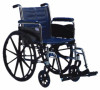
User Manual EN Invacare® Tracer™ EX2 Wheelchair This manual MUST be given to the user of the product. BEFORE using this product, read this manual and save for future reference. - Invacare 9153637774 | Owners Manual - Page 2
part is prohibited without prior written permission from Invacare. Trademarks are identified by ™ and ®. All trademarks are owned by or licensed to Invacare Corporation or its subsidiaries unless otherwise noted. Teflon is a registered trademark of DuPont. Invacare® Tracer™ EX2 Wheelchair 2 Part - Invacare 9153637774 | Owners Manual - Page 3
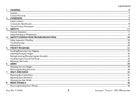
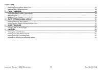
...11 Safety/Handling of Wheelchairs...18 4 SAFETY INSPECTION/TROUBLESHOOTING 25 Safety Inspection Checklist ...25 Troubleshooting...28 Maintenance ...29 5 FRONT Seat Width ...42 8 REAR WHEELS 46 Removing/Installing Rear Wheels...46 Part No 1110546 3 Invacare® Tracer™ EX2 Wheelchair - Invacare 9153637774 | Owners Manual - Page 4
OPTIONS 59 Installing Amputee Bracket...59 Installing Crutch and Cane Carrier...61 Installing the Seat Positioning Strap ...62 Installing the Wheel Lock Extension Handle...63 Invacare® Tracer™ EX2 Wheelchair 4 Part No 1110546 - Invacare 9153637774 | Owners Manual - Page 5
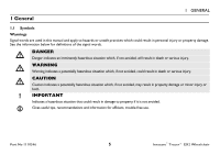
1 GENERAL 1.1 Symbols Warnings Signal words are used in this manual and apply to hazards or unsafe practices which could result in personal it is not avoided. Gives useful tips, recommendations and information for efficient, trouble-free use. Part No 1110546 5 Invacare® Tracer™ EX2 Wheelchair - Invacare 9153637774 | Owners Manual - Page 6
any labor or shipping charges incurred in replacement part installation or repair of any such product. Invacare's sole obligation and your exclusive remedy under this warranty shall be limited to such repair and/or replacement. For warranty service, please contact the dealer from whom you purchased - Invacare 9153637774 | Owners Manual - Page 7
attaches at the left hip. 2 OVERVIEW Crossmember Part No 1110546 On all adjustable anti-tippers ! WARNING Refer to the Owner's Manual for proper anti-tipper setting. ! AVERTISSEMENT Se d'abord avoir installé les antibascules. No. 1091552 Lower Frame Tube 7 Invacare® Tracer™ EX2 Wheelchair - Invacare 9153637774 | Owners Manual - Page 8
2 OVERVIEW 2.1 Component Identification Back Upholstery Rear Wheel Handrim Rear Wheel Axle Wheel Lock Seat Upholstery Wheelchair Frame Front Caster Invacare® Tracer™ EX2 Wheelchair 8 Part No 1110546 - Invacare 9153637774 | Owners Manual - Page 9
FF Frame) Hemi: (SA Frame) Back Style Back Height Arm Styles Front Riggings Rear Axle Rear Wheels Handrims Part No 1110546 2 OVERVIEW Tracer EX2 231/4, 251/4, 271/4 inches 241/4, 261/4, 281/4 inches 317/8 inches Permanent 24-inch Composite or Urethane Composite 9 Invacare® Tracer™ EX2 Wheelchair - Invacare 9153637774 | Owners Manual - Page 10
are based on urethane tires. These heights can vary +/- 1/4 inch due to tire wear and manufacturing tolerances. *** - Weights based on 18-inch wide wheelchair without front riggings. Weights will vary depending on how the wheelchair is equipped. Invacare® Tracer™ EX2 Wheelchair 10 Part No 1110546 - Invacare 9153637774 | Owners Manual - Page 11
Invacare products. NOTICE THE INFORMATION CONTAINED IN THIS DOCUMENT IS SUBJECT TO CHANGE WITHOUT NOTICE. Check all parts for shipping damage and test before using. In case of damage, DO NOT use. Contact Invacare/Carrier for further instruction. Part No 1110546 11 Invacare® Tracer™ EX2 Wheelchair - Invacare 9153637774 | Owners Manual - Page 12
Refer to the chart in this section of the manual for correct usage and adjustment. If these requirements cannot be achieved, DO NOT use the wheelchair. Contact a qualified technician. If changing the seat- are adjusted to the same mounting hole. Invacare® Tracer™ EX2 Wheelchair 12 Part No 1110546 - Invacare 9153637774 | Owners Manual - Page 13
on roads, streets or highways. DO NOT allow children to play on or operate the wheelchair. DO NOT operate on soft surfaces such as sand, grass, or gravel. DO NOT overtighten hardware attaching to the frame. This could cause damage to the frame tubing. Part No 1110546 13 Invacare® Tracer™ EX2 - Invacare 9153637774 | Owners Manual - Page 14
it alone. Lifting ƽ WARNING DO NOT attempt to lift the wheelchair by any removable (detachable) parts. Lifting by means of any removable (detachable) parts of the wheelchair may result in injury to the user or damage to the wheelchair. Invacare® Tracer™ EX2 Wheelchair 14 Part No 1110546 - Invacare 9153637774 | Owners Manual - Page 15
wheelchair. NEVER leave an unoccupied wheelchair on an incline. DO NOT attempt to stop the wheelchair while on a sloped surface. Repair and Service Information ƽ WARNING Unless otherwise noted, all service in the event of a fall from a wheelchair. Part No 1110546 15 Invacare® Tracer™ EX2 - Invacare 9153637774 | Owners Manual - Page 16
SIZE CASTER POSITION WHEEL SIZE WHEEL POSITION ANTI-TIPPERS USER CONDITION Weight Limitation ƽ WARNING The Tracer EX2 has a weight limitation of 250 pounds (114 kg). • • • • • Invacare® Tracer™ EX2 Wheelchair 16 Part No 1110546 - Invacare 9153637774 | Owners Manual - Page 17
. It is Invacare's position that users of wheelchairs should be transferred into appropriate seating in vehicles for transportation and use be made of the restraints made available by the auto industry. Invacare cannot and does not recommend any wheelchair transportation systems. Part No 1110546 - Invacare 9153637774 | Owners Manual - Page 18
only as a basic guide. The techniques that are discussed on the following pages have been used successfully by many. Individual wheelchair users often develop skills to deal with daily living activities that may differ from those described in this manual. Invacare recognizes and encourages each - Invacare 9153637774 | Owners Manual - Page 19
wheelchair and then reversing it in a straight line. Many activities require the wheelchair owner to reach, bend and transfer in and out of the wheelchair wheelchair. wheelchair are reaching as the wheelchair may tip over. cause the wheelchair to tip over. Backwards Position wheelchair as close - Invacare 9153637774 | Owners Manual - Page 20
should be positioned at the front of the wheelchair lifting upward on a non-removable (nondetachable) part of the wheelchair frame when lifting the wheelchair and stabilizing the wheelchair when the wheelchair is being lowered to the ground. Invacare® Tracer™ EX2 Wheelchair 20 Part No 1110546 - Invacare 9153637774 | Owners Manual - Page 21
, the user be removed from the wheelchair prior to moving. Invacare recommends using two assistants and making thorough preparations. Make sure to use only secure, non-detachable parts for hand-held supports. Follow this procedure for moving the wheelchair between floors when an elevator is not - Invacare 9153637774 | Owners Manual - Page 22
wheelchair), with a firm hold on a non-detachable part of the framework, lowers the wheelchair down and on to the next stair below and steadies the wheelchair wheelchair should not be lowered until the last stair has been negotiated and the wheelchair move a wheelchair between the wheelchair, every - Invacare 9153637774 | Owners Manual - Page 23
DO NOT sit or transfer into the wheelchair unless it is fully open and the seat frame rails are fully seated into the side frame H-blocks. Unfolding 1. Tilt the wheelchair toward you (raising the opposite wheel and caster off the ground/floor). Part No 1110546 23 Invacare® Tracer™ EX2 Wheelchair - Invacare 9153637774 | Owners Manual - Page 24
edge and lift up. 4. Continue to close the wheelchair by grasping the armrest furthest from you and pulling the armrest towards you. Press DOWN on Seat Rail FIGURE 6 Unfolding and Folding Wheelchair FIGURE 7 Folding Hammock or Sling Seat Models Invacare® Tracer™ EX2 Wheelchair 24 Part No 1110546 - Invacare 9153637774 | Owners Manual - Page 25
Inspection/Troubleshooting 4 SAFETY INSPECTION/TROUBLESHOOTING Every six months or as necessary, take your wheelchair to a qualified technician for a thorough inspection and servicing. Regular cleaning will reveal loose or worn parts and enhance the smooth operation of your wheelchair. To - Invacare 9153637774 | Owners Manual - Page 26
4 SAFETY INSPECTION/TROUBLESHOOTING ƽ WARNING As with any vehicle, check the wheels and tires periodically for cracks and wear. Replace if . ❑ Inspect rear wheels for cracked, bent or broken spokes. ❑ Ensure all spokes are uniformly tight. Invacare® Tracer™ EX2 Wheelchair 26 Part No 1110546 - Invacare 9153637774 | Owners Manual - Page 27
or peeling. ❑ Adjust front casters/forks bearing system if wheel wobbles noticeably or binds to a stop. ❑ Ensure wheel bearings are clean and free of moisture. Part No 1110546 27 Invacare® Tracer™ EX2 Wheelchair - Invacare 9153637774 | Owners Manual - Page 28
water. ❑ Check that all labels are present and legible. Replace if necessary. 4.2 Troubleshooting Chair Veers Right/Left Chair 3 Wheels X X X X X X Sluggish Turn angle. Check that rear wheels are equally spaced away from seat frame. Invacare® Tracer™ EX2 Wheelchair 28 Part No 1110546 - Invacare 9153637774 | Owners Manual - Page 29
4.3 Maintenance 4 SAFETY INSPECTION/TROUBLESHOOTING Maintenance Safety Precautions ƽ WARNING After any adjustments, repair or service and before use, make sure all attaching hardware to Adjusting Patient Operated Wheel Locks on page 55. Part No 1110546 29 Invacare® Tracer™ EX2 Wheelchair - Invacare 9153637774 | Owners Manual - Page 30
the complete wheel assembly. Replacing/Repairing Caster Tire/Tube ƽ WARNING Replacement of solid rubber tires is not recommended. If the solid ribber tires need replaced, Invacare recommends replacing complete caster assembly. Invacare® Tracer™ EX2 Wheelchair 30 Part No 1110546 - Invacare 9153637774 | Owners Manual - Page 31
Front Riggings 5 FRONT RIGGINGS ƽ WARNING After any adjustments, repair or service and before use, make sure all attaching hardware is tightened securely - assembly outward. 3. Lift the swingaway front rigging assembly off the hinge pins. Part No 1110546 31 Invacare® Tracer™ EX2 Wheelchair - Invacare 9153637774 | Owners Manual - Page 32
5 FRONT RIGGINGS Hinge Pins Front Rigging Release Lever Front Rigging Assembly Hinge Plates Footplate Swingaway footrest shown FIGURE 1 Installing/Removing Front Riggings Invacare® Tracer™ EX2 Wheelchair 32 Part No 1110546 - Invacare 9153637774 | Owners Manual - Page 33
Refer to Installing/ Removing Front Riggings on page 31. 5 FRONT RIGGINGS Front Rigging Support Adjustment Holes Cam Lock Lever Release Button Footplate Assembly Swingaway footrest shown FIGURE 2 Adjusting Footplate Height - Spring Button Part No 1110546 33 Invacare® Tracer™ EX2 Wheelchair - Invacare 9153637774 | Owners Manual - Page 34
Hole Front Rigging Support Button Head Screw Threaded Rivet Button Head Screw Cam Lock Lever Adjustment Hole Threaded Rivet Footplate Assembly Footplate Assembly Inside of Swingaway Front Rigging Outside of Swingaway Front Rigging Invacare® Tracer™ EX2 Wheelchair FIGURE 3 Adjusting - Invacare 9153637774 | Owners Manual - Page 35
, lower user leg down and rest against the legrest. Part No 1110546 35 5 FRONT RIGGINGS Wheelchair Frame Footplate Assembly Bolt and Locknut FIGURE 4 Adjusting Footplate Height - Fixed Frame Release Lever Support Tube FIGURE 5 Raising/Lowering Elevating Legrest Assembly Invacare® Tracer™ EX2 - Invacare 9153637774 | Owners Manual - Page 36
of the calf strap around each footrest (with the impact guards attached, if present). Calf Strap Footrest Upper Portion of Impact Guard Horizontal Support Horizontal Support Notch Impact Guard FIGURE 6 Installing Impact Guards/Calf Strap Invacare® Tracer™ EX2 Wheelchair 36 Part No 1110546 - Invacare 9153637774 | Owners Manual - Page 37
Remove the threaded rivet and button head screw securing the footplate assembly to the front rigging support. 3. Remove the mounting screw, spacer and locknut that secure the heel loop to the 9. Rotate cam lock lever down to locked position. Part No 1110546 37 Invacare® Tracer™ EX2 Wheelchair - Invacare 9153637774 | Owners Manual - Page 38
Rigging Support Button Head Screw Front Rigging Support Threaded Rivet Inside of Swingaway Front Rigging Footplate Assembly Cam Lock Lever Adjustment Hole Cam Lock Lever Footplate Assembly Outside of Swingaway Front Rigging Heel Loop Slide Tube Invacare® Tracer™ EX2 Wheelchair Locknut - Invacare 9153637774 | Owners Manual - Page 39
the height adjustment lever into the down (vertical) position when the desired armrest height is achieved. 4. Repeat STEPS 1-3 for the other armrest. Height Adjustment Lever Part No 1110546 Unlocked (Horizontal) FIGURE 1 Adjusting Armrest Height 39 Invacare® Tracer™ EX2 Wheelchair - Invacare 9153637774 | Owners Manual - Page 40
WARNING Make sure the height adjustment lever is in the locked position before using the wheelchair. Removing Armrest 1. Push down on armrest to ensure it is fully seated in Release Button Front Arm Socket Invacare® Tracer™ EX2 Wheelchair FIGURE 2 Removing/Installing Armrests 40 Part No 1110546 - Invacare 9153637774 | Owners Manual - Page 41
Seat and Back ƽ WARNING After any adjustments, repair or service and before use, make sure all attaching hardware is tightened Back Upholstery Mounting Screw 16-inch Seat Depth Seat Upholstery Wheelchair Frame Part No 1110546 FIGURE 2 Replacing Seat Upholstery 41 Invacare® Tracer™ EX2 - Invacare 9153637774 | Owners Manual - Page 42
the seat width of the wheelchair, the back and seat upholstery from the wheelchair. Refer to to the wheelchair frame and the wheelchair frame. wheelchair frame using the washer on the underside of the wheelchair to the wheelchair frame. Refer upholstery onto the wheelchair. Refer to Replacing - Invacare 9153637774 | Owners Manual - Page 43
Saddle (STEPS 3,8) See Detail "A" Part No 1110546 Locknut (STEPS 2,7) Button Screw (STEPS 2,7) Button Screw (STEPS 3,8) Wheelchair Frame Locknut Crossbrace Saddle (STEPS 3,8) (STEPS 3,8) See Detail "B" FIGURE 4 Adjusting the Seat Width - Swingaway Front Riggings 43 Invacare® Tracer™ EX2 - Invacare 9153637774 | Owners Manual - Page 44
Coved Washers Washer Coved Washer DETAIL "A" Wheelchair Frame Washer Crossbraces Coved Washers Hex Screw DETAIL "B" - CROSSBRACE HARDWARE (STEPS 4,5) Washer Crossbrace Saddle FIGURE 5 Adjusting the Seat Width - Swingaway Front Riggings Invacare® Tracer™ EX2 Wheelchair 44 Part No 1110546 - Invacare 9153637774 | Owners Manual - Page 45
DETAIL "B" - REMOVING UPPER MOUNTING HARDWARE DETAIL "A" - REMOVING LOWER MOUNTING HARDWARE Locknut Crossbrace Rear Seat Guide Insert Tube Front Seat Guide Part No 1110546 Crossbrace Hex Screw Screw FIGURE 6 Adjusting the Seat Width - Fixed Frame Wheelchair Frame 45 Invacare® Tracer™ EX2 - Invacare 9153637774 | Owners Manual - Page 46
REAR WHEELS 8 Rear Wheels ƽ WARNING After any adjustments, repair or service and before use, make sure all attaching hardware is tightened securely - the same respective mounting hole before using the wheelchair, otherwise injury may occur. Invacare® Tracer™ EX2 Wheelchair 46 Part No 1110546 - Invacare 9153637774 | Owners Manual - Page 47
), spacer (if installed) and locknut that secure the rear wheel to the wheelchair frame. The spacer is used on wheelchairs with removable arms only. 2. Repeat STEP 1 for the opposite rear wheel for cracks and wear. Replace if damaged. Part No 1110546 47 Invacare® Tracer™ EX2 Wheelchair - Invacare 9153637774 | Owners Manual - Page 48
clean. 5. Reinstall rear wheel to the wheelchair. Refer to Removing/Installing Rear Wheels on page 46. 6. Repeat STEPS 1-5 for the opposite rear wheel if necessary. Handrim Rear Wheel Mounting Screw FIGURE 2 Replacing Rear Wheel Handrim Invacare® Tracer™ EX2 Wheelchair 48 Part No 1110546 - Invacare 9153637774 | Owners Manual - Page 49
. 7. Adjust the forks. Refer to Adjusting Forks on page 50. Dust Cover Locknut Nylon Washer Caster Headtube Fork Assembly FIGURE 1 Installing/Replacing Front Casters/Forks Part No 1110546 49 Invacare® Tracer™ EX2 Wheelchair - Invacare 9153637774 | Owners Manual - Page 50
the same size and are installed into the same respective mounting hole before using the wheelchair, otherwise injury may occur. Note the mounting position on the fork assembly (if applicable) Front Caster FIGURE 2 Replacing Front Casters Invacare® Tracer™ EX2 Wheelchair 50 Part No 1110546 - Invacare 9153637774 | Owners Manual - Page 51
ƽ WARNING After any adjustments, repair or service and before use, make sure all attaching this section of the manual for correct usage and adjustment. If these requirements cannot be achieved, DO NOT use the wheelchair. Contact a qualified Part No 1110546 51 Invacare® Tracer™ EX2 Wheelchair - Invacare 9153637774 | Owners Manual - Page 52
-Tipper Wheels Anti-Tipper Anti-Rattle 3. Place the wheelchair on a flat surface. 4. Measure the distance between the bottom of the anti-tipper wheels and the ground/floor. Release Buttons Rear Frame Tubing FIGURE 2 Installing Anti-Tippers Invacare® Tracer™ EX2 Wheelchair 52 Part No 1110546 - Invacare 9153637774 | Owners Manual - Page 53
is 11/2 to 2 inches. 7. If the 11/2 to 2 inch distance cannot be achieved, a different model may be required. Contact an Invacare dealer or qualified technician. Release Buttons 11/2 to 2 inch Clearance FIGURE 3 Adjusting the Anti-Tippers Part No 1110546 53 Invacare® Tracer™ EX2 Wheelchair - Invacare 9153637774 | Owners Manual - Page 54
this procedure. Ensure the wheelchair is not moving before engaging the wheel locks. 1. See Detail "A" for instructions on Push-to-Lock. Refer to Detail "B" for instructions on Pull-to-Lock. -To-Lock FIGURE 4 Using Patient Operated Wheel Locks Invacare® Tracer™ EX2 Wheelchair 54 Part No 1110546 - Invacare 9153637774 | Owners Manual - Page 55
wheelchair tire. Position wheelchair on a flat assembly to the wheelchair frame. 3. Reposition wheelchair in place when pushed. 4. Securely tighten the bolt and locknut attaching the wheel lock to the wheelchair tires) and holds the wheelchair in place when pushed. lock to the wheelchair frame and mount - Invacare 9153637774 | Owners Manual - Page 56
10 ANTI-TIPPERS/WHEEL LOCKS Bolt and Locknut Wheel Lock Handle Mounting Positions Rear Wheel Wheel Lock Wheel Lock Shoe DETAIL "A" 1/8 inch (3/16 inch pneumatic tires) Wheel Lock Shoe Tire FIGURE 5 Using Patient Operated Wheel Locks Invacare® Tracer™ EX2 Wheelchair 56 Part No 1110546 - Invacare 9153637774 | Owners Manual - Page 57
service and before use, make sure all attaching hardware is tightened securely - otherwise injury or damage may occur. The seat-to-floor height is not adjustable for the Tracer EX2 wheelchair wheels from the wheelchair. Refer to Removing rear wheels onto the wheelchair in the mounting position - Invacare 9153637774 | Owners Manual - Page 58
/HEMI FRAME STYLE DETAIL "B" - 8 INCH FORK MOUNTING POSITIONS Top Bottom FIGURE 1 Changing Seat-to-Floor Height REAR WHEEL MOUNTING POSITION Top Bottom Top Middle Bottom Invacare® Tracer™ EX2 Wheelchair 58 Part No 1110546 - Invacare 9153637774 | Owners Manual - Page 59
any adjustments, repair or service and before use, make sure wheelchair. 3. Install the two hex screws and locknuts that secure the amputee bracket to the wheelchair. 4. Install the rear wheels onto the wheelchair. Refer to Removing/Installing Rear Wheels on page 46. Part No 1110546 59 Invacare - Invacare 9153637774 | Owners Manual - Page 60
OPTIONS Bracket "A" Locknuts Bracket "B" Adult Right Axle Spacer Toward Outside of Wheelchair Left Right Rear View of Amputee Bracket Adult Left Axle Spacer Toward Outside of Wheelchair Hemi Left Invacare® Tracer™ EX2 Wheelchair Hex Screws FIGURE 1 Installing Amputee Bracket 60 Hemi Right - Invacare 9153637774 | Owners Manual - Page 61
interference with folding the wheelchair, the rear wheels, the wheelchair. Ensure the base is towards the inside of the wheelchair. 2. wheelchair. 3. Securely tighten the locknut that secures the base to the step tube of the wheelchair and secure the strap to the wheelchair. 7. The base cleans easily - Invacare 9153637774 | Owners Manual - Page 62
to the wheelchair with the existing back upholstery screw. 4. Repeat STEPS 1-3 for the opposite side of the wheelchair. Back Upholstery Screw Back Cane Back Upholstery Strap Positioning Strap FIGURE 3 Installing the Seat Positioning Strap Invacare® Tracer™ EX2 Wheelchair 62 Part No 1110546 - Invacare 9153637774 | Owners Manual - Page 63
the extension handle over the wheel lock handle (Detail "B"). Detail "A" Rubber Tip Detail "B" Wheel Lock Extension Handle Wheel Lock Handle Wheel Lock Handle Wheel Lock Part No 1110546 Wheel Lock FIGURE 4 Installing the Wheel Lock Extension Handle 63 Invacare® Tracer™ EX2 Wheelchair - Invacare 9153637774 | Owners Manual - Page 64
Part No 1110546 Rev G - 2/11 Invacare Corporation USA One Invacare Way Elyria, Ohio USA 44036-2125 800-333-6900 www.invacare.com Canada 570 Matheson Blvd E Unit 8 Mississauga Ontario L4Z 4G4 Canada 800-668-5324
-
 1
1 -
 2
2 -
 3
3 -
 4
4 -
 5
5 -
 6
6 -
 7
7 -
8
-
9
-
10
-
11
-
12
-
13
-
14
-
15
-
16
-
17
-
18
-
19
-
20
-
21
-
22
-
23
-
24
-
25
-
26
-
27
-
28
-
29
-
30
-
31
-
32
-
33
-
34
-
35
-
36
-
37
-
38
-
39
-
40
-
41
-
42
-
43
-
44
-
45
-
46
-
47
-
48
-
49
-
50
-
51
-
52
-
53
-
54
-
55
-
56
-
57
-
58
-
59
-
60
-
61
-
62
-
63
-
64
 |
 |

User Manual
This manual MUST be given to the user of the product.
BEFORE using this product, read this manual and save for future reference.
EN
Invacare
®
Tracer™ EX2
Wheelchair