Invacare 9153637777 Owners Manual
Invacare 9153637777 Manual
 |
View all Invacare 9153637777 manuals
Add to My Manuals
Save this manual to your list of manuals |
Invacare 9153637777 manual content summary:
- Invacare 9153637777 | Owners Manual - Page 1
Invacare® Tracer® SX5 Wheelchair User Manual EN This manual MUST be given to the user of the product. BEFORE using this product, read this manual and save for future reference. - Invacare 9153637777 | Owners Manual - Page 2
®. All trademarks are owned by or licensed to Invacare Corporation or its subsidiaries unless otherwise noted. Teflon is a registered trademark of DuPont. Invacare® Tracer® SX5 Wheelchair 2 Part No. 1110550 - Invacare 9153637777 | Owners Manual - Page 3
...8 Operating Information...9 Safety/Handling of Wheelchairs...16 3 OVERVIEW ...25 Label Locations...25 Component Identification ...26 Typical Product Parameters ...27 4 SAFETY INSPECTION/TROUBLESHOOTING ...29 Safety Inspection Checklist ...29 Troubleshooting...32 Maintenance ...32 5 FRONT RIGGINGS - Invacare 9153637777 | Owners Manual - Page 4
/Adjusting Anti-Tippers...54 Using/Adjusting Patient Operated Wheel Locks...57 11 SEAT TO FLOOR ...60 Changing Seat-to-Floor Height ...60 Invacare® Tracer® SX5 Wheelchair 4 Part No. 1110550 - Invacare 9153637777 | Owners Manual - Page 5
Installing Crutch and Cane Carrier...76 Installing the Seat Positioning Strap ...77 Installing the Wheel Lock Extension Handle...78 Part No. 1110550 5 Invacare® Tracer® SX5 Wheelchair - Invacare 9153637777 | Owners Manual - Page 6
GENERAL 1 General 1.1 Warnings Signal words are used in this manual and apply to hazards or unsafe practices which could result in it is not avoided. Gives useful tips, recommendations and information for efficient, trouble-free use. Invacare® Tracer® SX5 Wheelchair 6 Part No. 1110550 - Invacare 9153637777 | Owners Manual - Page 7
be limited to such repair and/or replacement. For warranty service, please contact the dealer from whom you purchased your Invacare product to normal wear and tear or failure to adhere to the product instructions. THE FOREGOING EXPRESS WARRANTY IS EXCLUSIVE AND IN LIEU OF ANY ® Tracer® SX5 Wheelchair - Invacare 9153637777 | Owners Manual - Page 8
understanding these instructions and any additional instructional material such as owner's manuals, service manuals or instruction sheets supplied with up of this wheelchair. also, a qualified technician MUST perform all procedures specifically indicated in the manual. ACCESSORIES WARNINGS Invacare - Invacare 9153637777 | Owners Manual - Page 9
charts in Installing/Adjusting Anti-Tippers on page 54 for correct usage and adjustment. If these requirements cannot be achieved, DO NOT use the wheelchair. Contact a qualified technician. If changing the seat-to-floor height with or without a change to seat-to-floor angle, the correct anti-tippers - Invacare 9153637777 | Owners Manual - Page 10
and transferring activities in several combinations in the presence of a qualified healthcare professional before attempting active use of the wheelchair. Avoid storing or using the wheelchair near open flame or combustible products. Serious injury or damage to property may result. DO NOT stand on - Invacare 9153637777 | Owners Manual - Page 11
reclining or inclining (reverse recline) to maintain maximum stability and safety. Assistants MUST be prepared to support the weight of the occupant when reclining, or returning the occupant of the wheelchair to the full upright position. Make sure to use proper body mechanics (use your legs) or - Invacare 9153637777 | Owners Manual - Page 12
cause bodily harm to you or damage to the wheelchair. NEVER leave an unoccupied wheelchair on an incline. DO NOT attempt to stop the wheelchair while on a sloped surface. Repair and Service Information ƽ WARNING Unless otherwise noted, all service and adjustment should be performed while the - Invacare 9153637777 | Owners Manual - Page 13
, use of anti-tipper model, as well as the user condition directly relate to the stability of the wheelchair. Any change to one or any combination of the seven may cause the wheelchair to decrease in stability. These adjustments MUST be performed by a qualified technician. The various seat-to-floor - Invacare 9153637777 | Owners Manual - Page 14
harm. The recommended tire pressure is listed on the side wall of the tire. Weight Limitation ƽ WARNING The Tracer SX5 and Tracer SX5 Recliner wheelchairs have the following weight limitations: For chairs with a seat width of 14 to 18-inches, the weight limitation is 250 lbs (114 kg). For - Invacare 9153637777 | Owners Manual - Page 15
top of the elevating legrest and the wheel lock extension handle causes the wheel lock to disengage. Engaging the wheel locks may not prevent the wheelchair from moving on all floor surfaces including those that may be wet or slick. ALWAYS exercise caution when transferring into or out of the - Invacare 9153637777 | Owners Manual - Page 16
a basic guide. The techniques that are discussed on the following pages have been used successfully by many. Individual wheelchair users often and cautions given in this manual MUST be heeded. Techniques in this manual are a starting point for the new wheelchair user and assistant with "safety - Invacare 9153637777 | Owners Manual - Page 17
to tip over. Forward Position the front casters so that they are extended as far forward as possible and engage wheel locks. Backwards Position wheelchair as close as possible to the desired object. Point front casters forward to create the longest possible wheelbase. Reach back only as far as - Invacare 9153637777 | Owners Manual - Page 18
curb. At this point, the assistant will feel a difference in the weight distribution. Roll the wheelchair forward and slowly lower the front of the wheelchair in one continuous movement onto the sidewalk. Push the wheelchair forward until the rear wheels roll up and over the curb. Step Tube FIGURE - Invacare 9153637777 | Owners Manual - Page 19
. Invacare recommends using two assistants and making thorough preparations. Make sure to use only secure, non-detachable parts for hand-held supports. Follow this procedure for moving the wheelchair between floors when an elevator is not available: Part No. 1110550 19 Invacare® Tracer® SX5 - Invacare 9153637777 | Owners Manual - Page 20
as the assistant in the rear places one foot on the next stair below and repeats process. 5. The wheelchair should not be lowered until the last stair has been negotiated and the wheelchair has been rolled away from the stairway. 6. If necessary, rotate the anti-tippers so the wheels are facing - Invacare 9153637777 | Owners Manual - Page 21
floors. Serious bodily injury may occur. 2 SAFETY Transferring To and From Other Seats ƽ WARNING Before attempting to transfer in or out of the wheelchair, every precaution should be taken to reduce the gap distance. Turn both casters parallel to the object you are transferring onto. Also be - Invacare 9153637777 | Owners Manual - Page 22
ONLY - Install spreader bar. Refer to Removing/Installing the spreader bar in section 10 of this manual. 6. Engage both wheel locks, 7. open the footrest/legrest for clearance and transfer into the wheelchair. Refer to Transferring To and From Other Seats on page 21. H-Blocks Seat Rail DO NOT - Invacare 9153637777 | Owners Manual - Page 23
of the handle of the back cane. C. Drop the spreader bar to one side. 2. Swing footrest/legrest in locked position to the front of the wheelchair. 3. Pivot footplates upward to vertical position. 4. With both hands, grasp the middle of the seat upholstery at the front and back edge and lift up - Invacare 9153637777 | Owners Manual - Page 24
position. 3. With both hands, grasp the middle of the seat upholstery at the front and back edge and lift up. 4. Continue to close the wheelchair by grasping the armrest furthest from you and pulling the armrest towards you. FIGURE 8 Folding Hammock or Sling Seat Models Invacare® Tracer® SX5 - Invacare 9153637777 | Owners Manual - Page 25
on right crossbrace. Tracer SX5 recliner is located on right frame) ! WARNING Refer to the Owner's Manual for proper anti-tipper setting. ! AVERTISSEMENT Se référer au manuel de l'utilisateur pour le réglage : On all adjustable anti‐tippers Part No. 1110550 25 Invacare® Tracer® SX5 Wheelchair - Invacare 9153637777 | Owners Manual - Page 26
3 OVERVIEW 3.2 Component Identification Back Upholstery Rear Wheel Handrim Seat Upholstery Wheelchair Frame Rear Wheel Axle Wheel Lock Front Caster Invacare® Tracer® SX5 Wheelchair 26 Part No. 1110550 - Invacare 9153637777 | Owners Manual - Page 27
20, 22 and 24*-inch Composite*, Urethane*, Pneumatic or Pneumatic-Flat Free Insert Composite* High Mount, Push or Pull to Lock 27 Invacare® Tracer® SX5 Wheelchair - Invacare 9153637777 | Owners Manual - Page 28
pounds 431/2 pounds * These options are standard for this model. ** The seat-to-floor heights are based on urethane tires. If the wheelchair is equipped with pneumatic (properly inflated) or solid rubber tires, add 1/4 inch to the measurements listed above. These heights can vary +/- ¼-inch - Invacare 9153637777 | Owners Manual - Page 29
Inspection/troubleshooting 4 SAFETY INSPECTION/TROUBLESHOOTING Every six months or as necessary, take your wheelchair to a qualified technician for a thorough inspection and servicing. Regular cleaning will reveal loose or worn parts and enhance the smooth operation of your wheelchair. To - Invacare 9153637777 | Owners Manual - Page 30
4 SAFETY INSPECTION/TROUBLESHOOTING ❑ Check pneumatic tires for proper inflation. ƽ WARNING As with legible. Replace if necessary. Inspect/Adjust Weekly ❑ Ensure that the wheel locks prevent the wheelchair from moving when engaged. ❑ Inspect tires for flat spots and wear. ❑ Check pneumatic - Invacare 9153637777 | Owners Manual - Page 31
4 SAFETY INSPECTION/TROUBLESHOOTING Inspect/Adjust Monthly ❑ Ensure that the wheelchair rolls straight (no excessive drag or pull to one side). ❑ Check that the wheel locks DO NOT that all labels are present and legible. Replace if necessary. Part No. 1110550 31 Invacare® Tracer® SX5 Wheelchair - Invacare 9153637777 | Owners Manual - Page 32
4 SAFETY INSPECTION/TROUBLESHOOTING 4.2 Troubleshooting Chair Veers Chair 3 Right/Left Wheels Sluggish Turn or Performance X X Safety Precautions ƽ WARNING After any adjustments, repair or service and before use, make sure all attaching hardware is SX5 Wheelchair 32 Part No. 1110550 - Invacare 9153637777 | Owners Manual - Page 33
4 SAFETY INSPECTION/TROUBLESHOOTING Suggested Maintenance Procedures 1. Before using your wheelchair, make sure all nuts and bolts are tight. 2. Check all parts for damage or wear and replace. 3. Check all parts for proper adjustment. ƽ WARNING Do not use the wheelchair unless it has the - Invacare 9153637777 | Owners Manual - Page 34
4 SAFETY INSPECTION/TROUBLESHOOTING 10. Hand grips should be checked monthly for wear/looseness/deterioration. Clean if desired. Replace if looseness . For pneumatic tires, replacement of the tube must be performed by a qualified technician. Invacare® Tracer® SX5 Wheelchair 34 Part No. 1110550 - Invacare 9153637777 | Owners Manual - Page 35
FRONT RIGGINGS ƽ WARNING After any adjustments, repair or service and before use, make sure all attaching hardware is 2. Install the hinge plates on the front rigging assembly onto the hinge pins on the wheelchair frame. When performing STEP 3, it may be necessary to pull release lever toward - Invacare 9153637777 | Owners Manual - Page 36
sets of release buttons, one set above the other. Each set will be visible one at a time allowing finer footplate height adjustment. Invacare® Tracer® SX5 Wheelchair 36 Part No. 1110550 - Invacare 9153637777 | Owners Manual - Page 37
elevating legrest mechanism before pushing release lever to lower the elevating legrest. Otherwise injury may occur due to pinch points. The wheelchair user's leg MUST be supported by an assistant before attempting to lower legrest. 1. To raise the elevating legrest, the assistant should hold the - Invacare 9153637777 | Owners Manual - Page 38
buttons and remove the footplate assembly from the front rigging support. 3. Remove the mounting screw, spacer and locknut that on both sides of the upper footrest support. 9. Rotate cam lock lever down to Swingaway footrest shown. Front Rigging Support Release Button Footplate Assembly Mounting - Invacare 9153637777 | Owners Manual - Page 39
After any adjustments, repair or service and before use, make sure all attaching hardware is tightened securely - otherwise injury or damage may occur. 6.1 Using or Replacing Flip-Back Armrest ƽ WARNING DO NOT operate or replace flip-back armrest when wheelchair is folded - otherwise injury or - Invacare 9153637777 | Owners Manual - Page 40
1. Perform STEPS 1-2 above to flip the armrest back. 2. Remove hex screw, spacer and locknut securing the EXISTING armrest and insert to the wheelchair frame. 3. Remove the EXISTING armrest from frame. 4. Inspect rear tube of new armrest to ensure insert is properly installed with mounting holes - Invacare 9153637777 | Owners Manual - Page 41
ƽ WARNING Make sure the height adjustment lever is in the locked position before using the wheelchair. 1. Unlock the armrest by flipping the height adjustment lever on the top front of Unlocked (Horizontal) FIGURE 2 Adjusting Armrest Height Part No. 1110550 41 Invacare® Tracer® SX5 Wheelchair - Invacare 9153637777 | Owners Manual - Page 42
7 Seat and Back ƽ WARNING After any adjustments, repair or service and before use, make sure all attaching hardware is tightened securely into the bottom of each back cane with nut facing the outside of the wheelchair and aligned with the mounting hole in the bottom of the back cane. 3. Insert the - Invacare 9153637777 | Owners Manual - Page 43
1-2. Part No. 1110550 43 Washers 7 SEAT AND BACK Back Upholstery Mounting Screws Washers FIGURE 2 Replacing Back Upholstery Mounting Screw 16-inch Seat Depth Seat Upholstery Wheelchair Frame FIGURE 3 Replacing Seat Upholstery Invacare® Tracer® SX5 - Invacare 9153637777 | Owners Manual - Page 44
buttons from the ends of the crossbraces that are towards the front of the wheelchair. The two plug buttons will be used in the ends of the seat the two seat extension tubes. 5. Install the new seat upholstery onto the wheelchair. Make sure to line up the mounting holes in the seat extension - Invacare 9153637777 | Owners Manual - Page 45
For this procedure, refer to FIGURE 5 on page 46, FIGURE 6 on page 47, and FIGURE 7 on page 48. When adjusting the seat width of the wheelchair, the back and seat upholstery MUST be changed. If applicable, the headrest pillow and headrest upholstery MUST be changed as well. 1. Remove the existing - Invacare 9153637777 | Owners Manual - Page 46
7 SEAT AND BACK SEAT WIDTH 14 INCH 18 INCH 16 INCH I 18 INCH PIVOT LINK 14 inch XX X DO NOT USE 16 inch 18 inch 20 INCH 22 INCH DO NOT USE 20 inch FIGURE 5 Adjusting the Seat Width 22 inch Invacare® Tracer® SX5 Wheelchair 46 Part No. 1110550 - Invacare 9153637777 | Owners Manual - Page 47
(STEPS 2,7) Crossbrace Saddle (STEPS 3,8) See Detail "A" Part No. 1110550 Locknut (STEPS 2,7) Button Screw (STEPS 2,7) Button Screw (STEPS 3,8) Wheelchair Frame Locknut (STEPS 3,8) See Detail "B" Crossbrace Saddle (STEPS 3,8) FIGURE 6 Adjusting the Seat Width 47 Invacare® Tracer® SX5 - Invacare 9153637777 | Owners Manual - Page 48
Washer Locknut DETAIL "B" Coved Washers Washer Coved Washer DETAIL "A" Wheelchair Frame Washer Crossbraces Coved Washers Hex Screw DETAIL "B" - CROSSBRACE HARDWARE (STEPS 4,5) Washer Crossbrace Saddle Invacare® Tracer® SX5 Wheelchair FIGURE 7 Adjusting the Seat Width 48 Part No. 1110550 - Invacare 9153637777 | Owners Manual - Page 49
REAR WHEELS ƽ WARNING After any adjustments, repair or service and before use, make sure all attaching hardware is tightened size and are installed into the same respective mounting hole before using the wheelchair, otherwise injury may occur. Permanent Axles ƽ WARNING This procedure MUST be - Invacare 9153637777 | Owners Manual - Page 50
Frame only), hex screw, washer (SA Frame only), spacer (if installed) and locknut that secure the rear wheel to the wheelchair frame. The spacer is used on wheelchairs with removable arms only. 2. Repeat STEP 1 for the opposite rear wheel if desired. 3. To reinstall the rear wheel(s) onto the - Invacare 9153637777 | Owners Manual - Page 51
, repair or service and before use, make sure all attaching hardware is tightened securely - otherwise injury or damage may occur. 9.1 Installing/Replacing Six/Eight Inch Front Casters/Forks ƽ WARNING Make sure both fork/caster assemblies are the same size before using the wheelchair, otherwise - Invacare 9153637777 | Owners Manual - Page 52
53. ƽ WARNING Make sure both front casters are the same size and are installed into the same respective mounting hole before using the wheelchair, otherwise injury may occur. If replacing the same size front caster, note the mounting position on the fork assembly for proper reinstallation of - Invacare 9153637777 | Owners Manual - Page 53
6 or 8 inch Fork Hex Screw Locknut Washer (if applicable) 9 FRONT CASTERS Washer (if applicable) Front Caster FIGURE 2 Replacing Front Casters Part No. 1110550 53 Invacare® Tracer® SX5 Wheelchair - Invacare 9153637777 | Owners Manual - Page 54
/Wheel Locks ƽ WARNING After any adjustments, repair or service and before use, make sure all attaching hardware is tightened chart in this section of the manual for correct usage and adjustment. If these requirements cannot be achieved, DO NOT use the wheelchair. Contact a qualified technician. If - Invacare 9153637777 | Owners Manual - Page 55
frame tubing. 2. Ensure that the release button of the anti-tipper fully protrudes out of the hole in the bottom of the wheelchair frame tubing. 3. Place the wheelchair on a flat surface. 4. Measure the distance between the bottom of the anti-tipper wheels and the ground/floor. Anti-Tipper Wheels - Invacare 9153637777 | Owners Manual - Page 56
/2 to 2 inch clearance between the bottom of the anti-tipper wheels and the ground/floor MUST be maintained at all times. 1. Place the wheelchair on a flat surface. If adjusting anti-tippers on recliner models, ensure back canes are in the upright position before making adjustments. 2. Press - Invacare 9153637777 | Owners Manual - Page 57
refer to FIGURE 3 on page 58. Position wheelchair on a flat, level surface to perform this procedure. 1. Ensure the wheelchair is not moving before engaging the wheel locks. 2. See Detail "A" for instructions on Push-to-Lock. Refer to Detail "B" for instructions on Pull-to-Lock. Part No. 1110550 - Invacare 9153637777 | Owners Manual - Page 58
lock handle away from the tire to disengage wheel lock Unlocked Position Locked Position Wheel Lock FIGURE 3 Using Patient Operated Wheel Locks Invacare® Tracer® SX5 Wheelchair 58 Part No. 1110550 - Invacare 9153637777 | Owners Manual - Page 59
procedure. 1. Ensure the wheel lock is in the open (unlocked) position. 2. Loosen the bolt and locknut that secure the wheel lock assembly to the wheelchair frame. 3. Reposition the wheel lock so that when engaged, the wheel lock shoe embeds the tire 1/8 inch (3/16 inch for pneumatic tires) and - Invacare 9153637777 | Owners Manual - Page 60
Seat to floor ƽ WARNING After any adjustments, repair or service and before use, make sure all attaching hardware is B. Recliner Frame Style - FIGURE 2 on page 63. 2. Remove the rear wheels from the wheelchair. Refer to one of the following procedures: A. Adult/Hemi Frame Style - Refer to Removing - Invacare 9153637777 | Owners Manual - Page 61
forks indicated in the chart. Refer to replacing front casters and installing/replacing fork assemblies in section 7 of this manual. 4. Reinstall the rear wheels onto the wheelchair in the mounting position indicated in the chart. Refer to one of the following procedures. A. Adult/Hemi Frame Style - Invacare 9153637777 | Owners Manual - Page 62
Rear Wheel Offset Bracket ONLY. NEVER reposition the rear wheels to the forward position, stability of the wheelchair will decrease, and injury or damage may result. 20-22 WIDE WHEELCHAIRS WITH 300 LB. WEIGHT LIMITATION: 8 x 1 3/4 inch semi-pneumatic front casters MUST be installed. DO NOT replace - Invacare 9153637777 | Owners Manual - Page 63
NOT USE) Rear Wheel Offset Bracket FIGURE 2 Changing Seat-to-Floor Height - Recliner Frame Style Top Middle Bottom Part No. 1110550 63 Invacare® Tracer® SX5 Wheelchair - Invacare 9153637777 | Owners Manual - Page 64
and properly adjusted. Refer to Installing/Adjusting the Anti-tippers in Section 8 of this manual. ALWAYS return the back to the upright position before lifting the wheelchair. Assistants MUST be prepared to support the weight of the occupant when reclining, or returning the occupant of the - Invacare 9153637777 | Owners Manual - Page 65
of all pinch points before reclining back. Use caution, otherwise injury may occur. To Healthcare Professional/Assistants: The Tracer SX5 Recliner wheelchair MUST be operated by a healthcare professional or assistant when in any reclined position. Make sure the patient is properly positioned in the - Invacare 9153637777 | Owners Manual - Page 66
12 RECLINER Handle Release Levers Upright Position Wheelchair Reclined Position Wheelchair Level Surface Release Levers Level Surface FIGURE 1 Recliner Operation 12.2 Replacing the Headrest Pillow For this procedure, refer to FIGURE 2 on page 67. 1. Unfasten straps - Invacare 9153637777 | Owners Manual - Page 67
bar. Refer to Removing/Installing the Spreader Bar on page 69. To remove and install the bottom two mounting screws of the back upholstery the wheelchair MUST be partially folded. Refer to Folding/Unfolding the Wheelchair on page 22. Part No. 1110550 67 Invacare® Tracer® SX5 - Invacare 9153637777 | Owners Manual - Page 68
on page 69. Headrest Upholstery Mounting Screws Headrest Extension Tube Back Upholstery Back Cane Mounting Screws FIGURE 3 Replacing the Headrest/Back Upholstery Invacare® Tracer® SX5 Wheelchair 68 Part No. 1110550 - Invacare 9153637777 | Owners Manual - Page 69
Spreader Bar ƽ WARNING Make sure both release buttons of the spreader bar fully protrude out through the holes in the handle BEFORE using the wheelchair. Removing 1. Push in release button on one side of existing spreader bar. 2. While holding spreader bar, pull the lock tube until the release - Invacare 9153637777 | Owners Manual - Page 70
the release buttons from hanging up on the sockets. 2. Unlock the rear armrest by rotating the armrest release lever towards the outside of the wheelchair. 3. Press IN the armrest release buttons at the front of the armrest. 4. While pressing in the armrest release button, remove the armrest from - Invacare 9153637777 | Owners Manual - Page 71
the rear wheels in the Rear Wheel Offset Bracket ONLY. NEVER reposition the rear wheels to the forward position, as stability of the wheelchair will decrease, and injury or damage may result. Removing 1. Note mounting position of existing rear wheel. 2. Remove the axle mounting screw and locknut - Invacare 9153637777 | Owners Manual - Page 72
-inch rear wheels uses the disk wheel locks. Refer to Using/Adjusting Patient Operated Wheel Locks on page 57. Locked Position 1. Ensure the wheelchair is not moving before engaging the wheel locks. 2. To engage, push the wheel lock handle forward. 3. Disengage the wheel locks by reversing STEP - Invacare 9153637777 | Owners Manual - Page 73
the bolt and locknut or socket screws securing the wheel lock to the wheelchair frame. 5. Engage the wheel lock. 6. Measure the distance the tire 1/8-inch (3/16-inch for pneumatic tires) and holds the occupied wheelchair in place when pushed. 8. Repeat STEPS 1-7 for the opposite wheel lock. - Invacare 9153637777 | Owners Manual - Page 74
13 Options ƽ WARNING After any adjustments, repair or service and before use, make sure all attaching hardware is ADULT ADULT HEMI HEMI BRACKET A* B* B* A* AXLE SPACER POSI- SIDE OF TION (ON BRACKET) WHEELCHAIR DOWN DOWN UP UP RIGHT LEFT RIGHT LEFT * - "A" and "B" are stamped on the - Invacare 9153637777 | Owners Manual - Page 75
Bracket "A" Locknuts 13 OPTIONS Bracket "B" Adult Right Axle Spacer Toward Outside of Wheelchair Left Right Rear View of Amputee Bracket Adult Left Axle Spacer Toward Outside of Wheelchair Part No. 1110550 Hemi Left Hex Screws FIGURE 1 Installing Amputee Bracket 75 Hemi Right Invacare® - Invacare 9153637777 | Owners Manual - Page 76
washer. 5. Align the strap with the back upholstery screw mounting hole. 6. Reinstall the back upholstery screw and washer and secure the strap to the wheelchair. 7. The base cleans easily with any chrome or glass cleaner. The strap can be cleaned with mild soap and water. Base Step Tube Locknut - Invacare 9153637777 | Owners Manual - Page 77
the Seat Positioning Strap ƽ WARNING ALWAYS wear your positioning strap. Inasmuch as the Seat Positioning Strap is an option on this wheelchair (You may order with or without the seat restraint), Invacare strongly recommends ordering the Seat Positioning Strap as an additional safeguard for - Invacare 9153637777 | Owners Manual - Page 78
13 OPTIONS 13.4 Installing the Wheel Lock Extension Handle ƽ WARNING If the wheelchair is equipped with push to lock wheel locks, elevating legrests, and wheel Handle Wheel Lock FIGURE 4 Installing the Wheel Lock Extension Handle Invacare® Tracer® SX5 Wheelchair 78 Wheel Lock Part No. 1110550 - Invacare 9153637777 | Owners Manual - Page 79
NOTES NOTES Part No. 1110550 79 Invacare® Tracer® SX5 Wheelchair - Invacare 9153637777 | Owners Manual - Page 80
Part No. 1110550 Rev G - 2/11 Invacare Corporation USA One Invacare Way Elyria, Ohio USA 44036-2125 800-333-6900 www.invacare.com Canada 570 Matheson Blvd E Unit 8 Mississauga Ontario L4Z 4G4 Canada 800-668-5324
-
 1
1 -
 2
2 -
 3
3 -
 4
4 -
 5
5 -
 6
6 -
 7
7 -
8
-
9
-
10
-
11
-
12
-
13
-
14
-
15
-
16
-
17
-
18
-
19
-
20
-
21
-
22
-
23
-
24
-
25
-
26
-
27
-
28
-
29
-
30
-
31
-
32
-
33
-
34
-
35
-
36
-
37
-
38
-
39
-
40
-
41
-
42
-
43
-
44
-
45
-
46
-
47
-
48
-
49
-
50
-
51
-
52
-
53
-
54
-
55
-
56
-
57
-
58
-
59
-
60
-
61
-
62
-
63
-
64
-
65
-
66
-
67
-
68
-
69
-
70
-
71
-
72
-
73
-
74
-
75
-
76
-
77
-
78
-
79
-
80
 |
 |
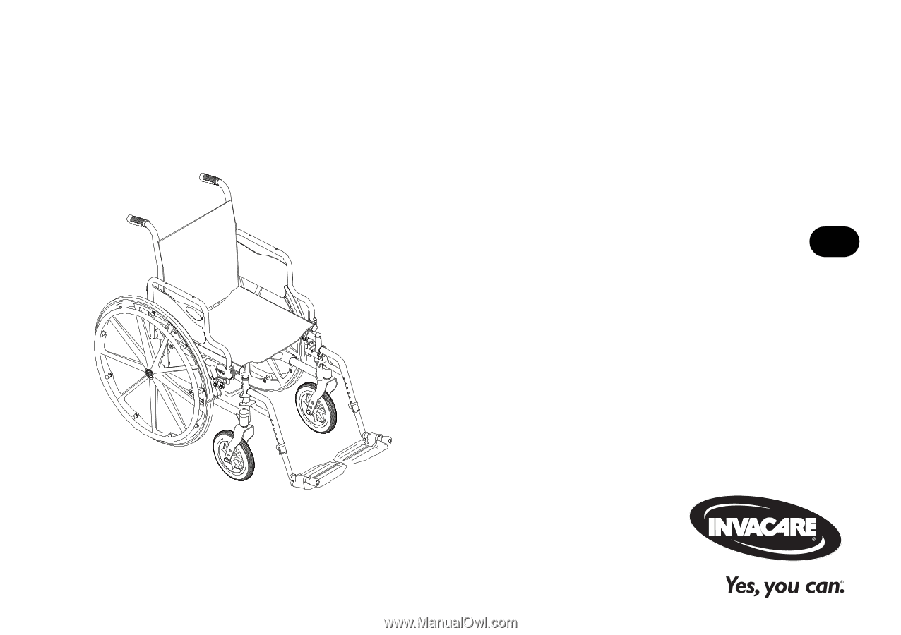
User Manual
This manual MUST be given to the user of the product.
BEFORE using this product, read this manual and save for future reference.
EN
Invacare
®
Tracer
®
SX5
Wheelchair