Invacare 9SL_PTO_41224 Owners Manual
Invacare 9SL_PTO_41224 Manual
 |
View all Invacare 9SL_PTO_41224 manuals
Add to My Manuals
Save this manual to your list of manuals |
Invacare 9SL_PTO_41224 manual content summary:
- Invacare 9SL_PTO_41224 | Owners Manual - Page 1
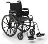
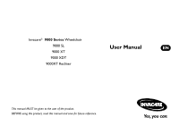
Invacare® 9000 Series Wheelchair 9000 SL 9000 XT 9000 XDT 9000XT Recliner User Manual EN This manual MUST be given to the user of the product. BEFORE using this product, read this manual and save for future reference. - Invacare 9SL_PTO_41224 | Owners Manual - Page 2
are owned by or licensed to Invacare Corporation or its subsidiaries unless otherwise noted. 3-in-1 oil is a registered trademark of American Home Products Corporation. Teflon is a registered trademark of E.I. Du Pont De Nemours and Company. Invacare® 9000 Series Wheelchair 2 Part No. 1056953 - Invacare 9SL_PTO_41224 | Owners Manual - Page 3
...32 Troubleshooting...35 Maintenance ...36 5 FRONT RIGGINGS ...39 Installing/Removing Front Riggings...39 Adjusting Footplate Height ...41 Raising/Lowering Elevating Legrest Assembly ...43 Installing Impact Guards/Calf Strap...44 Replacing Heel Loop ...44 Part No. 1056953 3 Invacare® 9000 - Invacare 9SL_PTO_41224 | Owners Manual - Page 4
Mounting...61 10 ANTI-TIPPERS/WHEEL LOCKS ...62 Installing/Adjusting Anti-tippers...62 Using/Adjusting Disk Wheel Locks...65 Installing Wheel Lock Shoe Extensions ...69 Invacare® 9000 Series Wheelchair 4 Part No. 1056953 - Invacare 9SL_PTO_41224 | Owners Manual - Page 5
...83 Installing/Cleaning Telescoping I.V. Rod/O2 Holders...83 Installing Crutch and Cane Carrier...85 Installing Amputee Bracket...86 Installing the Wheel Lock Extension Handle...91 Part No. 1056953 5 Invacare® 9000 Series Wheelchair - Invacare 9SL_PTO_41224 | Owners Manual - Page 6
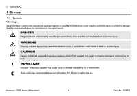
1 General 1.1 Symbols Warnings Signal words are used in this manual and apply to hazards or unsafe practices which could result in personal it is not avoided. Gives useful tips, recommendations and information for efficient, trouble-free use. Invacare® 9000 Series Wheelchair 6 Part No. 1056953 - Invacare 9SL_PTO_41224 | Owners Manual - Page 7
any labor or shipping charges incurred in replacement part installation or repair of any such product. Invacare's sole obligation and your exclusive remedy under this warranty shall be limited to such repair and/or replacement. For warranty service, please contact the dealer from whom you purchased - Invacare 9SL_PTO_41224 | Owners Manual - Page 8
2 OVERVIEW 2 Overview 2.1 Label Locations Serial Number Label is located on the cross brace on the left side of the chair Crossmember Lower Frame Tube 9000 XDT Only Invacare® 9000 Series Wheelchair 8 Part No. 1056953 - Invacare 9SL_PTO_41224 | Owners Manual - Page 9
to the Owner's Manual for proper anti-tipper FULLY RELEASED. KEEP DETENT BALLS CLEAN. 1001948 Part No. 1056953 2 OVERVIEW 9000 XT Recliner Models SERVICE OF SPRING LIFT MECHANISM TO BE PERFORMED BY PROPERLY TRAINED AUTHORIZED SERVICE PERSONNEL ONLY. 1022642 9 Invacare® 9000 Series Wheelchair - Invacare 9SL_PTO_41224 | Owners Manual - Page 10
lbs (114 kg) 43 lbs (16x16 inch seat frame with complete pkg) 20, 22 and 24*-inch composite; Urethane*, pneumatic or pneumatic-flat free insert Invacare® 9000 Series Wheelchair 10 Part No. 1056953 - Invacare 9SL_PTO_41224 | Owners Manual - Page 11
41½ lbs (16 x 16 inch seat frame with complete package) 31 lbs (18 x 16 inch seat) 250 lbs (114 kg) Toggle lock -push or pull Part No. 1056953 11 Invacare® 9000 Series Wheelchair - Invacare 9SL_PTO_41224 | Owners Manual - Page 12
, light vinyl, nylon, sail cloth 250 lbs (114 kg) 50½ lbs 60½ lbs 18x17-inch seat frame with complete package Toggle lock - push or pull Invacare® 9000 Series Wheelchair 12 Part No. 1056953 - Invacare 9SL_PTO_41224 | Owners Manual - Page 13
free insert Permanent Black nylon, black sail cloth, heavy vinyl 46½ lbs 16x16-inch seat frame with complete package 36½ lbs 350 lbs (154 kg) Part No. 1056953 13 Invacare® 9000 Series Wheelchair - Invacare 9SL_PTO_41224 | Owners Manual - Page 14
are based on urethane tires. If wheelchair is equipped with pneumatic (properly inflated) based on urethane tires. If wheelchair is equipped with pneumatic (properly inflated free inserts. If wheelchair is equipped with urethane with flat free inserts. If wheelchair is equipped with urethane tires - Invacare 9SL_PTO_41224 | Owners Manual - Page 15
instructions and any additional instructional material such as owner's manuals, service manuals or instruction parts for shipping damage and test before using. In case of damage, DO NOT use. Contact Invacare/Carrier for further instruction. Part No. 1056953 15 Invacare® 9000 Series Wheelchair - Invacare 9SL_PTO_41224 | Owners Manual - Page 16
or on gravel surfaces, anti tippers may not provide the same level of protection against tipover. Extra caution MUST be observed when traversing such surfaces. Invacare® 9000 Series Wheelchair 16 Part No. 1056953 - Invacare 9SL_PTO_41224 | Owners Manual - Page 17
wheelchair from being folded when left unoccupied in a public place. DO NOT operate on roads, streets or highways. DO NOT allow children to play on or operate the wheelchair. DO NOT operate on soft surfaces such as sand, grass, or gravel. Part No. 1056953 17 Invacare® 9000 Series Wheelchair - Invacare 9SL_PTO_41224 | Owners Manual - Page 18
Failure to observe this warning may result in injury to the user or bystanders. If the wheelchair is exposed to extreme temperature (above 100°F or below 32°F), high humidity and/or becomes assistant help you before attempting it alone. Invacare® 9000 Series Wheelchair 18 Part No. 1056953 - Invacare 9SL_PTO_41224 | Owners Manual - Page 19
wheelchair on an incline. DO NOT attempt to stop the wheelchair while on a sloped surface. Repair and Service Information ƽ WARNING Unless otherwise noted, all service and adjustment should be performed while the wheelchair is unoccupied. Part No. 1056953 19 Invacare® 9000 Series Wheelchair - Invacare 9SL_PTO_41224 | Owners Manual - Page 20
positioning strap is an option on this wheelchair (you may order with or without the seat positioning strap), Invacare strongly recommends ordering the seat positioning strap as . These adjustments MUST be performed by a qualified technician. Invacare® 9000 Series Wheelchair 20 Part No. 1056953 - Invacare 9SL_PTO_41224 | Owners Manual - Page 21
X X X N/A X X CASTER POSITION X N/A X N/A N/A X • X X N/A X X WHEEL SIZE X N/A X N/A N/A X X • X N/A X X WHEEL POSITION X N/A X N/A N/A X X X • N/A X X USER CONDITION X X X X X X X X X • N/A N/A SEAT HEIGHT X N/A X X X X X X X N/A X X Part No. 1056953 21 Invacare® 9000 Series Wheelchair - Invacare 9SL_PTO_41224 | Owners Manual - Page 22
is listed on the side wall of the tire. Weight Limitation ƽ WARNING The 9000 SL, 9000 XT, and 9000XT Recliner wheelchairs have a weight limitation of 250 lbs (114 kg). The 9000XDT wheelchair has a weight limitation of 350 lbs (159 kg). Invacare® 9000 Series Wheelchair 22 Part No. 1056953 - Invacare 9SL_PTO_41224 | Owners Manual - Page 23
. It is Invacare's position that users of wheelchairs should be transferred into appropriate seating in vehicles for transportation and use be made of the restraints made available by the auto industry. Invacare cannot and does not recommend any wheelchair transportation systems. Part No. 1056953 - Invacare 9SL_PTO_41224 | Owners Manual - Page 24
only as a basic guide. The techniques that are discussed on the following pages have been used successfully by many. Individual wheelchair users often develop skills to deal with daily living activities that may differ from those described in this manual. Invacare recognizes and encourages each - Invacare 9SL_PTO_41224 | Owners Manual - Page 25
wheelchair and then reversing it in a straight line. Many activities require the wheelchair owner to reach, bend and transfer in and out of the wheelchair wheelchair. wheelchair are reaching as the wheelchair may tip over. cause the wheelchair to tip over. Backwards Position wheelchair as close as - Invacare 9SL_PTO_41224 | Owners Manual - Page 26
Roll the wheelchair forward and slowly lower the front of the wheelchair in one continuous movement onto the sidewalk. Push the wheelchair forward until the rear wheels roll up and over the curb. Step Tube FIGURE 2 Method 1 - Wheelchair With Step Tubes Invacare® 9000 Series Wheelchair 26 Part No - Invacare 9SL_PTO_41224 | Owners Manual - Page 27
recommends that, if possible, the user be removed from the wheelchair prior to moving. Invacare recommends using two assistants and making thorough preparations. Make sure to use only secure, non-detachable parts for hand-held supports. 9000 XT recliner only - ALWAYS return the back to the upright - Invacare 9SL_PTO_41224 | Owners Manual - Page 28
process. 5. The wheelchair should not be lowered until the last stair has been negotiated and the wheelchair has been rolled away from the stairway. 6. If necessary, rotate the anti-tippers so the wheels are facing down. FIGURE 4 Stairways Invacare® 9000 Series Wheelchair 28 Part No. 1056953 - Invacare 9SL_PTO_41224 | Owners Manual - Page 29
To and From Other Seats ƽ WARNING Before attempting to transfer in or out of the wheelchair, every precaution should be taken to reduce the gap distance. Turn both casters parallel to possible. FIGURE 5 Transferring To and From Other Seats Part No. 1056953 29 Invacare® 9000 Series Wheelchair - Invacare 9SL_PTO_41224 | Owners Manual - Page 30
Bar on page 75. 6. Engage both wheel locks, open the footrest/legrest for clearance and transfer into the wheelchair. Refer to Transferring To and From Other Seats on page 29. Press DOWN on Seat Rail FIGURE 6 Unfolding and Folding Wheelchair Invacare® 9000 Series Wheelchair 30 Part No. 1056953 - Invacare 9SL_PTO_41224 | Owners Manual - Page 31
of the wheelchair. 3. Pivot close the wheelchair by grasping wheelchair. 3. Pivot footplates upward to vertical position. 4. From behind the wheelchair wheelchair begins to close. 7. Continue to close the wheelchair by grasping the armrest furthest from you and pulling the armrest towards you. Part - Invacare 9SL_PTO_41224 | Owners Manual - Page 32
SAFETY INSPECTION/TROUBLESHOOTING 4 Safety Inspection/troubleshooting Every six months or as necessary, take your wheelchair to a qualified technician for a thorough inspection and servicing. Regular cleaning will reveal loose or worn parts and enhance the smooth operation of your wheelchair. To - Invacare 9SL_PTO_41224 | Owners Manual - Page 33
4 SAFETY INSPECTION/TROUBLESHOOTING ƽ CAUTION As with any vehicle, check the wheels and tires periodically for cracks and wear. Replace caster. Caster should come to a gradual stop. ❑ Inspect front caster for cracked, bent or broken spokes. Part No. 1056953 33 Invacare® 9000 Series Wheelchair - Invacare 9SL_PTO_41224 | Owners Manual - Page 34
4 SAFETY INSPECTION/TROUBLESHOOTING Inspect/Adjust Monthly ❑ Ensure that the wheelchair rolls straight (no excessive drag or pull to one side). ❑ Check that and armrests. ❑ Check that all labels are present and legible. Replace if necessary. Invacare® 9000 Series Wheelchair 34 Part No. 1056953 - Invacare 9SL_PTO_41224 | Owners Manual - Page 35
Veers Right/Left Chair 3 Wheels X X X X X X 4 SAFETY INSPECTION/TROUBLESHOOTING Sluggish Turn Casters Squeaks Looseness in or Performance Flutter and Rattles Chair Solutions X X rear wheels are equally spaced away from seat frame. Part No. 1056953 35 Invacare® 9000 Series Wheelchair - Invacare 9SL_PTO_41224 | Owners Manual - Page 36
4 SAFETY INSPECTION/TROUBLESHOOTING 4.3 Maintenance Maintenance Safety Precautions ƽ WARNING After any adjustments, repair or service and before use, make sure all attaching hardware is tightened is listed on the sidewall of the tire. Invacare® 9000 Series Wheelchair 36 Part No. 1056953 - Invacare 9SL_PTO_41224 | Owners Manual - Page 37
4 SAFETY INSPECTION/TROUBLESHOOTING ƽ CAUTION As with any vehicle, check the wheels and tires periodically for cracks and wear. monthly for wear/looseness/deterioration. Clean if desired. Replace if looseness or deterioration is found. Part No. 1056953 37 Invacare® 9000 Series Wheelchair - Invacare 9SL_PTO_41224 | Owners Manual - Page 38
tires is not recommended. If the solid urethane or semi-pneumatic tires need replaced, Invacare recommends replacing complete caster assembly. For pneumatic tires, replacement of the tire or tube must be performed by a qualified technician. Invacare® 9000 Series Wheelchair 38 Part No. 1056953 - Invacare 9SL_PTO_41224 | Owners Manual - Page 39
outward. Removing 1. Push the front rigging release lever inward. 2. Rotate swingaway front rigging assembly outward. 3. Lift the swingaway front rigging assembly off the hinge pins. Part No. 1056953 39 Invacare® 9000 Series Wheelchair - Invacare 9SL_PTO_41224 | Owners Manual - Page 40
5 FRONT RIGGINGS Hinge Pins Swingaway footrest shown. Front Rigging Release Lever Front Rigging Assembly Hinge Plates Footplate FIGURE 1 Installing/Removing Front Riggings Invacare® 9000 Series Wheelchair 40 Part No. 1056953 - Invacare 9SL_PTO_41224 | Owners Manual - Page 41
Ensure that the release buttons fully protrude from holes on both sides of the front rigging support. Swingaway footrest shown. 5. Rotate cam lock lever down to locked position. 6. . Refer to Installing/Removing Front Riggings on page 39. Part No. 1056953 41 Invacare® 9000 Series Wheelchair - Invacare 9SL_PTO_41224 | Owners Manual - Page 42
of the swingaway front rigging, insert the threaded rivet through both the front rigging support and the footplate assembly. 7. From the inside of the swingaway front rigging, position. 10. Repeat STEPS 1-9 to adjust the remaining footrest. Invacare® 9000 Series Wheelchair 42 Part No. 1056953 - Invacare 9SL_PTO_41224 | Owners Manual - Page 43
the following: A. Support user leg with one hand. B. Push release lever downward with other hand. C. Gently, lower user leg down and rest against the legrest. Release Lever Support Tube FIGURE 4 Raising/Lowering Elevating Legrest Assembly Part No. 1056953 43 Invacare® 9000 Series Wheelchair - Invacare 9SL_PTO_41224 | Owners Manual - Page 44
the threaded rivet and button head screw securing the footplate assembly to the front rigging support. 3. Remove the mounting screw, spacer and locknut that secure the heel loop to the footplate. 4. Remove existing heel loop from slide tube. Invacare® 9000 Series Wheelchair 44 Part No. 1056953 - Invacare 9SL_PTO_41224 | Owners Manual - Page 45
Ensure that the release buttons fully protrude from holes on both sides of the upper footrest support. • Bolt-In-Place Footplates: i. From the outside of the swingaway front rigging, Spacer Locknut Slide Tube Footplate Assembly Footplate Part No. 1056953 45 Invacare® 9000 Series Wheelchair - Invacare 9SL_PTO_41224 | Owners Manual - Page 46
) position when the desired armrest height is achieved. 4. Repeat STEPS 1-3 for other armrest. Armrest Locked (Vertical) Height Adjustment Lever Unlocked (Horizontal) FIGURE 1 Adjusting Armrest Height Invacare® 9000 Series Wheelchair 46 Part No. 1056953 - Invacare 9SL_PTO_41224 | Owners Manual - Page 47
position when placing armrest into the arm sockets. 4. Lock the swing-back arms by rotating the armrest release lever towards the inside of the wheelchair. Swing Back Arm Front Armrest Release Lever Rear Arm Socket FIGURE 2 Using Swing-Back Arms Part No. 1056953 47 Invacare® 9000 Series - Invacare 9SL_PTO_41224 | Owners Manual - Page 48
of the wheelchair. 2. Lock the armrest by turning the armrest release levers towards the inside of the wheelchair. Rear Arm Post Armrest Release Lever Arm Socket Armrest Armrest Release Lever Arm Socket FIGURE 3 Removing or Replacing Armrest Invacare® 9000 Series Wheelchair 48 Part No. 1056953 - Invacare 9SL_PTO_41224 | Owners Manual - Page 49
of frame. B. For space saver arms - position arm socket on inside of frame. Make sure arm sockets sit flush against the wheelchair frame. 5. Reinstall the hex screw and locknut that secure the arm socket to the wheelchair frame and securely tighten. Part No. 1056953 49 Invacare® 9000 Series - Invacare 9SL_PTO_41224 | Owners Manual - Page 50
Arm Socket (Outside of Wheelchair Frame) Conventional Arm Position Locknut Locknut Hex Screw Left Side of Wheelchair Frame Wheelchair Frame Right Side of Wheelchair Frame FIGURE 5 Converting Between Space Saver and Conventional Arms Invacare® 9000 Series Wheelchair 50 Part No. 1056953 - Invacare 9SL_PTO_41224 | Owners Manual - Page 51
WARNING After any adjustments, repair or service and before use, make sure all attaching wheelchair frame. 3. Install new seat upholstery by reversing STEPS 1-2. Mounting Screws 16-inch Seat Depth Part No. 1056953 Seat Upholstery Wheelchair Frame FIGURE 1 Replacing Seat Upholstery 51 Invacare - Invacare 9SL_PTO_41224 | Owners Manual - Page 52
the back canes. 3. Cut the tie wraps that secure the existing back upholstery to the wheelchair frame. 4. Securely tighten the new back upholstery to the back canes with the six mounting existing back upholstery to the back canes (Detail "A"). Invacare® 9000 Series Wheelchair 52 Part No. 1056953 - Invacare 9SL_PTO_41224 | Owners Manual - Page 53
canes with the existing mounting screws and washers. DETAIL "A" Back Upholstery DETAIL "B" Washer Mounting Screws Back Cane Back Cane Spacers Mounting Screws Wheelchair Frame Locknuts Part No. 1056953 FIGURE 8 Replacing Back Upholstery - Slip-On Back Upholstery 53 Invacare® 9000 Series - Invacare 9SL_PTO_41224 | Owners Manual - Page 54
the wheelchair to decrease in stability. These adjustments must be performed by a qualified technician. 7.4 Adjusting Seat Width ƽ WARNING Adjusting the seat width of the 9000SL, 9000XT, 9000XDT MUST be performed by a qualified technician. Invacare® 9000 Series Wheelchair 54 Part No. 1056953 - Invacare 9SL_PTO_41224 | Owners Manual - Page 55
WHEELS ƽ WARNING After any adjustments, repair or service and before use, make sure all attaching hardware is wheelchairs. If replacing the same size rear wheel, note the mounting position on the wheelchair frame for proper reinstallation of the new rear wheel. Part No. 1056953 55 Invacare - Invacare 9SL_PTO_41224 | Owners Manual - Page 56
lock (Detail "A"). Keep detent balls clean. Invacare recommends inserting quick-release axles with the detent pin to the inside of the wheelchair to prevent accidental release during contact activities. Adjusting Quick-Release Axle on page 58. Invacare® 9000 Series Wheelchair 56 Part No. 1056953 - Invacare 9SL_PTO_41224 | Owners Manual - Page 57
77. 2. Remove the mounting screws that secure the handrim to rear wheel. 3. Remove the existing handrim. 4. Install the new handrim by reversing the preceding steps. Part No. 1056953 57 Rear Wheel Mounting Screw Handrim FIGURE 2 Replacing Rear Wheel Handrim Invacare® 9000 Series Wheelchair - Invacare 9SL_PTO_41224 | Owners Manual - Page 58
Make sure detent pin and detent balls of the quick-release axles are fully released before operating the wheelchair. Keep detent balls clean. 5. Reinstall rear wheel onto the wheelchair. Refer to Removing/Installing Rear Wheels on page 55. Invacare® 9000 Series Wheelchair 58 Part No. 1056953 - Invacare 9SL_PTO_41224 | Owners Manual - Page 59
Detent Balls Axle Bushing Locknut Detent Pin Axle Spacer (Conventional Arms Only) Rear Wheel Hub Quick-Release Axle FIGURE 3 Adjusting Quick-Release Axle 8 REAR WHEELS Part No. 1056953 59 Invacare® 9000 Series Wheelchair - Invacare 9SL_PTO_41224 | Owners Manual - Page 60
FRONT CASTERS 9 Front Casters ƽ WARNING After any adjustments, repair or service and before use, make sure all attaching hardware is tightened securely. . 5. Reassemble by reversing STEPS 1-3. 6. Repeat STEPS 1-5 for the opposite front caster. Invacare® 9000 Series Wheelchair 60 Part No. 1056953 - Invacare 9SL_PTO_41224 | Owners Manual - Page 61
downward position). D. Adjust locknuts according to freedom of caster swing. 8. Test wheelchair for maneuverability. 9. Readjust locknuts if necessary, and repeat STEPS 7-8 until correct MUST be performed by a qualified technician. Part No. 1056953 61 Invacare® 9000 Series Wheelchair - Invacare 9SL_PTO_41224 | Owners Manual - Page 62
ƽ WARNING After any adjustments, repair or service and before use, make sure all attaching this section of the manual for correct usage and adjustment. If these requirements cannot be achieved, DO NOT use the wheelchair. Contact a qualified Invacare® 9000 Series Wheelchair 62 Part No. 1056953 - Invacare 9SL_PTO_41224 | Owners Manual - Page 63
the release buttons are fully engaged in adjustment holes. DETAIL "A" Release Buttons Anti-Tipper Height DETAIL "B" 1½ inches 2 inches FIGURE 2 Adjusting Anti-Tippers Anti-Tipper Length Part No. 1056953 63 Invacare® 9000 Series Wheelchair - Invacare 9SL_PTO_41224 | Owners Manual - Page 64
to the following charts to ensure the correct anti-tipper is installed in the wheelchair. Seat-to-Floor heights are approximate depending on front caster size and type. ½ / 3½-inches N/A 1058366 15½-inches 11-5/8 / 2-3/4-inches N/A 1058752 Invacare® 9000 Series Wheelchair 64 Part No. 1056953 - Invacare 9SL_PTO_41224 | Owners Manual - Page 65
engaging the wheel locks. 2. Depending on the model of wheel lock installed on the wheelchair, perform one of the following: • Push-to-Lock - To engage, push the wheel lock handle forward. • Pull-to-Lock - To engage, pull the wheel lock handle backward. Part No. 1056953 65 Invacare® 9000 Series - Invacare 9SL_PTO_41224 | Owners Manual - Page 66
, the wheel lock shoe embeds the tire 1/8-inch (3/16-inch for pneumatic tires) and holds the occupied wheelchair in place when pushed. 4. Securely tighten the bolt and locknut or socket screws securing the wheel lock to the wheelchair frame. Invacare® 9000 Series Wheelchair 66 Part No. 1056953 - Invacare 9SL_PTO_41224 | Owners Manual - Page 67
wheel lock. 11. Engage both wheel locks and ensure the occupied wheelchair is held in place when pushed. ƽ WARNING If wheel locks DO NOT hold the occupied wheelchair in place, contact a qualified technician. Otherwise injury or damage may occur. Part No. 1056953 67 Invacare® 9000 Series - Invacare 9SL_PTO_41224 | Owners Manual - Page 68
Locknut Wheel Lock Handle Wheel Lock Wheel Lock Clamp Rear Wheel Wheel Lock Shoe Wheel Lock Shoe Rear Wheel FIGURE 4 Adjusting Patient-Operated Wheel Locks Invacare® 9000 Series Wheelchair 68 Part No. 1056953 - Invacare 9SL_PTO_41224 | Owners Manual - Page 69
to the wheel lock shoes. Wheel Lock Shoe Extension Set Screws Pointed End of Wheel Lock Shoe Extension Slot FIGURE 5 Installing Wheel Lock Shoe Extensions Part No. 1056953 69 Invacare® 9000 Series Wheelchair - Invacare 9SL_PTO_41224 | Owners Manual - Page 70
service and before use, make sure all attaching hardware is tightened securely. Otherwise injury or damage may occur. 11.1 Operating Recliner ƽ WARNING ALWAYS make sure that the wheelchair ) or seek assistance if necessary to avoid injury. Invacare® 9000 Series Wheelchair 70 Part No. 1056953 - Invacare 9SL_PTO_41224 | Owners Manual - Page 71
service and before use, make sure all attaching hardware is tightened securely. Otherwise injury or damage may occur. LIft kit models only - DO NOT attempt to recline or incline the wheelchair STEPS 8-11 keeping in mind proper body mechanics. Part No. 1056953 71 Invacare® 9000 Series Wheelchair - Invacare 9SL_PTO_41224 | Owners Manual - Page 72
from behind headrest upholstery. 2. Secure straps of the new headrest pillow onto fastening strips located on back of headrest upholstery. Fastening Strips Headrest Upholstery Strap Invacare® 9000 Series Wheelchair Strap Headrest Pillow FIGURE 2 Replacing Headrest Pillow 72 Part No. 1056953 - Invacare 9SL_PTO_41224 | Owners Manual - Page 73
To remove and install the bottom two mounting screws of the back upholstery, the wheelchair MUST be partially folded. 3. Remove the twelve mounting screws that secure the back Mounting Screws Part No. 1056953 FIGURE 3 Replacing Headrest/Back Upholstery 73 Invacare® 9000 Series Wheelchair - Invacare 9SL_PTO_41224 | Owners Manual - Page 74
MUST be performed by a qualified technician. 11.4 Adjusting Seat Width ƽ WARNING Adjusting the seat width of the 9000XT Recliner MUST be performed by a qualified technician. Invacare® 9000 Series Wheelchair 74 Part No. 1056953 - Invacare 9SL_PTO_41224 | Owners Manual - Page 75
bar to the side frames. 2. Remove existing spreader bar. 3. Secure new spreader bar to the side frames with the existing locking knobs. Securely tighten. Part No. 1056953 75 Locking Knobs Spreader Bar Side Frame Side Frame FIGURE 6 Replacing Spreader Bar Invacare® 9000 Series Wheelchair - Invacare 9SL_PTO_41224 | Owners Manual - Page 76
7 and the following chart to ensure the correct anti-tipper is installed in the wheelchair. Seat-to-floor heights are approximate depending on front caster type. The anti-tipper height "B" Anti-Tipper Length FIGURE 7 Installing Anti-Tippers Invacare® 9000 Series Wheelchair 76 Part No. 1056953 - Invacare 9SL_PTO_41224 | Owners Manual - Page 77
and rear wheel to the wheelchair frame. 2. Secure rear wheel, patient operated wheel lock, and spacers to wheelchair frame with axle mounting screw and Locks on page 66. Locknut Wheelchair Frame Spacers Rear Wheel Patient Operated Wheel Lock Axle Mounting Screw Part No. 1056953 FIGURE 8 - Invacare 9SL_PTO_41224 | Owners Manual - Page 78
wheelchair frame. 2. Remove rear wheel from side frame. 3. Secure rear wheel and spacer to wheelchair page 79. Axle Mounting Screw Wheelchair Frame Locknut Spacer Rear Wheel FIGURE Locks ƽ WARNING DO NOT attempt to stop a moving wheelchair with wheel locks. Wheel locks are not brakes. 1. - Invacare 9SL_PTO_41224 | Owners Manual - Page 79
the wheelchair. 5. Repeat the above procedures until the wheel lock holds the wheelchair. 6. Repeat STEPS 1-5 for the opposite wheel lock. Ensure the wheel lock shoe completely covers the tire contact area. See Detail "A" for proper positioning of wheel lock shoe. Part No. 1056953 79 Invacare - Invacare 9SL_PTO_41224 | Owners Manual - Page 80
Tire Contact Area Bolt and Locknut Wheel Lock Handle Tire Section Recliner Tube Wheel Lock Shoe Rear Wheel FIGURE 11 Adjusting Attendant Operated Wheel Locks Invacare® 9000 Series Wheelchair 80 Part No. 1056953 - Invacare 9SL_PTO_41224 | Owners Manual - Page 81
11 RECLINER Hex Screw Outside of Wheelchair Frame DETAIL "B" Locknut (STEP 6) Back Tube (STEP 3) I.V. Holder (STEP 4) Clevis Bracket (STEP 3) Mounting Screw (STEP 6) Pivot Screw (STEP 4) Locknut (STEPS 3 and 5) FIGURE 12 Installing I.V. Holder Part No. 1056953 81 Invacare® 9000 Series - Invacare 9SL_PTO_41224 | Owners Manual - Page 82
Wheelchair 82 Attaching hardware enlarged 3X scale for clarity. Locknut Steel Washer Small Nylon Washer Large Nylon Washer Rear Cylinder Mounting Screw I.V. Rod Adjustment Knob I.V. Rod Support Tube I.V. Rod Holder FIGURE 13 Installing I.V. Rod Support Tube - Adjusting I.V. Rod Part - Invacare 9SL_PTO_41224 | Owners Manual - Page 83
positions on wheelchair frame. 2. Secure telescoping I.V. rod/O2 holder to the wheelchair frame with hex screw, spacer and locknut. 3. Telescoping I.V. Rod Holder Only - Secure the top of the telescoping I.V. rod holder to the wheelchair frame with a tie wrap. Part No. 1056953 83 Invacare® 9000 - Invacare 9SL_PTO_41224 | Owners Manual - Page 84
MUST be removed from the wheelchair when cleaning the O2 holder. Otherwise, injury or damage may occur if cleaning agents come in contact with the O2 regulator. 1. Remove the user, any I.V. medication and the O2 cylinder from the wheelchair. Invacare® 9000 Series Wheelchair 84 Part No. 1056953 - Invacare 9SL_PTO_41224 | Owners Manual - Page 85
re-occupy the wheelchair. 12 OPTIONS 12 with folding the wheelchair, the rear wheelchair. Ensure the base is towards the inside of the wheelchair wheelchair. 3. Securely tighten the locknut that secures the base to the step tube of the wheelchair the strap to the wheelchair. 7. The base cleans - Invacare 9SL_PTO_41224 | Owners Manual - Page 86
B HEMI B HEMI A AXLE SPACER POSITION (ON BRACKET) DOWN DOWN UP UP SIDE OF WHEELCHAIR RIGHT LEFT RIGHT LEFT * "A" and "B" are stamped on the sides of the amputee bracket. AXLE MOUNTING POSITION (ON WHEELCHAIR) TOP TOP BOTTOM BOTTOM Invacare® 9000 Series Wheelchair 86 Part No. 1056953 - Invacare 9SL_PTO_41224 | Owners Manual - Page 87
pointing towards the outside of the wheelchair. 3. Install the two hex screws and locknuts that secure the amputee bracket to the wheelchair. 4. Install the rear wheels onto the wheelchair. Refer to Removing/Installing Rear Wheels on page 55. 12 OPTIONS Part No. 1056953 87 Invacare® 9000 Series - Invacare 9SL_PTO_41224 | Owners Manual - Page 88
"A" Locknuts Bracket "B" Adult Right Axle Spacer Toward Outside of Wheelchair Left Right Rear View of Amputee Bracket Adult Left Axle Spacer Toward Outside of Wheelchair Hex Screws Hemi Left Invacare® 9000 Series Wheelchair FIGURE 4 Installing Amputee Bracket - 9000SL/XT 88 Hemi Right - Invacare 9SL_PTO_41224 | Owners Manual - Page 89
spacer is pointing towards the outside of the wheelchair. 3. Install the two hex screws and locknuts that secure the amputee bracket to the wheelchair. 4. Install the rear wheels onto the wheelchair. Refer to Removing/Installing Rear Wheels on page 55. Part No. 1056953 89 Invacare® 9000 Series - Invacare 9SL_PTO_41224 | Owners Manual - Page 90
Bracket "A" Hemi Left Left Adult Left Hemi Right Right Adult Right Bracket "B" Axle Spacer Toward Outside of Wheelchair Rear View of Amputee Bracket Hex Screws Tall Right Tall Left Locknuts Invacare® 9000 Series Wheelchair FIGURE 5 Installing Amputee Bracket - 9000XDT 90 Part No. 1056953 - Invacare 9SL_PTO_41224 | Owners Manual - Page 91
the extension handle over the wheel lock handle (Detail "B"). Detail "A" Rubber Tip Detail "B" Wheel Lock Extension Handle Wheel Lock Handle Wheel Lock Handle Wheel Lock Part No. 1056953 Wheel Lock FIGURE 6 Installing the Wheel Lock Extension Handle 91 Invacare® 9000 Series Wheelchair - Invacare 9SL_PTO_41224 | Owners Manual - Page 92
Part No. 1056953 Rev P- 11/10 Invacare Corporation USA One Invacare Way Elyria, Ohio USA 44036-2125 800-333-6900 Canada 570 Matheson Blvd E Unit 8 Mississauga Ontario L4Z 4G4 Canada 800-668-5324 www.invacare.com
-
 1
1 -
 2
2 -
 3
3 -
 4
4 -
 5
5 -
 6
6 -
 7
7 -
8
-
9
-
10
-
11
-
12
-
13
-
14
-
15
-
16
-
17
-
18
-
19
-
20
-
21
-
22
-
23
-
24
-
25
-
26
-
27
-
28
-
29
-
30
-
31
-
32
-
33
-
34
-
35
-
36
-
37
-
38
-
39
-
40
-
41
-
42
-
43
-
44
-
45
-
46
-
47
-
48
-
49
-
50
-
51
-
52
-
53
-
54
-
55
-
56
-
57
-
58
-
59
-
60
-
61
-
62
-
63
-
64
-
65
-
66
-
67
-
68
-
69
-
70
-
71
-
72
-
73
-
74
-
75
-
76
-
77
-
78
-
79
-
80
-
81
-
82
-
83
-
84
-
85
-
86
-
87
-
88
-
89
-
90
-
91
-
92
 |
 |

User Manual
This manual MUST be given to the user of the product.
BEFORE using this product, read this manual and save for future reference.
EN
Invacare®
9000 Series
Wheelchair
9000 SL
9000 XT
9000 XDT
9000XT Recliner