Invacare GHS350 Owners Manual
Invacare GHS350 Manual
 |
View all Invacare GHS350 manuals
Add to My Manuals
Save this manual to your list of manuals |
Invacare GHS350 manual content summary:
- Invacare GHS350 | Owners Manual - Page 1
Owner's Operator and Maintenance Manual Get-U-Up™ Lift DEALER: This manual MUST be given to the user of the patient lift. USER: BEFORE using this patient lift, read this manual and save for future reference. For more information regarding Invacare products, parts, and services, please visit www. - Invacare GHS350 | Owners Manual - Page 2
READING AND UNDERSTANDING THESE INSTRUCTIONS AND ANY ADDITIONAL INSTRUCTIONAL MATERIAL SUCH AS OWNER'S MANUALS, SERVICE MANUALS OR INSTRUCTION SHEETS SUPPLIED WITH THIS PRODUCT DOWN on Boom. NOTE: Updated versions of this manual are available on www.invacare.com. Get-U-Up™ Lift 2 Part No 1148115 - Invacare GHS350 | Owners Manual - Page 3
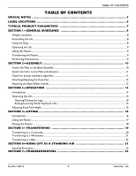
16 Lifting the Patient ...17 Moving the Patient ...18 SECTION 5-TRANSFERRING 19 Transferring to a Commode...20 Transferring to a Wheelchair...21 Transferring to a Bed ...22 SECTION 6-USING LIFT AS A STANDING AID 23 Standing Procedure...23 SECTION 7-TROUBLESHOOTING 24 Part No 1148115 3 Get-U-Up - Invacare GHS350 | Owners Manual - Page 4
CONTENTS TABLE OF CONTENTS SECTION 8-MAINTENANCE 25 Maintenance Safety Inspection Checklist...25 Hydraulic Pump...25 Lubricating the Lift ...26 Detecting Wear and Damage...26 Cleaning the Sling and the Lift...26 Replacing the Knee Pad ...26 LIMITED WARRANTY 27 Get-U-Up™ Lift 4 Part No 1148115 - Invacare GHS350 | Owners Manual - Page 5
Signal words are used in this manual and apply to hazards or unsafe parts for shipping damage. If shipping damage is noted, DO NOT use. Contact dealer/carrier for further instruction. MAINTENANCE Maintenance MUST be performed ONLY by qualified personnel. Part No 1148115 5 Get-U-Up™ Lift - Invacare GHS350 | Owners Manual - Page 6
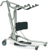
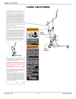
The mast (C) includes the steering handles used to move and guide the lift. The mast is supported in a socket in the rear center of the base with casters (A). For transporting the lift in a vehicle, the mast, boom and pump assembly may be lifted from the base socket for convenient storage. Each time - Invacare GHS350 | Owners Manual - Page 7
WIDTH CASTER SIZE (REAR/FRONT) SLING OPTIONS SLING MATERIAL STANDING SLING WIDTH LENGTH TRANSPORT SLING WIDTH LENGTH WEIGHT CAPACITY WEIGHT IN 5 inches / 3 inches Standing or Transport Polyester 36 inches 13 inches 38.5 inches 36 inches 350 lbs 100 lbs 88 lbs Part No 1148115 7 Get-U-Up™ Lift - Invacare GHS350 | Owners Manual - Page 8
read the instructions in this Owner's Manual, observe a trained team of experts performing the lifting procedures and then perform the entire lift procedure several times with proper supervision and a capable individual acting as a patient. Invacare Stand Assist and Transfer slings are specifically - Invacare GHS350 | Owners Manual - Page 9
the steering handle on the mast at ALL times to push or pull the patient lift. Invacare recommends locking the rear swivel casters ONLY when positioning or removing the sling (stand assist or transfer) from around the patient. Transferring the Patient Before transferring, check that the product - Invacare GHS350 | Owners Manual - Page 10
and tighten securely. Side view of the Base Assembly and Mast Notch Locking Screw Mast Socket Tab FIGURE 2.1 Attach the Mast to the Base Assembly Get-U-Up™ Lift 10 Part No 1148115 - Invacare GHS350 | Owners Manual - Page 11
the pump assembly problems continue, contact the Technical Support Department at Invacare. Horn Mounting Lug (1 of 2) Locknut and Steel Washer Cylinder Lugs Horn Locknut Actuator Cylinder Rod Shoulder Bolt Part No 1148115 FIGURE 2.2 Attach the Horn to the Mast and Actuator 11 Get-U-Up™ Lift - Invacare GHS350 | Owners Manual - Page 12
FIGURE 2.3. ƽ WARNING Never adjust knee pad while patient is in the standing position or while the lift is moving. Always make sure that the adjustment pins are fully engaged removed. Thumbscrew Base Shifter Handle Get-U-Up™ Lift Cam Lock Assembly FIGURE 2.4 Attaching the Base Shifter Handle 12 - Invacare GHS350 | Owners Manual - Page 13
weight limitation for the Get-U-Up Lift is 350 lbs. ALWAYS keep hands, fingers, feet and toes clear of moving parts to avoid injury. NOTE: Invacare recommends that two assistants be used for all lifting preparation and transferring to/from procedures; however, the stand up lift can be operated with - Invacare GHS350 | Owners Manual - Page 14
locked in place or injury and/or damage may occur. Closing the Legs 1. Stand at the rear of the lift and grasp the shifter handle in one‐hand. 2. Place the opposite hand on Handle Mast Shifter Handle Shifter Handle Mast Get-U-Up™ Lift FIGURE 3.1 Opening/Closing the Legs 14 Part No 1148115 - Invacare GHS350 | Owners Manual - Page 15
is opened. A safety gate is part of the hydraulic system that maintains a SLOW constant descent of the boom regardless of how far the control valve is opened. Pump Handle Pump Handle Closed Control Valve Open FIGURE 3.2 Raising/Lowering the Hydraulic Lift Part No 1148115 15 Get-U-Up™ Lift - Invacare GHS350 | Owners Manual - Page 16
permit proper operation by one assistant. The use of one assistant is based on the evaluation of the health care professional for each individual case. NOTE: Refer to the patient sling owner's manual, P/N 1023891, for more information. Positioning the Stand Up Lift NOTE: Before positioning the legs - Invacare GHS350 | Owners Manual - Page 17
For this procedure, refer to FIGURE 4.1 on page 18. 1. Instruct patient to hold onto the handgrips on both sides of the stand up lift. Refer to Detail "A". 2. Instruct the patient to lean back into the stand assist or transport sling. 3. Ensure the following: • Patient's knees are secure against the - Invacare GHS350 | Owners Manual - Page 18
DO NOT move a person suspended in a sling any distance. The Invacare lift is NOT a transport device. It is intended to transfer a seated individual from one resting surface to another (such as a bed to a wheelchair). Otherwise, injury or damage may occur. The legs of the stand up lift MUST be in the - Invacare GHS350 | Owners Manual - Page 19
to push or pull the lift. Be sure to check the sling attachments each time the sling is removed and replaced to ensure that it is properly attached before the patient is removed from a surface. NOTE: Invacare recommends that two assistants be used for all lifting preparation and transferring to/from - Invacare GHS350 | Owners Manual - Page 20
supported by the lift. Refer to Detail "A". 2. Guide the patient onto the commode chair. 3. Lower the patient onto the commode chair. 4. Perform one of the following (refer to Detail "B" or "C"): • Standing Sling ‐ unhook the standing sling from the attachment points on the lift. • Transport Sling - Invacare GHS350 | Owners Manual - Page 21
for transport. Otherwise, injury may result. 4. Position the patient over the wheelchair. 5. Lower the patient into the wheelchair. Refer to Detail "C". 6. Unhook the sling from all attachment points on the lift. Refer to Detail "D". 7. Instruct patient to lift their feet off the footplate. Assist - Invacare GHS350 | Owners Manual - Page 22
with their weight fully supported by the lift. 2. Lower the patient onto the bed. 3. Unhook the sling from all attachment points on the lift. 4. Instruct the patient to lift their feet off of the footplate. Assist the patient if necessary. 5. Remove the standing or transport sling from around the - Invacare GHS350 | Owners Manual - Page 23
refer to FIGURE 6.1. NOTE: The Get‐U‐Up lift can be used as an aid to lift a person from a seated to a standing position. A minimum of two caregivers is required for this procedure. NOTE: Invacare recommends that two assistants be used for all lifting preparation and transferring to/from procedures - Invacare GHS350 | Owners Manual - Page 24
to Hydraulic Pump on page 25. Lift arms will not lower in uppermost position. Lift arms require a minimum weight load to lower from the uppermost position. Pull down slightly on the lift arms. NOTE: If problems are not remedied by the suggested means, please contact your dealer or Invacare. Get - Invacare GHS350 | Owners Manual - Page 25
, the pump unit MUST be returned to the factory for repair. DO NOT attempt to open the hydraulic pump or obtain local service. This will void the warranty and might result in damage and costly repair. Consult your dealer or contact Invacare for information. Part No 1148115 25 Get-U-Up™ Lift - Invacare GHS350 | Owners Manual - Page 26
Wear and Damage It is important to inspect all stressed parts, such as slings, sling attachment knobs, and any pivot for slings for signs of cracking, fraying, deformation or deterioration. Replace any defective parts immediately and ensure that the lift is not used until repairs are made. All - Invacare GHS350 | Owners Manual - Page 27
for a period of three years on the lift and one year on the hydraulic pump from the date of purchase. If within such warranty period any such product shall be proven to be defective, such product shall be repaired or replaced, at Invacare's option. This warranty does not include any labor - Invacare GHS350 | Owners Manual - Page 28
Ontario L4Z 4G4 Canada 800-668-5324 All rights reserved. Trademarks are identified by the symbols ™ and ®. All trademarks are owned by or licensed to Invacare Corporation or its subsidiaries unless otherwise noted. ©2009 Invacare Corporation Part No 1148115 Rev B - 06/09
-
 1
1 -
 2
2 -
 3
3 -
 4
4 -
 5
5 -
 6
6 -
 7
7 -
8
-
9
-
10
-
11
-
12
-
13
-
14
-
15
-
16
-
17
-
18
-
19
-
20
-
21
-
22
-
23
-
24
-
25
-
26
-
27
-
28
 |
 |
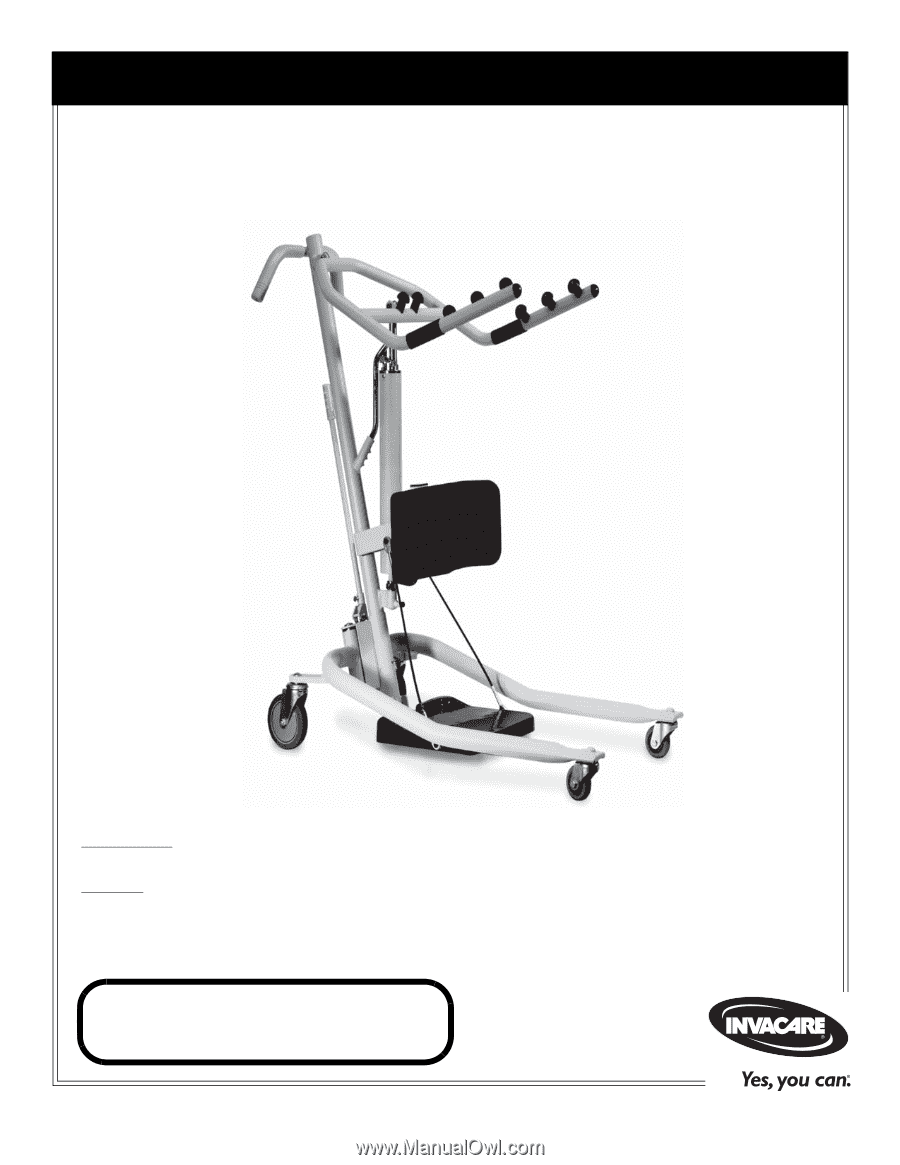
Owner’s Operator and Maintenance Manual
DEALER:
This manual MUST be given to the user of the patient lift.
USER:
BEFORE using this patient lift, read this manual and save for future reference.
For more information regarding
Invacare products,
parts, and services,
please visit www.invacare.com
Get-U-Up
™
Lift