Invacare M51PSR20B Owners Manual
Invacare M51PSR20B Manual
 |
View all Invacare M51PSR20B manuals
Add to My Manuals
Save this manual to your list of manuals |
Invacare M51PSR20B manual content summary:
- Invacare M51PSR20B | Owners Manual - Page 1
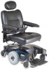
Owner's Operator and Maintenance Manual Pronto® M51™and M61™with SureStep® DEALER: This manual MUST be given to the user of the product. USER: BEFORE using this product, read this manual and save for future reference. For more information regarding Invacare products, parts, and services, please - Invacare M51PSR20B | Owners Manual - Page 2
M50/M51/M61 Service Manual MK5™NX™Electronics Manual (M51 Wheelchairs) MK6i™Electronics Field Reference Guide (M61 Wheelchairs) PART NUMBER 1125075 1110532 1141471 NOTE: Updated versions of this manual are available on www.invacare.com. Pronto® M51™and M61™with SureStep® 2 Part No 1125085 - Invacare M51PSR20B | Owners Manual - Page 3
TROUBLESHOOTING 23 Safety Inspection Checklists...23 Troubleshooting Guide ...25 Checking Battery Charge Level...28 SECTION 5-WHEELCHAIR OPERATION 29 Operating the Wheelchair...29 Adjusting the Speed ...30 Using Seat Positioning Strap ...43 Part No 1125085 3 Pronto® M51™and M61™with SureStep® - Invacare M51PSR20B | Owners Manual - Page 4
warranty.invacare.com Please have your model number and purchase date available to complete your registration. Any registration information you submit will only be used by Invacare Corporation and protected as required by applicable laws and regulations. Pronto® M51™and M61™with SureStep® 4 Part - Invacare M51PSR20B | Owners Manual - Page 5
Invacare products are specifically designed and manufactured for use in conjunction with Invacare accessories. Accessories designed by other manufacturers have not been tested by Invacare and are not recommended for use with Invacare products. Part No 1125085 5 Pronto® M51™and M61™with SureStep - Invacare M51PSR20B | Owners Manual - Page 6
from other chairs previously used. This power wheelchair has Invacare's SureStep technology, a feature that provides the chair with optimum traction and stability when driving forward over transitions and thresholds of up to 2-inches. The following warnings apply specifically to the SureStep Feature - Invacare M51PSR20B | Owners Manual - Page 7
LABEL LOCATION LABEL LOCATION M51 Wheelchairs Serial label located inside the wheelchair frame M61 Wheelchairs Part No 1125085 7 Pronto® M51™and M61™with SureStep® - Invacare M51PSR20B | Owners Manual - Page 8
inches 19 to 21 inches WITH ELEVATING SEAT (M61): OVERALL WIDTH: OVERALL HEIGHT: OVERALL LENGTH: DRIVE WHEELS/ TIRES: CASTER: FOOTRESTS/ LEGRESTS: *WEIGHT W/O BATTERIES: W/BATTERIES (U1): 21 to 23 inches + up to 145 to 170 lbs 192 to 217 lbs Pronto® M51™and M61™with SureStep® 8 Part No 1125085 - Invacare M51PSR20B | Owners Manual - Page 9
maximum chair weight rating using largest batteries battery discharge indicator on the joystick to determine the range of their wheelchair. Refer to Battery Charger Operation on page 67 for more information about the battery discharge indicator. Part No 1125085 9 Pronto® M51™and M61™with SureStep - Invacare M51PSR20B | Owners Manual - Page 10
the wheelchair may tip over. DO NOT make sharp turns in the forward or reverse direction at excessive speed. Failure to observe this warning can cause the wheelchair to tip over and may result in injury to users, bystanders and/or damage to product. Pronto® M51™and M61™with SureStep® 10 Part No - Invacare M51PSR20B | Owners Manual - Page 11
user or damage to the wheelchair. Make sure the detent balls of the quick‐release pin are fully released beyond the outer edge of the tube before operating the wheelchair. Otherwise, injury and/or damage may result. Keep detent balls clean. Part No 1125085 11 Pronto® M51™and M61™with SureStep® - Invacare M51PSR20B | Owners Manual - Page 12
specifications contained in this manual are based on the use of deep cycle gel cell or sealed lead acid batteries. Invacare strongly recommends their use as the power source for this unit. Carefully read battery/battery charger information prior to installing, servicing or operating your wheelchair - Invacare M51PSR20B | Owners Manual - Page 13
. If occupant uses said wheelchair as a weight training apparatus, Invacare shall not be liable for bodily injury and the warranty is void. Weight Limitation The M51 and M61 wheelchairs with SureStep have a weight limitation of 300 lbs. Part No 1125085 13 Pronto® M51™and M61™with SureStep® - Invacare M51PSR20B | Owners Manual - Page 14
they are ON, even when not being used. 2) Medium-range mobile transceivers, such as those used in police cars, fire trucks, ambulances electric shavers and hair dryers, so far as we know, are not likely to cause EMI problems to your powered wheelchair. Pronto® M51™and M61™with SureStep® 14 Part - Invacare M51PSR20B | Owners Manual - Page 15
UNINTENDED BRAKE RELEASE OR POWERED WHEELCHAIR MOVEMENT WHICH COULD RESULT IN SERIOUS INJURY. 1) Do not operate hand-held transceivers (transmitters of this wheelchair as manufactured by Invacare may adversely affect the EMI immunity levels. Part No 1125085 15 Pronto® M51™and M61™with SureStep® - Invacare M51PSR20B | Owners Manual - Page 16
only as a "basic" guide. The techniques that are discussed on the following pages have been used successfully by many. Individual wheelchair users often develop skills to deal with daily living activities that may differ from those described in this manual. Invacare recognizes and encourages each - Invacare M51PSR20B | Owners Manual - Page 17
positions will cause wheelchair to feel unstable. 2-inch Bump or Threshold FIGURE 3.1 Coping With Everyday Obstacles CAUTION Be aware of condition of ramp. Traction will be diminished/nonexistent on a slippery surface. Proceed with caution. Part No 1125085 17 Pronto® M51™and M61™with SureStep® - Invacare M51PSR20B | Owners Manual - Page 18
of detachable parts such as arms or legrests. These must NEVER be used to move the wheelchair or as lifting supports, as they ƽ WARNING M61 WHEELCHAIRS ONLY - Pinch point may occur when lowering the elevating seat. Make sure the hands Points Pronto® M51™and M61™with SureStep® 18 Part No 1125085 - Invacare M51PSR20B | Owners Manual - Page 19
when it is necessary to move an unoccupied power wheelchair up or down the stairs. Invacare recommends using two assistants and making thorough preparations. Use only secure, nondetachable parts for hand-hold supports. It is strongly recommended to lift the wheelchair only by the rear frame and the - Invacare M51PSR20B | Owners Manual - Page 20
front forks as hand hold supports, transfer the wheelchair base to desired location. Refer to FIGURE 3.4. 7. Using non‐removable (nondetachable) parts, transfer the seat and any accessories to desired location. 8. Reinstall any accessories that were removed in STEP 3. 9. Reinstall the seat. Refer to - Invacare M51PSR20B | Owners Manual - Page 21
rear casters pointing away from it. 2. After the wheelchair is positioned properly for transfer, verify that the motor transfer, little or no seat platform will be beneath you. Use a transfer board if at all possible. Reaching, Leaning Part No 1125085 21 Pronto® M51™and M61™with SureStep® - Invacare M51PSR20B | Owners Manual - Page 22
over. NOTE: For this procedure, refer to For this procedure, refer to FIGURE 3.7. Position wheelchair as close as possible to the desired object. Point the front AND rear casters rearward to position. FIGURE 3.7 Reaching and Bending - Backward Pronto® M51™and M61™with SureStep® 22 Part No 1125085 - Invacare M51PSR20B | Owners Manual - Page 23
SECTION 4-SAFETY INSPECTION/ TROUBLESHOOTING NOTE: Every six months or as necessary take your wheelchair to a qualified dealer for a thorough inspection and servicing. Regular cleaning will reveal loose or worn parts and enhance the smooth operation of your wheelchair. To operate properly and safely - Invacare M51PSR20B | Owners Manual - Page 24
charger AC power cord for damage. Replace if necessary. ❑ Ensure casters are free of debris. ❑ Inspect electrical components for signs of corrosion. Replace if corroded or damaged. ❑ Check that all labels are present and legible. Replace if necessary. Pronto® M51™and M61™with SureStep® 24 Part No - Invacare M51PSR20B | Owners Manual - Page 25
sure elevate operates smoothly and properly. ❑ Make sure elevate systems drive with reduced speed when seat is in elevated position. Troubleshooting Guide NOTE: For additional troubleshooting information and explanation of error codes, refer to the Electronics Manual supplied with each wheelchair - Invacare M51PSR20B | Owners Manual - Page 26
displayed. Information Gauge Display Diagnostics DISPLAY Information Gauge Display DESCRIPTION DEFINITION COMMENTS All LEDs are off. Power is off. All LEDs are on. Power is on. Fewer than three LEDs on implies reduced battery charge. Pronto® M51™and M61™with SureStep® 26 Part No 1125085 - Invacare M51PSR20B | Owners Manual - Page 27
is connected properly. Contact Invacare/Dealer for service. Contact Invacare/Dealer for service. Contact Invacare/Dealer for service. Contact Invacare/Dealer for service. Wrong type of remote connected. Contact Invacare/Dealer for service. Part No 1125085 27 Pronto® M51™and M61™with SureStep® - Invacare M51PSR20B | Owners Manual - Page 28
batteries to the lowest level. Don't use randomly chosen batteries or chargers. Don't put new batteries into servcie before charging. Don't tip or tilt batteries. Don't tap on clamps and terminals with tools. Don't mismatch your battery and chargers. Pronto® M51™and M61™with SureStep® 28 Part - Invacare M51PSR20B | Owners Manual - Page 29
SECTION 5-WHEELCHAIR OPERATION SECTION 5-WHEELCHAIR OPERATION ƽ WARNING After any adjustments, repair or service and before use, make sure that all attaching hardware is tightened securely - otherwise injury or damage may result. Set-up/programming of the Electronic Control Unit is to be performed - Invacare M51PSR20B | Owners Manual - Page 30
Wheelchair To Move Right Rear of Wheelchair Joystick FIGURE 5.2 Using the Joystick to Drive the Wheelchair NOTE: For specific information about the joystick installed on the wheelchair ) ‐ Perform the following steps: i. Press and hold both Pronto® M51™and M61™with SureStep® 30 Part No 1125085 - Invacare M51PSR20B | Owners Manual - Page 31
, the safety feature slows the speed of the wheelchair by 80%. If the wheelchair operates at maximum speed while in an elevated position, DO NOT operate the wheelchair. Have the wheelchair serviced immediately by a qualified technician. Part No 1125085 31 Pronto® M51™and M61™with SureStep® - Invacare M51PSR20B | Owners Manual - Page 32
SECTION 5-WHEELCHAIR OPERATION NOTE: For this procedure, refer to FIGURE 5.5 on page 32. NOTE: This procedure applies to M61 wheelchairs only. 1. Make sure the wheelchair is on a level surface. 2. Lower the Seat FIGURE 5.5 Elevating the Seat Pronto® M51™and M61™with SureStep® 32 Part No 1125085 - Invacare M51PSR20B | Owners Manual - Page 33
SECTION 5-WHEELCHAIR OPERATION SPJ+ and SPJ+ w/ACC Joystick Switches and Indicators NOTE: For the following DETAIL "A" FRONT VIEW Charger/ Programming Input Service Indicator FIGURE 5.6 SPJ+ and SPJ+ w/ACC Joystick Switches and Indicators Part No 1125085 33 Pronto® M51™and M61™with SureStep® - Invacare M51PSR20B | Owners Manual - Page 34
the SPJ+ w/ACC joystick only. Press the mode button to switch from driving mode to elevate mode. Refer to Elevating the Seat on page 31. Pronto® M51™and M61™with SureStep® 34 Part No 1125085 - Invacare M51PSR20B | Owners Manual - Page 35
when a fault is detected by the control module. A specific number of flashes of the LEDs indicate the type of fault detected. Refer to Information Gauge Display Diagnostics on page 28 for the diagnostic indications of the wheelchair status. Part No 1125085 35 Pronto® M51™and M61™with SureStep® - Invacare M51PSR20B | Owners Manual - Page 36
the overall width of the wheelchair. 2. Reposition the arms until desired width is achieved. 3. Securely tighten the two lock knobs that secure the arms to the arm support tube. Pronto® M51™and M61™with SureStep® 36 Seat Arm Lock Knob Arm Support Tube FIGURE 6.2 Adjusting Width Part No 1125085 - Invacare M51PSR20B | Owners Manual - Page 37
to FIGURE 6.3. ƽ WARNING Pinch point may occur when adjusting the arm angle position. 6. Repeat STEPS 1‐5 for opposite armrest, if necessary. Arm Pad Pinch Point 1. Lift up the armrest. 2. Arm Frame Assembly FIGURE 6.4 Adjusting Height Part No 1125085 37 Pronto® M51™and M61™with SureStep® - Invacare M51PSR20B | Owners Manual - Page 38
Make sure the flip back armrest release and height adjustment levers are in the locked position before using the wheelchair. on flip back armrest to make sure the armrest is locked in place. 5. Repeat STEPS 1‐4 for opposite flip back armrest. Pronto® M51™and M61™with SureStep® 38 Part No 1125085 - Invacare M51PSR20B | Owners Manual - Page 39
armrest is out of the way. 4. Repeat STEPS 1‐3 for opposite flip back armrest, if necessary. Positioning Flip Back Armrests for Use 1. Make sure the flip back armrest release lever is in FIGURE 6.6 Positioning/Adjusting Flip Back Armrests Part No 1125085 39 Pronto® M51™and M61™with SureStep® - Invacare M51PSR20B | Owners Manual - Page 40
service and before use, make sure that all attaching hardware is tightened securely - otherwise injury or damage may result. Before performing any maintenance, adjustment or service is shown. Standard van seat operates the same way. Office Style Pronto® M51™and M61™with SureStep® 40 Part No 1125085 - Invacare M51PSR20B | Owners Manual - Page 41
to the desired position. 2. To lower the headrest, push the release tab towards the front of the wheelchair. Lower the headrest to the desired position. Headrest Release Tab Headrest Tube FIGURE 7.3 Adjusting the Headrest (Semi-Recline Only) Part No 1125085 41 Pronto® M51™and M61™with SureStep® - Invacare M51PSR20B | Owners Manual - Page 42
style van seat is shown. Standard van seat installs the same way. NOTE: ASBA Seat installs the same way. FIGURE 7.4 Removing/Installing the Seat Assembly Pronto® M51™and M61™with SureStep® 42 Part No 1125085 - Invacare M51PSR20B | Owners Manual - Page 43
strap. The seat positioning strap is a positioning belt only. It is not designed for use as a safety device withstanding high stress loads such as auto or aircraft safety belts. If FIGURE 7.5 Replacing the Seat Positioning Strap - Van Seat Part No 1125085 43 Pronto® M51™and M61™with SureStep® - Invacare M51PSR20B | Owners Manual - Page 44
Seat Pan Seat Positioning Strap Front of Seat Frame Quick Release Pin Tab Seat Rail Spacer Locknut FIGURE 7.6 Replacing the Seat Positioning Strap - ASBA Seat Pronto® M51™and M61™with SureStep® 44 Part No 1125085 - Invacare M51PSR20B | Owners Manual - Page 45
to FIGURE 8.1 on page 46. Removing 1. Remove the quick release pin that secures the footboard assembly to the wheelchair frame by depressing the button while sliding the pin out. 2. Remove the footboard assembly from the wheelchair frame. Part No 1125085 45 Pronto® M51™and M61™with SureStep® - Invacare M51PSR20B | Owners Manual - Page 46
Installing ƽ WARNING Make sure the detent balls of the quick-release pin are fully released beyond the outer edge of the tube before operating the wheelchair. Otherwise, injury and/or nut and washer to secure the mounting screw in place. Pronto® M51™and M61™with SureStep® 46 Part No 1125085 - Invacare M51PSR20B | Owners Manual - Page 47
to the wheelchair frame. ƽ WARNING Make sure the detent balls of the quick-release pin are fully released and beyond the outer edge of the tube before operating the wheelchair. Otherwise, FIGURE 8.3 Adjusting the Footboard Assembly - Depth Part No 1125085 47 Pronto® M51™and M61™with SureStep® - Invacare M51PSR20B | Owners Manual - Page 48
of the wheelchair when locked in place. 5. Repeat STEPS 1‐4 for opposite side of wheelchair. Hinge Pins Telescoping Front Rigging Support Front Rigging Release Lever Front Rigging Hinge Plate FIGURE 9.1 Installing/Removing Front Riggings Pronto® M51™and M61™with SureStep® 48 Part No 1125085 - Invacare M51PSR20B | Owners Manual - Page 49
the wheelchair. Refer to Installing/Removing Front Riggings on page 48. 8. Reinstall any accessories onto the footrest(s). Locknut Coved Washer Footrest Support Coved Washer Hex Bolt Lower Footrest FIGURE 9.2 Adjusting Footrest Height - Model PHWH93 Part No 1125085 49 Pronto® M51™and M61™with - Invacare M51PSR20B | Owners Manual - Page 50
footrest support. 4. Repeat STEPS 1‐3 for the opposite side of the wheelchair STEPS 1‐6 to reassemble. FIGURE 9.4 Replacing Heel Loops NOTE: When securing heel loop to lower footrest, tighten the phillips screw and locknut until the spacer is secure. Pronto® M51™and M61™with SureStep® 50 Part - Invacare M51PSR20B | Owners Manual - Page 51
mounting hole of the telescoping front rigging support with the front mounting hole in the seat frame tubes to achieve the desired depth as shown in FIGURE 9.6. NOTE: The footplate will be on the inside of the wheelchair when locked in place. Part No 1125085 51 Pronto® M51™and M61™with SureStep® - Invacare M51PSR20B | Owners Manual - Page 52
Using the two socket bolts and locknuts, secure the telescoping front rigging support to the seat frame as shown in FIGURE 9.6. 5. If necessary, repeat STEPS 2‐4 on remaining telescoping front rigging support Supports - Office Style Seat Pronto® M51™and M61™with SureStep® 52 Part No 1125085 - Invacare M51PSR20B | Owners Manual - Page 53
the telescoping front rigging support to the seat frame as shown in FIGURE 9.7. 5. If necessary, repeat STEPS 2‐4 on remaining telescoping front rigging support. 6. Reinstall the seat. Refer to Removing/Installing the Seat Assembly on page 35. Part No 1125085 53 Pronto® M51™and M61™with SureStep® - Invacare M51PSR20B | Owners Manual - Page 54
Rigging Support 8 7 65 4 32 Not Used support to one of three depth positions. • Remove existing telescoping front rigging. 3. Secure telescoping front rigging at desired depth with existing two mounting screws, spacers, and locknuts. Securely tighten. Pronto® M51™and M61™with SureStep® 54 Part - Invacare M51PSR20B | Owners Manual - Page 55
rigging supports can be positioned at different depths depending on the need of the user. Mounting Screws Spacer Locknut Spacer Locknut Telescoping Front Tube FIGURE 9.8 Adjusting/Replacing Telescoping Front Rigging Supports - ASBA Seat Part No 1125085 55 Pronto® M51™and M61™with SureStep® - Invacare M51PSR20B | Owners Manual - Page 56
Wheelchairs Only ‐ Secure the joystick cable using the clip on the top shroud. 4. Install the seat assembly. Refer to Removing/Installing the Seat Assembly on page 42. 5. Connect the joystick. Refer to Disconnecting/Connecting the Joystick on page 74. Pronto® M51™and M61™with SureStep® 56 Part - Invacare M51PSR20B | Owners Manual - Page 57
Release Levers ‐ Push the motor lock handles towards the front of the wheelchair (drive position). NOTE: This allows the motors to drive the wheels. NOTE: It may be necessary to rock the wheels slightly until the motor release lever engages. Part No 1125085 57 Pronto® M51™and M61™with SureStep® - Invacare M51PSR20B | Owners Manual - Page 58
with existing mounting screw, two washers and locknut (FIGURE 10.3). Securely tighten. Locknut Mounting Screw Washer Washer Caster FIGURE 10.3 Replacing Front/Rear Caster Assemblies Pronto® M51™and M61™with SureStep® 58 Part No 1125085 - Invacare M51PSR20B | Owners Manual - Page 59
locknut according to freedom of caster swing. 3. Test wheelchair for maneuverability. 4. Readjust locknut if necessary, and repeat STEPS 2‐3 until correct. 5. Snap dust cover into the Fork Caster Headtube Washer FIGURE 10.4 Adjusting Forks Part No 1125085 59 Pronto® M51™and M61™with SureStep® - Invacare M51PSR20B | Owners Manual - Page 60
or service and before use, make sure that all attaching hardware is tightened securely - otherwise injury or damage may result. Make sure power to the wheelchair is Off before performing this section. The use of rubber gloves is recommended when working with batteries. Invacare strongly recommends - Invacare M51PSR20B | Owners Manual - Page 61
battery handle when lifting the battery. It is the most convenient method and assures that the battery acid will not spill. It also helps to prolong the life of the battery. DO NOT tip the batteries. Keep the batteries in an upright position. Part No 1125085 61 Pronto® M51™and M61™with SureStep - Invacare M51PSR20B | Owners Manual - Page 62
battery from the controller (BLACK connector). 6. Disconnect the rear battery from the front battery (RED and BLACK connectors). 7. Lift rear and front battery out of the battery tray using the battery /Installing the Seat Assembly on page 57. Pronto® M51™and M61™with SureStep® 62 Part No 1125085 - Invacare M51PSR20B | Owners Manual - Page 63
battery harness with fuse. The POSITIVE (+) battery cable MUST connect to the POSITIVE (+) battery terminal, otherwise serious damage will occur to the electrical system. The use of rubber gloves is recommended when working with batteries. Part No 1125085 63 Pronto® M51™and M61™with SureStep - Invacare M51PSR20B | Owners Manual - Page 64
Removing/Installing Batteries from/ into Battery Tray on page 61. NOTE: New batteries MUST be fully charged before using, otherwise the life of the batteries will be reduced. 6. If necessary, charge the battery. Refer to Charging Batteries on page 66. Pronto® M51™and M61™with SureStep® 64 Part No - Invacare M51PSR20B | Owners Manual - Page 65
U1 Battery RED Connectors BLACK Connector to Controller U1 Battery Tie-wraps BLACK Connectors NOTE: Handles on batteries removed for clarity. U1 Batteries FIGURE 11.3 Connecting/Disconnecting Battery Cables Plug into controller Part No 1125085 65 Pronto® M51™and M61™with SureStep® - Invacare M51PSR20B | Owners Manual - Page 66
. Doing so will reduce the life of the batteries. Read and carefully follow the individual instructions for each charger (supplied or purchased). If charging instructions are not supplied, consult a qualified technician for proper procedures. Pronto® M51™and M61™with SureStep® 66 Part No 1125085 - Invacare M51PSR20B | Owners Manual - Page 67
instructions are not supplied, consult a qualified technician for proper procedures. NEVER leave the charger unattended when the charger circuit breaker is tripping. Ꮨ DANGER Use of improper extension cord could result in risk of fire and electric shock. Part No 1125085 67 Pronto® M51™and M61 - Invacare M51PSR20B | Owners Manual - Page 68
the male connector of the AC power cord from the wall outlet and then unplug the female connector of the AC power cord from the AC receptacle on the charger. ƽ WARNING DO NOT operate wheelchair with AC power cord attached to the wheelchair. Pronto® M51™and M61™with SureStep® 68 Part No 1125085 - Invacare M51PSR20B | Owners Manual - Page 69
the life of the batteries. CAUTION Only use a charger approved by Invacare when charging through the joystick on this wheelchair model. DO NOT use an independent charger with an output rating of over 8A (Amps). Otherwise, damage may occur. Part No 1125085 69 Pronto® M51™and M61™with SureStep® - Invacare M51PSR20B | Owners Manual - Page 70
with the wheelchair. 1. Attach the battery charger connector to the charger port on the front of the joystick. 2. Plug the charger's AC power cord or Programming Port FIGURE 11.5 Charging Using An Independent Charger Plugged Into The Joystick Pronto® M51™and M61™with SureStep® 70 Part No 1125085 - Invacare M51PSR20B | Owners Manual - Page 71
or service and before use, make sure that all attaching hardware is tightened securely - otherwise injury or damage may result. Before performing any maintenance, adjustment or service verify to Disconnecting/Connecting the Joystick on page 74. Part No 1125085 71 Pronto® M51™and M61™with SureStep® - Invacare M51PSR20B | Owners Manual - Page 72
release the joystick mounting tube from the mounting bracket. 2. Remove the joystick from the wheelchair. 3. Remove the three hex mounting screws, spacers and locknuts that secure the mounting the mounting bracket on the opposite arm frame. Pronto® M51™and M61™with SureStep® 72 Part No 1125085 - Invacare M51PSR20B | Owners Manual - Page 73
Using tube. 2. Remove the joystick mounting tube from the wheelchair. 3. Remove the three hex screws that secure joystick and opened hole half clamp on the opposite arm tube. Make sure threaded hole half clamp is on the inside of arm tube Part No 1125085 73 Pronto® M51™and M61™with SureStep® - Invacare M51PSR20B | Owners Manual - Page 74
together. 1. Hold the light GREY collar portion of the joystick connector with one hand and the controller connector on the wheelchair in the other and align them. 2. Lightly push to engage the joystick connector and the controller connector. Pronto® M51™and M61™with SureStep® 74 Part No 1125085 - Invacare M51PSR20B | Owners Manual - Page 75
Joystick Cable SECTION 12-ELECTRONICS Joystick Office Style Seat Controller Connector Light Grey Collar Joystick Connector FIGURE 12.4 Disconnecting/Connecting the Joystick Part No 1125085 75 Pronto® M51™and M61™with SureStep® - Invacare M51PSR20B | Owners Manual - Page 76
or service and before use, make sure that all attaching hardware is tightened securely - otherwise injury or damage may result. Before performing any maintenance, adjustment or service verify 13.1 Installing/Removing the Crutch/Cane Holder Pronto® M51™and M61™with SureStep® 76 Part No 1125085 - Invacare M51PSR20B | Owners Manual - Page 77
NOT use the oxygen holder for anything other than its intended purpose of supporting an oxygen cylinder - otherwise, injury or damage may occur. DO NOT attempt to modify the oxygen holder to fit any other type of wheelchair. The oxygen holder was designed specifically for Invacare wheelchairs only - Invacare M51PSR20B | Owners Manual - Page 78
service and before use, make sure that all attaching hardware is tightened securely. The installation of the walker holder onto the back of the wheelchair seat increases the length of the wheelchair Installing/Removing/Using the Walker Holder Pronto® M51™and M61™with SureStep® 78 Part No 1125085 - Invacare M51PSR20B | Owners Manual - Page 79
. Invacare warrants all electronics and electrical components (excluding batteries), INVACARE. THE WARRANTY SHALL NOT APPLY TO PROBLEMS ARISING FROM NORMAL WEAR AND TEAR OR FAILURE TO ADHERE TO THE PRODUCT INSTRUCTIONS. A CHANGE IN OPERATING Part No 1125085 79 Pronto® M51™and M61™with SureStep® - Invacare M51PSR20B | Owners Manual - Page 80
'S CONTROL, AND SUCH EVALUATION WILL BE SOLELY DETERMINED BY INVACARE. THE WARRANTY SHALL NOT APPLY TO PROBLEMS ARISING FROM NORMAL WEAR AND TEAR OR FAILURE TO ADHERE TO THE PRODUCT INSTRUCTIONS. A CHANGE IN OPERATING NOISE, PARTICULARLY RELATIVE TO MOTORS AND GEARBOXES DOES NOT CONSTITUTE A FAILURE
-
 1
1 -
 2
2 -
 3
3 -
 4
4 -
 5
5 -
 6
6 -
 7
7 -
8
-
9
-
10
-
11
-
12
-
13
-
14
-
15
-
16
-
17
-
18
-
19
-
20
-
21
-
22
-
23
-
24
-
25
-
26
-
27
-
28
-
29
-
30
-
31
-
32
-
33
-
34
-
35
-
36
-
37
-
38
-
39
-
40
-
41
-
42
-
43
-
44
-
45
-
46
-
47
-
48
-
49
-
50
-
51
-
52
-
53
-
54
-
55
-
56
-
57
-
58
-
59
-
60
-
61
-
62
-
63
-
64
-
65
-
66
-
67
-
68
-
69
-
70
-
71
-
72
-
73
-
74
-
75
-
76
-
77
-
78
-
79
-
80
 |
 |
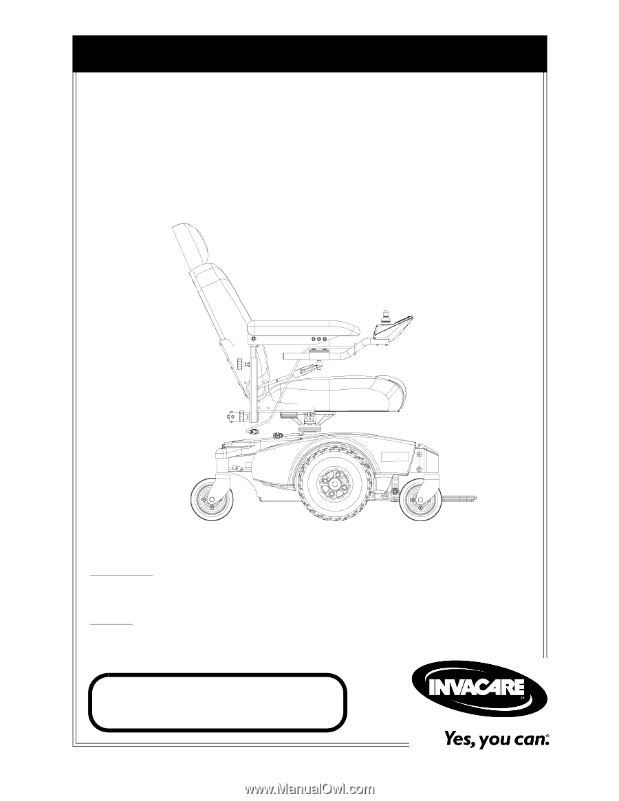
Owner’s Operator and Maintenance Manual
DEALER:
This manual MUST be given to
the user of the product.
USER:
BEFORE using this product, read this
manual and save for future reference.
For more information regarding
Invacare products, parts, and services,
please visit www.invacare.com
Pronto
®
M51
™
and
M61
™
with SureStep
®