Invacare ORBITS Owners Manual
Invacare ORBITS Manual
 |
View all Invacare ORBITS manuals
Add to My Manuals
Save this manual to your list of manuals |
Invacare ORBITS manual content summary:
- Invacare ORBITS | Owners Manual - Page 1
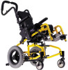
ORBIT SEAT OPTION ON POWER TIGER BASE OWNER'S OPERATOR AND MAINTENANCE MANUAL - Invacare ORBITS | Owners Manual - Page 2
MANUAL AND THE OWNER'S MANUAL MANUAL SUPERCEDE ANY DUPLICATED PROCEDURES FOUND IN THE POWER TIGER OWNER'S MANUAL, PART NUMBER 1045938. THE INITIAL SET UP OF THIS WHEELCHAIR MUST BE PERFORMED BY AN AUTHORIZED INVACARE POSITIONING STRAPS Invacare is Invacare's position that SEATING POSITIONING STRAP - Invacare ORBITS | Owners Manual - Page 3
THE LOCKING MECHANISM IN THE BACK CANE 15 INSTALLING/REMOVING STROLLER HANDLES 15 FOLDING/UNFOLDING THE BACK CANES 16 REMOVING/INSTALLING DEALER ADJUSTMENTS - STABILITY 24 STABILITY OVERVIEW...24 CHANGING THE CASTER POSITION 24 CHANGING THE BACK ANGLE ...24 CHANGING THE SEAT DEPTH...25 - Invacare ORBITS | Owners Manual - Page 4
Overall Depth (w/o front riggings): F Overall Height: I C Seat Width: A Seat Depth: T I Seat-to-Floor Height: O Back Style and Height: N S Arm Styles: ORBIT SEAT OPTION ON POWER TIGER BASE *23-inches (including joystick) *30-inches *41-inches 10 to 16-inches (in one {1} inch increments - Invacare ORBITS | Owners Manual - Page 5
the Power Tiger Owner’s Manual, part number S 1045938. S Invacare recommends that Action wheelchair users NOT be transported in vehicles of any kind base frame plate until an audible click is heard. See DETAIL "A". while in wheelchairs. As of this date, the Depart- 2. Visually into position. - Invacare ORBITS | Owners Manual - Page 6
positive lock. B. Install the T-arms. Refer to REMOVING/IN- D 8. Install the footrests. Refer to FRONT RIGGINGS in STALLING THE T-ARMS in PROCEDURE 3 of I PROCEDURE 2 of this manual. this manual 4 of this manual. S TERIES on page 43 in the Power Tiger Owner’s Manual, part number 1045938. S - Invacare ORBITS | Owners Manual - Page 7
Tube Height Adjustment I After ANY adjustments, repair or service and (FIGURE 2) N BEFORE use, make sure all Manual, part number 1045938. 2. Remove the hex screw and coved washer and position the lower footrest assembly to the desired height. 3. Align the mounting hole in the footrest support - Invacare ORBITS | Owners Manual - Page 8
inter- Tiger Owner’s Manual, part number 1045938. fere with the movement of the front casters. NOTE: Note the position of the attaching hardware this procedure. 90o Footrest Support Flat Screws Articulating Footplate Footplate Hinge Nylon Adjustment Screw 5. Position the footplate at the - Invacare ORBITS | Owners Manual - Page 9
hinge 180o. 3. Retighten the two (2) flat screws, washers and locknuts. Footrest Support FRONT VIEW OF N FOOTPLATE T AND FOOTREST Footplate SUPPORT. R I G G I N G NOTE: The settings for positioning the articulating FIGURE 7 - ADJUSTABLE ANGLE FLIP-UP S footplates on the half - Invacare ORBITS | Owners Manual - Page 10
loop to the footplate. 4. Repeat STEPS 1-3 for opposite telescoping front 2. Position the mounting holes of the NEW heel loop frame tube. with the LOOP REPLACEMENT on page 32 in the Power Tiger Owner’s Manual, part number 1045938. Composite Footplates 1. Remove the hex screw and coved washer - Invacare ORBITS | Owners Manual - Page 11
. Refer to ADJUSTING THE T-ARMS in this instruction sheet. 7. Repeat STEPS 2-6 for the opposite service and BEFORE use, make sure all attaching hardware is Installing tightened securely. 1. Position INSTALLING THE T-ARMS in this procedure of the manual. T-arm Clamp T-arm Socket Inserts Removing - Invacare ORBITS | Owners Manual - Page 12
of the wheelchair.) Outside TArm Post T-Arm Release Lever - Locked Position FIGURE 3 - ADJUSTING THE T-ARMS - HEIGHT T-Arm Socket Slot outside of the wheelchair. 2. Slide the T-arm to one (1) of the eight (8) positions. NOTE: If the inside T-arm post does not slide up and down in the outside - Invacare ORBITS | Owners Manual - Page 13
- 3. Remove the EXISTING locking lever and spring from cedure of the manual. the bottom bracket. 2. Remove the two (2) bottom socket screws that one (1) of three (3) mounting are inside the notch in the locking lever. positions in the side guard. 6. Line up the mounting holes in the NEW locking - Invacare ORBITS | Owners Manual - Page 14
joystick mounting tube. R NOTE: Illustration depicts the locked position of the reM lease lever facing forward and the unlocked position fac- S ing rearward. The unlocked and locked positions will not always be as shown. Positions shown for reference only. Release Lever 4. Remove joystick from - Invacare ORBITS | Owners Manual - Page 15
FIGURE 1 - REPLACING THE LOCKING E After ANY adjustments, repair or service and BE- MECHANISM IN THE BACK CANE E FORE use, make sure the manual. 2. Slide the stroller handle into the back canes. 3. Align the mounting holes of the stroller handle and the back canes. 4. Secure stroller handle - Invacare ORBITS | Owners Manual - Page 16
the wheelchair, refer to your particular seating system manufacturer's Owner's Manual for installation and removal of the seating system. 1. If so 3. Remove existing seat pan and discard. Handle Wheellock Installing 1. Position the NEW seat pan on crossmembers. 2. Secure with the existing - Invacare ORBITS | Owners Manual - Page 17
tighten the locknut WARNING After ANY adjustments, repair or service and BE- slightly. Repeat STEP 4 until there is 38 in the Power Tiger Owner’s Manual, part number 1045938. Periodically, the tires will EXISTING caster from the fork. Installing 1. Position the new/existing caster into the fork. - Invacare ORBITS | Owners Manual - Page 18
adjusted by an authorized Invacare dealer or qualified technician. Make sure the occupant of the wheelchair is properly positioned. Always engage both wheel LOCKS in PROCEDURE 4 of this manual. 3. Move the locking mechanism on the release pedal to the unlocked position. See DETAIL "A". 4. Inform the - Invacare ORBITS | Owners Manual - Page 19
CANE in PROCEDURE 4 of this D manual. J WARNING After ANY adjustments, repair or service and BEFORE use, make sure all back canes and slide NEW spreader bar on. NOTE: Make sure the spreader bar is positioned on back canes so not to interfere with the back angle brackets. 6. Securely tighten - Invacare ORBITS | Owners Manual - Page 20
in this procedure of the manual. A D J U S T TO 15-INCH OR 16-INCH on page 51-57 in the Power Tiger Owner’s Manual, part number 1045938. 1. Remove the seat tighten. Before removing the crossmembers, note the mounting hole position of the crossmembers to the seat rails for proper reinstallation. - Invacare ORBITS | Owners Manual - Page 21
the base frame. Refer to DISASSEMBLY/ASSEMBLY in PROCEDURE 1 of this manual. inder handles and cables are not properly adjusted to ensure that the lock hold the 7. Remove anchor end of cable from front tab. tilted position. 8. To install perform the following: A. Reverse STEPS 1-7. Jam Nut - Invacare ORBITS | Owners Manual - Page 22
Remove the seat frame from the base frame. Refer to DISASSEMBLY/ASSEMBLY in PROCEDURE 1 A D NOTE: Rotating the cable adjuster COUNTERCLOCK- of this manual. WISE will produce slack in the cable. 2. Disconnect the cable from the tilt mechanism. Refer J U 2. Remove anchor end of cable from back - Invacare ORBITS | Owners Manual - Page 23
tilt mechanisms. Refer to REMOVING/INSTALLING/ADJUSTING THE CABLE ASSEMBLY in this procedure of the manual. 5. Adjustthecableassembly.Referto ADJUSTING THE CABLE ASSEMBLY in this procedure of the manual. 6. Install the seat frame from the base frame. Refer to DISASSEMBLY/ASSEMBLY in PROCEDURE 1 of - Invacare ORBITS | Owners Manual - Page 24
adjustments, repair or service and BE- S FORE use, make sure all attaching hardware is ALWAYS USE THIS MOUNTING POSITION DO NOT USE THESE adjustments BILITY OVERVIEW in this procedure of the manual. T MUST be performed by an authorized Invacare A dealer or qualified technician. 1. Loosen, - Invacare ORBITS | Owners Manual - Page 25
E NOTE: This procedure replaces SEAT DEPTHADJUST- R MENT on page 49 in the Power Tiger Owner’s Manual, part number 1045938. A D USE THE FOLLOWING MOUNTING HOLES FOR 1. Determine the necessary back position for the de- J ALLOWABLE BACK ANGLES sired seat depth. Refer to the FIGURE 5 for proper - Invacare ORBITS | Owners Manual - Page 26
15 14 13 12 11 10 Hole for Front Riggings J U BACK POSITION FOR 15-INCH SEAT DEPTH BACK POSITION FOR 11-INCH SEAT DEPTH S T M E N Rear of Seat 18 17 16 15 14 13 12 11 10 Hole for Front Riggings T BACK POSITION FOR 13-INCH SEAT DEPTH Y Rear of WARNING: Front Seat Never Use These - Invacare ORBITS | Owners Manual - Page 27
equipped. Platform A D NOTE: Refer to your particular seating system manufacturer's Owner's Manual for removal of the seat- XX XX J U ing system. S 2. Remove and and and and Rear Crossmember 8 9 10 11 12 3. Position the seat plate assembly at the mounting holes for the desired pivot - Invacare ORBITS | Owners Manual - Page 28
Mounting Mounting T Hole 8 Hole 1 Mounting Mounting A Hole 11 Hole 4 B I XX XX XX XX XX XX L I T Y POSITION 2 USE MOUNTING HOLES NUMBER 2 AND 9 POSITION 5 USE MOUNTING HOLES NUMBER 5 AND 12 Mounting Hole 9 Mounting Hole 2 XX XX XX Mounting Hole 12 Mounting Hole 5 XX XX - Invacare ORBITS | Owners Manual - Page 29
Seat widths are listed down the left hand side. developed to show the difference in weight distribution NOTE: Each box contains the allowable 110o 80o-110o 80o-110o 80o-110o 80o-110o 80o-105o I T ADJUSTABLE PIVOT POINT POSITION #2 Y SEAT WIDTH SEAT DEPTH 10 11 12 13 14 15 16 10 N/A - Invacare ORBITS | Owners Manual - Page 30
12 U S 13 T 14 M E 15 N 16 T S ADJUSTABLE PIVOT POINT POSITION #3 SEAT DEPTH 10 11 12 13 14 N/A N/A 85o-110o 80o-110o 80o-110o 110o 80o-110o 80o-110o 80o-110o 80o-110o 80o-110o 80o-110o ADJUSTABLE PIVOT POINT POSITION #4 SEAT WIDTH 10 S T 11 A 12 B 13 I 14 L I 15 - Invacare ORBITS | Owners Manual - Page 31
80o-110o 80o-110o 80o-100o 80o-95o N/A N T S ADJUSTABLE PIVOT POINT POSITION #2 SEAT WIDTH 10 11 12 13 14 15 16 SEAT WIDTH 10 11 12 -110o 80o-110o 80o-110o 80o-110o 80o-100o 80o-95o T Y ADJUSTABLE PIVOT POINT POSITION #3 SEAT DEPTH 10 11 12 13 14 15 16 N/A N/A 85o-110o 80o-110o - Invacare ORBITS | Owners Manual - Page 32
PROCEDURE 8 DEALER ADJUSTMENTS - STABILITY STABILITY ADJUSTMENT WITH A KSS SEATING SYSTEM D E A L E R SEAT WIDTH ADJUSTABLE PIVOT POINT POSITION #4 SEAT DEPTH 10 11 12 13 14 15 16 A 10 D J 11 U 12 S T 13 M 14 E N 15 T 16 S N/A N/A N/A N/A 90o-110o 80o-110o 80o- - Invacare ORBITS | Owners Manual - Page 33
NOTES NOTES N O T E S 33 - Invacare ORBITS | Owners Manual - Page 34
NOTES N O T E S NOTES 34 - Invacare ORBITS | Owners Manual - Page 35
, OR TO A PRODUCT DAMAGED BY CIRCUMSTANCES BEYOND INVACARE’S CONTROL, AND SUCH EVALUATION WILL BE SOLELY DETERMINED BY INVACARE. THE WARRANTY SHALL NOT APPLY TO PROBLEMS ARISING FROM NORMAL WEAR OR FAILURE TO ADHERE TO THESE INSTRUCTIONS. THE FOREGOING WARRANTY IS EXCLUSIVE AND IN LIEU OF ALL - Invacare ORBITS | Owners Manual - Page 36
INVACARE CORPORATION l 39350 Taylor Parkway l North Ridgeville, OH 44039 Customer Service (800) 333-6900 l Technical Support (800) 832-4707 Form No. 98-303 Part No. 1083067 REV B (2) - 6/99 Printed in U.S.A.
-
 1
1 -
 2
2 -
 3
3 -
 4
4 -
 5
5 -
 6
6 -
 7
7 -
8
-
9
-
10
-
11
-
12
-
13
-
14
-
15
-
16
-
17
-
18
-
19
-
20
-
21
-
22
-
23
-
24
-
25
-
26
-
27
-
28
-
29
-
30
-
31
-
32
-
33
-
34
-
35
-
36
 |
 |

OWNER'S OPERATOR AND
MAINTENANCE MANUAL
ORBIT SEAT OPTION
ON
POWER TIGER BASE