Invacare TDXSIV-2 Owners Manual 2
Invacare TDXSIV-2 Manual
 |
View all Invacare TDXSIV-2 manuals
Add to My Manuals
Save this manual to your list of manuals |
Invacare TDXSIV-2 manual content summary:
- Invacare TDXSIV-2 | Owners Manual 2 - Page 1
Invacare® TDX®SI Series Invacare TDX SI Invacare TDX SI-2 Invacare TDX SI-HD Power Wheelchair Base User Manual EN This manual MUST be given to the user of the product. BEFORE using this product, read this manual and save for future reference. - Invacare TDXSIV-2 | Owners Manual 2 - Page 2
duplication or modification in whole or in part is prohibited without prior written permission from Invacare. Trademarks are identified by ™ and ®. All trademarks are owned by or licensed to Invacare Corporation or its subsidiaries unless otherwise noted. Invacare® TDX®SI Series 2 Part No 1154294 - Invacare TDXSIV-2 | Owners Manual 2 - Page 3
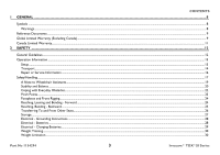
Operation Information ...13 Setup ...13 Transport...14 Repair or Service Information ...16 Safety/Handling ...17 A Note to Wheelchair Instructions...28 Electrical - Batteries ...28 Electrical - Charging Batteries...29 Weight Training...30 Weight Limitation ...30 Part No 1154294 3 Invacare® TDX®SI - Invacare TDXSIV-2 | Owners Manual 2 - Page 4
Joystick Switches and Indicators ...43 On/Off Button ...44 Speedometer...44 Speed Control Buttons...44 Joystick ...45 Charger/Programming Input...45 Information Gauge Display ...45 Service Indicator ...45 Invacare® TDX®SI Series 4 Part No 1154294 - Invacare TDXSIV-2 | Owners Manual 2 - Page 5
...59 TDX SI/TDX SI-2 without SSD Motors and All TDS SI with SSD Motors...59 TDX SI-HD without SSD Motors...60 Disengaging/Engaging the Wheel locks ...61 Engaging...61 Disengaging...61 Removing/Installing the Footboard ...62 Removing ...62 Installing...62 Part No 1154294 5 Invacare® TDX®SI Series - Invacare TDXSIV-2 | Owners Manual 2 - Page 6
64 About Transport Ready Packages...65 Compliance Information...66 Specifications...66 Positioning the Wheelchair in the Vehicle...67 Securement Service Inspection ...77 Six Month Inspection ...77 Inspect/Adjust Every 18 Months...79 Batteries ...80 Using the Proper Batteries ...81 Invacare® TDX®SI - Invacare TDXSIV-2 | Owners Manual 2 - Page 7
Batteries and/or Battery Cables...88 Cleaning Battery Terminals TROUBLESHOOTING ...97 Driving Performance ...97 Electrical...97 SPJ+, SPJ+ w/PSS or SPJ+ w/ACC Joysticks...97 CMPJ+, PSR+, PSF+ Joysticks or Displays...100 Checking Battery Charge Level ...103 Part No 1154294 7 Invacare® TDX®SI - Invacare TDXSIV-2 | Owners Manual 2 - Page 8
1 General 1.1 Symbols Warnings Signal words are used in this manual and apply to hazards or unsafe practices which could result in personal it is not avoided. Gives useful tips, recommendations and information for efficient, trouble-free use. Invacare® TDX®SI Series 8 Part No 1154294 - Invacare TDXSIV-2 | Owners Manual 2 - Page 9
and gearboxes to be free from defects in materials and workmanship for a period of one (1) year for the TDX SI and thirteen (13) months for the TDXSI-2 and TDXSI-HD from the date of purchase from Invacare or a dealer, with a copy of the seller's invoice required for coverage under this warranty - Invacare TDXSIV-2 | Owners Manual 2 - Page 10
THE SPECIFIC CONSENT OF INVACARE, OR TO A PRODUCT DAMAGED BY CIRCUMSTANCES BEYOND INVACARE'S CONTROL, AND SUCH EVALUATION WILL BE SOLELY DETERMINED BY INVACARE. THE WARRANTY SHALL NOT APPLY TO PROBLEMS ARISING FROM NORMAL WEAR AND TEAR OR FAILURE TO ADHERE TO THE PRODUCT INSTRUCTIONS. A CHANGE - Invacare TDXSIV-2 | Owners Manual 2 - Page 11
THE SPECIFIC CONSENT OF INVACARE, OR TO A PRODUCT DAMAGED BY CIRCUMSTANCES BEYOND INVACARE'S CONTROL, AND SUCH EVALUATION WILL BE SOLELY DETERMINED BY INVACARE. THE WARRANTY SHALL NOT APPLY TO PROBLEMS ARISING FROM NORMAL WEAR AND TEAR OR FAILURE TO ADHERE TO THE PRODUCT INSTRUCTIONS. A CHANGE - Invacare TDXSIV-2 | Owners Manual 2 - Page 12
these instructions and any additional instructional material such as owner's manuals, service manuals or instruction sheets supplied capable of making such a selection. Invacare highly recommends working with a certified rehab technology supplier and/or a member of NRRTS or RESNA. Invacare® TDX®SI - Invacare TDXSIV-2 | Owners Manual 2 - Page 13
service manual specifications entered during the set-up procedure. If the wheelchair does not perform to specifications, turn the wheelchair Off immediately and reenter set-up specifications. Repeat this procedure until the wheelchair performs to specifications. Part No 1154294 13 Invacare® TDX®SI - Invacare TDXSIV-2 | Owners Manual 2 - Page 14
in this manual. TRRO support brackets MUST be installed at all times. Otherwise, the wheelchair will not be WC/19 compliant. Refer to Transport Ready Option (TRRO) on page 64. Refer to Transport Ready Option (TRRO) on page 64 for more information about transporting the wheelchair. Invacare® TDX®SI - Invacare TDXSIV-2 | Owners Manual 2 - Page 15
wheelchair up or down the stairs. Invacare recommends using two assistants and making thorough preparations. Make sure to use ONLY secure, non-detachable parts for hand-hold supports. DO NOT use an escalator to has been carried away from the stairway. Part No 1154294 15 Invacare® TDX®SI Series - Invacare TDXSIV-2 | Owners Manual 2 - Page 16
the owner's operator and maintenance manual, (2) the service manual (if applicable) and (3) the seating system's manual (if applicable). if you are unable to understand the warnings, cautions and instructions, contact Invacare technical support before attempting to service or operate this equipment - Invacare TDXSIV-2 | Owners Manual 2 - Page 17
this information only as a "basic" guide. The techniques that are discussed on the from those described in this manual. Invacare recognizes and encourages each individual to your wheelchair. TDX SI-HD Only - DO NOT go UP or DOWN ramps or traverse slopes greater than 6°. TDX SI/TDX SI-2 Only - - Invacare TDXSIV-2 | Owners Manual 2 - Page 18
ALWAYS check foam grips for looseness before using the wheelchair. If loose, contact a qualified technician for instructions. DO NOT attempt to stop a moving wheelchair with the wheel locks. Wheel locks are not is listed on the side wall of the tire. Invacare® TDX®SI Series 18 Part No 1154294 - Invacare TDXSIV-2 | Owners Manual 2 - Page 19
technician for instructions. DO NOT supports, as they may be inadvertently released, resulting in possible injury to the user and/or assistant(s). When learning a new assistance technique, have an experienced assistant help you before attempting it alone. Part No 1154294 19 Invacare® TDX®SI - Invacare TDXSIV-2 | Owners Manual 2 - Page 20
This power wheelchair has Invacare's SureStep® technology, a feature that provides the wheelchair with optimum traction and stability when driving forward over transitions and thresholds of up to 3-inches. The following warnings apply specifically to the SureStep feature: • TDX SI-HD ONLY - DO NOT - Invacare TDXSIV-2 | Owners Manual 2 - Page 21
beyond the center of gravity. DO NOT lean forward out of the wheelchair any further than the length of the armrests. Part No 1154294 21 Invacare® TDX®SI Series - Invacare TDXSIV-2 | Owners Manual 2 - Page 22
not go down a ramp at full speed. Some seat/ back positions will cause the wheelchair to feel unstable. Bump/Threshold FIGURE 1 Coping with Everyday Obstacles Invacare® TDX®SI Series 22 Part No 1154294 - Invacare TDXSIV-2 | Owners Manual 2 - Page 23
procedure, refer to FIGURE 2. Walking Beam DETAIL "A" Telescoping Tube Pinch Point Headtube Cap DETAIL "B" Pinch Point Front Caster FIGURE 2 Pinch Points Part No 1154294 23 Invacare® TDX®SI Series - Invacare TDXSIV-2 | Owners Manual 2 - Page 24
extended away from the drive wheels and engage wheel locks/motor locks/clutches. For this procedure, refer to FIGURE 3. FIGURE 3 Reaching, Leaning and Bending - Forward Invacare® TDX®SI Series 24 Part No 1154294 - Invacare TDXSIV-2 | Owners Manual 2 - Page 25
off. Reach back only as far as your arm will extend without changing your sitting position. 2 SAFETY FIGURE 4 Reaching, Bending - Backward Part No 1154294 25 Invacare® TDX®SI Series - Invacare TDXSIV-2 | Owners Manual 2 - Page 26
a transfer board if at all possible. Front View Minimize Gap Distance Wheelchair Seat Top View Minimize Gap Distance Wheelchair Seat Seat Seat FIGURE 5 Pinch Points Invacare® TDX®SI Series 26 Part No 1154294 - Invacare TDXSIV-2 | Owners Manual 2 - Page 27
the wheelchair near open flame or combustible products. Serious injury or damage to property may result. Invacare has tested its power wheelchairs in accordance with ISO 7176 "Rain Test". This provides the end becomes torn or cracked, replace IMMEDIATELY. Part No 1154294 27 Invacare® TDX®SI Series - Invacare TDXSIV-2 | Owners Manual 2 - Page 28
specifications contained in this manual are based on the use of deep cycle gel cell batteries. Invacare strongly recommends their use as the power source for this unit. Carefully read battery/battery charger information prior to installing, servicing or operating your wheelchair. Invacare® TDX®SI - Invacare TDXSIV-2 | Owners Manual 2 - Page 29
. READ and CAREFULLY follow the manufacturer's instructions for each charger (supplied or purchased). If charging instructions are not supplied, consult a qualified technician grounding plug from the charger AC cable plug or the extension cord plug. Part No 1154294 29 Invacare® TDX®SI Series - Invacare TDXSIV-2 | Owners Manual 2 - Page 30
The higher the immunity level, the greater the protection. At this time, current technology is capable of achieving at least a 20 V/m immunity level, which would provide useful protection from the listed below, your risk to EMI will be minimized. Invacare® TDX®SI Series 30 Part No 1154294 - Invacare TDXSIV-2 | Owners Manual 2 - Page 31
electric shavers and hair dryers, so far as we know, are not likely to cause EMI problems to your powered wheelchair. Powered Wheelchair Electromagnetic Interference (EMI) Because EM energy rapidly becomes more WHICH COULD RESULT IN SERIOUS INJURY. Part No 1154294 31 Invacare® TDX®SI Series - Invacare TDXSIV-2 | Owners Manual 2 - Page 32
20 volts per meter. 3) The immunity level of the product is unknown. Modification of any kind to the electronics of this scooter as manufactured by Invacare may adversely affect the EMI immunity levels. Invacare® TDX®SI Series 32 Part No 1154294 - Invacare TDXSIV-2 | Owners Manual 2 - Page 33
Label is located on the right side rear swingarm. Located on each motor 3 LABEL LOCATIONS TDX SI, TDX SI-2 without SSD Motors and All TDX SI Wheelchairs with SSD Motors TDX SI-HD without SSD Motors Weight Capacity Label located here (Base Only) Part No 1154294 33 Invacare® TDX®SI Series - Invacare TDXSIV-2 | Owners Manual 2 - Page 34
MUST have a cross hole located as shown for proper battery connection. See Owner's Manual. These recommendations MUST be followed otherwise injury and/or damage may occur. P/N 1114847 battery terminal configuration Label located under the front shroud. Invacare® TDX®SI Series 34 Part No 1154294 - Invacare TDXSIV-2 | Owners Manual 2 - Page 35
Wheelchairs with TRRO Also on opposite side of wheelchair. 3 LABEL LOCATIONS Wheelchairs without TRRO Part No 1154294 Auto style seat positioning strap shown. This label is also on the airline style seat positioning strap. 35 Invacare® TDX®SI Series - Invacare TDXSIV-2 | Owners Manual 2 - Page 36
Rigging: Without Front Rigging: TDXSI, TDXSIV, TDXSI-CG TDXSI-2, TDXSIV-2, TDXSI-2-S, TDXSIV-2-S TDXSI-HD, TDXSIV-HD, TDXSI-HD-S, TDXSI-HD-S TDX SI 35.5 to 39.5 in 38 in (without head rest) or 45 - 47 in (with head rest) 36.5 in to 40.5 in TDX SI-2 24 in 35 in TDX SI HD 35.5 to 39.5 in 38 in - Invacare TDXSIV-2 | Owners Manual 2 - Page 37
SI HD TDX SI TDX SI-2 TDX SI HD 6 x 2 in Semi-pneumatic with Precision Sealed Bearings 14 x 3 Foam Filled ONLY Two sided fork (Standard), One sided fork (Optional) TDX SI TDX SI-2 Use MK p/n M22NFSLDG batteries only TDX SI HD TDX SI TDX SI-2 Non-adjustable TDX SI HD 37 Invacare® TDX®SI - Invacare TDXSIV-2 | Owners Manual 2 - Page 38
Jr. Seat: With Van Seat: With Formula™ CG Powered Seating: TDX SI TDX SI-2 TDX SI HD Telescoping Front Rigging Supports, 2 in and 4 in long Pivot Slide Tube TDX SI 2 POLE Up to 300 lbs Up to 165 lbs Up to weight limitation of the user is 275 lbs. Invacare® TDX®SI Series 38 Part No 1154294 - Invacare TDXSIV-2 | Owners Manual 2 - Page 39
5 Wheelchair Operation 5 WHEELCHAIR OPERATION ƽ WARNING After ANY adjustments, repair or service and before use, make sure that all attaching hardware is tightened securely otherwise Tube FIGURE 1 Adjustment Lock Lever Preparing the Joystick for Use Part No 1154294 39 Invacare® TDX®SI Series - Invacare TDXSIV-2 | Owners Manual 2 - Page 40
to the Off position. Press the On/Off button. SPJ+ Joysticks On/Off Button CMPJ+ Joystick On/Off Switch FIGURE 2 Turning the Power On/Off Invacare® TDX®SI Series 40 Part No 1154294 - Invacare TDXSIV-2 | Owners Manual 2 - Page 41
. 2. Turn the power On. Refer to Turning the Power On/Off on page 40. 3. Maneuver the joystick in the following manner: Part No 1154294 41 Invacare® TDX®SI Series - Invacare TDXSIV-2 | Owners Manual 2 - Page 42
Wheelchair For specific information about the joystick installed on the wheelchair, refer to one of these procedures: • SPJ+, MK6i SPJ+ w/PSS and MK6i SPJ+ w/ACC Joystick Switches and Indicators on page 43. • CMPJ+ Joystick Switches and Indicators on page 46. Invacare® TDX®SI Series 42 Part - Invacare TDXSIV-2 | Owners Manual 2 - Page 43
) Service Indicator *The mode button is only present on SPJ+ w/ACC joystick. Additional Input for Powered Seating Switch Charger/ Programming Input Active (If Programed) FIGURE 4 SPJ+, MK6i SPJ+ w/PSS and MK6i SPJ+ w/ACC Joystick Switches and Indicators Part No 1154294 43 Invacare® TDX®SI - Invacare TDXSIV-2 | Owners Manual 2 - Page 44
• Press and hold the tortoise button ( bars in the speedometer will light. ) or hare button ( ) to decrease/increase the speed in smaller increments. The smaller Invacare® TDX®SI Series 44 Part No 1154294 - Invacare TDXSIV-2 | Owners Manual 2 - Page 45
by the control module. A specific number of flashes of the Service Indicator The AMBER service indicator will light when an error or fault occurs. Refer to Service Indicator Light Diagnostics on page 99 for a listing of the flash codes and what they indicate. Part No 1154294 45 Invacare® TDX®SI - Invacare TDXSIV-2 | Owners Manual 2 - Page 46
/Programming Input (Front of Joystick) Drive Select Toggle Switch Joystick Memory Card Slot LCD Display Mode Switch Speed Control Knob Invacare® TDX®SI Series Programmable Mono Port 1/2 or External Mode Switch Remote On/ Off Input To Controller FIGURE 5 CMPJ+ Joystick Switches and Indicators - Invacare TDXSIV-2 | Owners Manual 2 - Page 47
the software version and date information. After this screen, the joystick displays the Main Screen. FIGURE 6 LCD Display Screens - Splash Screen Part No 1154294 47 Invacare® TDX®SI Series - Invacare TDXSIV-2 | Owners Manual 2 - Page 48
shows the Battery Level and will change depending on the available battery power. This indicator is shown on every screen. This area displays status or instructions. Displays current time. Invacare® TDX®SI Series 48 Part No 1154294 - Invacare TDXSIV-2 | Owners Manual 2 - Page 49
4-Switch Level 1 (L1, L1 Latched) 4-Switch Level 2 (L2, L2 Latched) Drive Select to ECU Output Activated ASM 1 ASM 2 Infrared Mouse Mouse B Part No 1154294 49 Invacare® TDX®SI Series - Invacare TDXSIV-2 | Owners Manual 2 - Page 50
screen was highlighted. The Drive's name, warning/info message, status icon and battery indicator are displayed on this screen. FIGURE 8 LCD Display Screens - Driving Screen Invacare® TDX®SI Series 50 Part No 1154294 - Invacare TDXSIV-2 | Owners Manual 2 - Page 51
to a service call. FAULT CODES - Displays time and date stamped fault codes. This information can be helpful to a provider prior to making a service call. CONNECTED DEVICES - Displays device connections. Refer to Connected Devices Screen on page 52. Part No 1154294 51 Invacare® TDX®SI Series - Invacare TDXSIV-2 | Owners Manual 2 - Page 52
DESCRIPTION Generic Analog Control This is displayed if the controller supports G-Trac Mouse Only IR/Mouse Digital Attendant Control Micro Extremity Control Peachtree Control ASL Digital Control FIGURE 9 LCD Display Screens - Connected Devices Screen Invacare® TDX®SI Series 52 Part No 1154294 - Invacare TDXSIV-2 | Owners Manual 2 - Page 53
reset) input • Single actuator input The single switch functions operate through mono port 1. An optional y-cable allows a second programmable function through mono port 2. Remote Stop Switch The remote reset switch may be turn the joystick On or Off. Part No 1154294 53 Invacare® TDX®SI Series - Invacare TDXSIV-2 | Owners Manual 2 - Page 54
, DO NOT allow battery charge to empty. If battery charge becomes so low that no battery indicators are lit, allow the batteries to charge overnight. Invacare® TDX®SI Series 54 Part No 1154294 - Invacare TDXSIV-2 | Owners Manual 2 - Page 55
10 SPJ+, SPJ+ w/PSS and SPJ+ w/ACC Joysticks Display Screen Battery Gage Display Batteries Empty Batteries Full FIGURE 11 CMPJ+ Joystick Part No 1154294 55 Invacare® TDX®SI Series - Invacare TDXSIV-2 | Owners Manual 2 - Page 56
5.6 Charging Batteries ƽ WARNING NEVER attempt to recharge the batteries by attaching cables directly to the battery terminals or clamps. ALWAYS use the recharging plug operation. Extensive use on inclines may substantially reduce per charge mileage. Invacare® TDX®SI Series 56 Part No 1154294 - Invacare TDXSIV-2 | Owners Manual 2 - Page 57
Invacare dealer. If performing the charging procedures, READ and CAREFULLY follow the individual instructions for each charger (supplied or purchased). If charging instructions are not supplied, consult a qualified service technician for proper procedures. Part No 1154294 57 Invacare® TDX®SI - Invacare TDXSIV-2 | Owners Manual 2 - Page 58
an Invacare dealer for service. SPJ+, SPJ+ w/PSS and SPJ+ w/ACC Joysticks Charger/ Programming Port CMPJ+ Joystick Charger/ Programming Port (On Front of Joystick) Display Charger/ Programming Port (On Back of Display) Mini-Display Charger/ Programming Port (On Back of Display) Invacare® TDX®SI - Invacare TDXSIV-2 | Owners Manual 2 - Page 59
Motor Lock Lever UP ENGAGE MOTOR (Drive) Move Motor Lock Lever DOWN Motor Lock Lever Motor Lock Lever FIGURE 13 Disengaging/Engaging Motor Lock Levers - TDX SI/TDX SI-2 without SSD Motors and All TDS SI with SSD Motors Part No 1154294 59 Invacare® TDX®SI Series - Invacare TDXSIV-2 | Owners Manual 2 - Page 60
5 WHEELCHAIR OPERATION TDX SI-HD without SSD Motors ƽ WARNING DO NOT engage or disengage motor locks until the power is in Lever UP Motor Lock Lever Motor Lock Lever FIGURE 14 Disengaging/Engaging Motor Lock Levers - TDX SI-HD without SSD Motors Invacare® TDX®SI Series 60 Part No 1154294 - Invacare TDXSIV-2 | Owners Manual 2 - Page 61
. 2. Repeat STEP 1 for opposite wheel. Wheel Lock DISENGAGE ENGAGE FIGURE 15 Drive Wheel Wheel Lock Handle Disengaging/Engaging the Wheel locks Part No 1154294 61 Invacare® TDX®SI Series - Invacare TDXSIV-2 | Owners Manual 2 - Page 62
, adjustment or service, verify that support so that the mounting holes in the wheelchair frame align with the desired mounting holes in the footboard support. 2. Using the socket head screw, three washers, spacer and locknut secure the footboard to the footboard support. Invacare® TDX®SI - Invacare TDXSIV-2 | Owners Manual 2 - Page 63
5 WHEELCHAIR OPERATION Footboard Support Washer Spacer Locknut FIGURE 16 Removing Washers Socket Head Screw Footboard Assembly Part No 1154294 63 Invacare® TDX®SI Series - Invacare TDXSIV-2 | Owners Manual 2 - Page 64
personal items should be removed and secured separately. Postural supports, positioning devices, and/or belt(s) should NOT be relied on for occupant restraint. These items may be used IN ADDITION TO the wheelchair-anchored or vehicle-anchored belts. Invacare® TDX®SI Series 64 Part No 1154294 - Invacare TDXSIV-2 | Owners Manual 2 - Page 65
may void WC 19 compliance. To maintain compliance, refer to wheelchair service manual before making any adjustments. DO NOT alter or substitute wheelchair frame parts industry. Invacare cannot and does not recommend any wheelchair transportation system. Part No 1154294 65 Invacare® TDX®SI Series - Invacare TDXSIV-2 | Owners Manual 2 - Page 66
WC Vol 1 Section 19. BOTH pelvic and upper torso belts should be used to reduce the possibility of head and chest impacts with vehicle components. 6.3 Specifications MODEL TDX SI MOTOR 2 Pole WEIGHT LIMIT ADULT JUNIOR Up to 300 lbs Up to 165 lbs Invacare® TDX®SI Series 66 Part No 1154294 - Invacare TDXSIV-2 | Owners Manual 2 - Page 67
for a tall adult male . (Frontal Clear Zone) 16in. FCZ Side View 8in. 8in. HHT 16in. FCZ (Frontal Clear Zone) Top View Part No 1154294 67 Invacare® TDX®SI Series - Invacare TDXSIV-2 | Owners Manual 2 - Page 68
Occupant Restraint Systems (WTORS) that have been installed in accordance with the manufacturer's instructions and SAE J2249. A copy of SAE J2249 Wheelchair Tie-down and down brackets in accordance with the manufacturer's instructions and SAE J2249. Invacare® TDX®SI Series 68 Part No 1154294 - Invacare TDXSIV-2 | Owners Manual 2 - Page 69
/RESNA WC/19. The pelvic belt provided by Invacare has been designed to accommodate use on either side of the vehicle. If necessary, follow the instructions below to reverse the orientation of the pelvic belt pin located at either end of the pelvic belt. Part No 1154294 69 Invacare® TDX®SI Series - Invacare TDXSIV-2 | Owners Manual 2 - Page 70
to secure the vehicle anchored upper-torso belt) Large End of Slot Belt Mounting Bracket Male End FIGURE 2 Wheelchair-Anchored Belts Small End of Slot Invacare® TDX®SI Series 70 Part No 1154294 - Invacare TDXSIV-2 | Owners Manual 2 - Page 71
(13.4 mm) • TDX SI Junior - 0.57 in (14.4 mm) 6 TRANSPORT READY OPTION (TRRO) Point (P) Rear View Test Platform 45° NOTE: Rear view of wheelchair and human surrogate secured on test platform and tilted to 45 degrees. FIGURE 3 Vehicle-Anchored Belts Part No 1154294 71 Invacare® TDX®SI Series - Invacare TDXSIV-2 | Owners Manual 2 - Page 72
frame before operation. Refer to the seating system owner's manual. Positioning Belts ƽ WARNING The angle of the pelvic if the pelvic belt is intended to be used for postural support in addition to occupant restraint in a frontal crash. Steeper 73. Invacare® TDX®SI Series 72 Part No 1154294 - Invacare TDXSIV-2 | Owners Manual 2 - Page 73
comfort. DO position belts INSIDE of armrests, wheels, etc. DO NOT position belts OUTSIDE of armrests, wheels, etc. FIGURE 4 Positioning Belts Part No 1154294 73 Invacare® TDX®SI Series - Invacare TDXSIV-2 | Owners Manual 2 - Page 74
inspection and servicing. Refer to Service Inspection on cables are routed and secured properly to ensure that cables DO NOT become entangled and damaged during normal operation of seating system. Ensure proper operation of powered functions (Example: drive, seating and legrests). Invacare® TDX®SI - Invacare TDXSIV-2 | Owners Manual 2 - Page 75
necessary, take your wheelchair to a qualified technician for a thorough inspection and servicing. Service Inspection on page 77. Weekly, monthly and periodic inspections should be performed of powered functions (Example: drive, seating and legrests). Part No 1154294 75 Invacare® TDX®SI Series - Invacare TDXSIV-2 | Owners Manual 2 - Page 76
a qualified technician. Check center mount front riggings for loose fasteners. Replace /tighten if necessary. Check that all labels are present and legible. Replace if necessary. Invacare® TDX®SI Series 76 Part No 1154294 - Invacare TDXSIV-2 | Owners Manual 2 - Page 77
service inspection may vary according to the specific wheelchair: Six Month Inspection Clean upholstery and armrests. Clean dirt and lint from axles. Clean dirt and lint from bearings. Check that all labels are present and legible. Replace if necessary. Part No 1154294 77 Invacare® TDX®SI - Invacare TDXSIV-2 | Owners Manual 2 - Page 78
DO NOT interfere with tires when rolling. Ensure wheel lock pivot point are free of wear and looseness. Ensure wheel locks are easy to engage. Invacare® TDX®SI Series 78 Part No 1154294 - Invacare TDXSIV-2 | Owners Manual 2 - Page 79
for signs of corrosion. Replace if corroded or damaged. Inspect battery terminals for loose cable connection. Tighten if necessary. Inspect all fasteners. Inspect TRBKTS fasteners and hardware. Months Replace motor brushes and gearbox coupling. Part No 1154294 79 Invacare® TDX®SI Series - Invacare TDXSIV-2 | Owners Manual 2 - Page 80
cable mounting screw. Unless otherwise indicated, make sure power to the wheelchair is OFF before performing these procedures. After ANY adjustments, repair or service and before use, make sure all attaching hardware is tightened securely otherwise injury or damage may occur. Invacare® TDX®SI - Invacare TDXSIV-2 | Owners Manual 2 - Page 81
OF BATTERY Terminal Cross Hole POSITIVE (+) Battery Terminal/Post NEGATIVE (-) Battery Terminal/ Post NEGATIVE (-) Battery Terminal/Post POSITIVE (+) Battery Terminal/ Post Part No 1154294 81 Invacare® TDX®SI Series - Invacare TDXSIV-2 | Owners Manual 2 - Page 82
Wheelchairs with Footboards Only: Remove the mounting screw and washer securing the footboard support to the wheelchair frame. 6. Lift up to unhook the battery retention bracket from the batteries. Removing the Batteries from Wheelchair on page 84. Invacare® TDX®SI Series 82 Part No 1154294 - Invacare TDXSIV-2 | Owners Manual 2 - Page 83
) FIGURE 1 Removing the Front Shroud/Battery Retention Bracket and Rear Shroud - Installing the Front Shroud/Battery Retention Bracket and Rear Shroud Part No 1154294 83 Invacare® TDX®SI Series - Invacare TDXSIV-2 | Owners Manual 2 - Page 84
tray. FRONT OF WHEELCHAIR Rear Battery Disconnect Front Battery from Rear Battery Here Front Battery Battery Straps Battery Tray FIGURE 2 Removing the Batteries from Wheelchair Invacare® TDX®SI Series 84 Part No 1154294 - Invacare TDXSIV-2 | Owners Manual 2 - Page 85
the battery door and rear shroud. Refer to Installing the Front Shroud/Battery Retention Bracket and Rear Shroud on page 87. Part No 1154294 85 Invacare® TDX®SI Series - Invacare TDXSIV-2 | Owners Manual 2 - Page 86
the Battery Tray Battery Stop Rear Battery DETAIL "B" Connect Front Battery to Rear Battery HERE Front Battery DETAIL "C" Battery Straps FIGURE 3 Installing Batteries into Wheelchair Invacare® TDX®SI Series 86 Part No 1154294 - Invacare TDXSIV-2 | Owners Manual 2 - Page 87
result. 3. Wheelchairs with Footboards Only: Using the mounting screw and washer, secure the footboard support to the wheelchair frame. 4. Connect the controller to the batteries at the rear of the the batteries. Refer to Charging Batteries on page 56. Part No 1154294 87 Invacare® TDX®SI Series - Invacare TDXSIV-2 | Owners Manual 2 - Page 88
the new 22NF battery () or GP24 battery () as shown. 9. Secure the NEGATIVE battery cable to the NEGATIVE (-) battery post with existing mounting screw and locknut. 10. Secure the bracket /Installing the Batteries From/Into the Wheelchair on page 82. Invacare® TDX®SI Series 88 Part No 1154294 - Invacare TDXSIV-2 | Owners Manual 2 - Page 89
7 SETUP/MAINTENANCE Battery Wiring Harness NEGATIVE (-) Battery Cable NEGATIVE (-) Battery Cable Battery Connector Bracket Locknut NEGATIVE (-) Battery Terminal/ Post Mounting Screw FIGURE 4 Replacing Batteries and/or Battery Cables - 22NF Batteries Part No 1154294 89 Invacare® TDX®SI Series - Invacare TDXSIV-2 | Owners Manual 2 - Page 90
/MAINTENANCE Cleaning Battery Terminals ƽ WARNING Most batteries are not sold with instructions. However, warnings are frequently noted on the cell caps. Read them completion, areas should be shiny, not dull. 4. Carefully dust off all metal particles. Invacare® TDX®SI Series 90 Part No 1154294 - Invacare TDXSIV-2 | Owners Manual 2 - Page 91
STEPS 1-3 until correct. 5. Snap headtube cover into the caster headtube. 7 SETUP/MAINTENANCE Headtube Cover Locknut Caster Headtube Fork FIGURE 5 Adjusting Forks Part No 1154294 91 Invacare® TDX®SI Series - Invacare TDXSIV-2 | Owners Manual 2 - Page 92
bracket. 4. Securely tighten the jam nut and washer to secure the mounting screw in place. Set Screw Jam Nut Footboard FIGURE 6 Adjusting the Footboard Angle Invacare® TDX®SI Series 92 Part No 1154294 - Invacare TDXSIV-2 | Owners Manual 2 - Page 93
Bracket (Threaded Plate) Arm Tube Part No 1154294 Washers Adjustment Lock Lever Joystick not shown. Joystick Mounting Tube FIGURE 7 Repositioning Joystick - Adjustable ASBA Seats 93 Invacare® TDX®SI Series - Invacare TDXSIV-2 | Owners Manual 2 - Page 94
adjustment lock. Armrest Plate Mounting Bracket Bushings Hex Mounting Screws Adjustment Lock Lever Joystick Mounting Tube Joystick not shown. Locknuts FIGURE 8 Repositioning Joystick - Van Seats Invacare® TDX®SI Series 94 Part No 1154294 - Invacare TDXSIV-2 | Owners Manual 2 - Page 95
the joystick connector and the controller connector. Light Grey Collar Joystick Connector Controller Connector FIGURE 9 Disconnecting/Connecting the Joysticks - SPJ+ Joysticks Part No 1154294 95 Invacare® TDX®SI Series - Invacare TDXSIV-2 | Owners Manual 2 - Page 96
connectors and caps. 5. If necessary secure excess cable using tie-wraps. Top Connector Cap Network Connectors Latch Gasket Controller Cable Gasket Bottom Connector Cap Gasket FIGURE 10 Disconnecting/Connecting the Joysticks - CMPJ+ Joysticks Invacare® TDX®SI Series 96 Part No 1154294 - Invacare TDXSIV-2 | Owners Manual 2 - Page 97
gauge may flash in a particular pattern or the service indicator light will flash. The number or type of flashes indicates the nature of the error. If multiple errors are found, only the first error encountered by the control module will be displayed. Part No 1154294 97 Invacare® TDX®SI Series - Invacare TDXSIV-2 | Owners Manual 2 - Page 98
8 TROUBLESHOOTING Information Gauge Display Diagnostics DISPLAY Information Gauge Display DESCRIPTION DEFINITION All LEDs are off. Power is off slowly. Joystick has detected Out-ofNeutral-at-Power-Up mode. Release the joystick back to Neutral. Invacare® TDX®SI Series 98 Part No 1154294 - Invacare TDXSIV-2 | Owners Manual 2 - Page 99
Ensure motor cable is plugged into the controller. Contact Invacare/Dealer for service. Ensure brake lever is in the drive position before turning on the wheelchair. Ensure motor cable is plugged into the controller. Contact Invacare/Dealer for service. Part No 1154294 99 Invacare® TDX®SI Series - Invacare TDXSIV-2 | Owners Manual 2 - Page 100
to Replacing Batteries and/or Battery Cables on page 88. JOYSTICK TIMEOUT displays and the wheelchair does not drive. Joystick or input device is disconnected (Error code 32). Turn off power, reconnect the joystick of input device and turn power on. Invacare® TDX®SI Series 100 Part No 1154294 - Invacare TDXSIV-2 | Owners Manual 2 - Page 101
8 TROUBLESHOOTING SYMPTOM JOYSTICK FAULT displays and the wheelchair does not drive. NEUTRAL TESTING displays. BAD JOYSTICK . This is normal behavior. Have batteries checked for shorted cell. Replace if necessary. Contact Dealer/Invacare for service. Part No 1154294 101 Invacare® TDX®SI Series - Invacare TDXSIV-2 | Owners Manual 2 - Page 102
8 TROUBLESHOOTING SYMPTOM Battery Cables on page 88. Stop use of Wheelchair. Contact Dealer/Invacare for Service. Contact Dealer/Invacare for Service. Contact Dealer/Invacare for Service. Contact Dealer/Invacare to have controller reprogrammed. Contact Dealer/Invacare for Service. Invacare® TDX®SI - Invacare TDXSIV-2 | Owners Manual 2 - Page 103
and safety. 8 TROUBLESHOOTING DON'T DO Don't perform any installation or maintenance without first reading this manual. Read and understand this manual and any service information that accompanies a . Use ONLY a GEL charger for a GEL battery. Part No 1154294 103 Invacare® TDX®SI Series - Invacare TDXSIV-2 | Owners Manual 2 - Page 104
Part No 1154294 Rev H - 06/11 Invacare Corporation USA One Invacare Way Elyria, Ohio USA 44036-2125 800-333-6900 www.invacare.com Canada 570 Matheson Blvd E Unit 8 Mississauga Ontario L4Z 4G4 Canada 800-668-5324
-
 1
1 -
 2
2 -
 3
3 -
 4
4 -
 5
5 -
 6
6 -
 7
7 -
8
-
9
-
10
-
11
-
12
-
13
-
14
-
15
-
16
-
17
-
18
-
19
-
20
-
21
-
22
-
23
-
24
-
25
-
26
-
27
-
28
-
29
-
30
-
31
-
32
-
33
-
34
-
35
-
36
-
37
-
38
-
39
-
40
-
41
-
42
-
43
-
44
-
45
-
46
-
47
-
48
-
49
-
50
-
51
-
52
-
53
-
54
-
55
-
56
-
57
-
58
-
59
-
60
-
61
-
62
-
63
-
64
-
65
-
66
-
67
-
68
-
69
-
70
-
71
-
72
-
73
-
74
-
75
-
76
-
77
-
78
-
79
-
80
-
81
-
82
-
83
-
84
-
85
-
86
-
87
-
88
-
89
-
90
-
91
-
92
-
93
-
94
-
95
-
96
-
97
-
98
-
99
-
100
-
101
-
102
-
103
-
104
 |
 |

User Manual
This manual MUST be given to the user of the product.
BEFORE using this product, read this manual and save for future reference.
EN
Invacare®
TDX®SI Series
Invacare
TDX SI
Invacare
TDX SI-2
Invacare
TDX SI-HD
Power Wheelchair Base