JVC CSDA1 Instructions
JVC CSDA1 - Car 170 Watt Max Compact Powered Subwoofer Unit Manual
 |
UPC - 046838031090
View all JVC CSDA1 manuals
Add to My Manuals
Save this manual to your list of manuals |
JVC CSDA1 manual content summary:
- JVC CSDA1 | Instructions - Page 1
ENGLISH ACTIVE SUBWOOFER SYSTEM SYTÈME DE CAISSON DE GRAVE ACTIF SISTEMA DE SUBWOOFER ACTIVO CS-DA1 FRANÇAIS ESPANÕL INSTRUCTIONS MANUEL D'INSTRUCTIONS MANUAL DE INSTRUCCIONES For Customer Use: Enter the Model No. and Serial No. which are located on the top or bottom of the cabinet. Retain this - JVC CSDA1 | Instructions - Page 2
in accordance with the instructions, may cause harmful . Caution Changes or modifications not approved by JVC could void the user's authority to operate accumulated dust off periodically. • Using this subwoofer system with the volume on loud for a serviceable parts inside. [European Union only] G-1 - JVC CSDA1 | Instructions - Page 3
Attention Tout changement ou toutes modifications non approuvés par JVC peut annuler l'autorité de l'utilisateur d'utiliser l'appareil. Pour votre sécurité.... • N'augmentez pas trop le niveau du volume car cela peut bloquer les sons de l'extérieur et rendre la conduite dangereuse. ATTENTION ET - JVC CSDA1 | Instructions - Page 4
Los cambios o modificaciones no aprobados por JVC pueden anular la autoridad del usuario para operar piedrecillas dentro de la unidad. • La batería se descargará si utiliza este sistema de subwoofer a un volumen alto durante un tiempo prolongado, con el motor desconectado o funcionando al ralentí. - JVC CSDA1 | Instructions - Page 5
ENGLISH TABLE OF CONTENTS TABLE OF CONTENTS 1 ACCESSORIES 2 PHASE AND SOUND ADJUSTMENT 3 INSTALLATION 5 CONNECTIONS 9 TROUBLE SHOOTING 13 SPECIFICATIONS 14 DIMENSIONS 14 1 - JVC CSDA1 | Instructions - Page 6
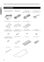
you for purchasing a JVC product. Please read all instructions carefully before operation, to ensure your complete understanding and to obtain the best possible performance from the unit. ACCESSORIES Remote control: RM-RK82 (Cord: 16 ft / 5 m) c 1 Speaker input cord (13 ft / 4 m) c 1 Power cord - JVC CSDA1 | Instructions - Page 7
output of the car stereo. Use L/MONO terminal when the subwoofer output is monaural. PHASE switch LPF (Low Pass Filter) switch POWER/SPEAKER INPUT terminal Switch to the position (a/b) Switches the cutoff frequency. Connects the power cord. which gives you better sound. Remote Controller AUTO - JVC CSDA1 | Instructions - Page 8
equalizer: Set bass to flat • When using the speaker input terminal, connect to a car stereo or power amplifier with output 60W and below for each channel. • When the line output or subwoofer output of the car stereo exceeds 2 V, switch the INPUT ATT. switch to AONB. Maintenance • Use a soft, dry - JVC CSDA1 | Instructions - Page 9
set the switch of the unit in advance. CAUTION This unit is an active subwoofer system. To enjoy this unit safely and comfortably, please take note of the the battery. • When connecting to a car stereo, please also refer to the instruction manual of the car stereo. • This unit generates a strong - JVC CSDA1 | Instructions - Page 10
brackets C. CAUTION If the cushion is not attached to the mounting bracket C, you will hear a scrapping sound when the unit comes into contact with the car body as the car moves and vibrates. 6 - JVC CSDA1 | Instructions - Page 11
• Use the paper pattern to determine the position and mount the unit in the car. 1(218-193m/3m2 )inch Mounting bracket C (c2) assembled in step 2 1-1(2/ the cushion when the back of the unit comes into contact with the car. CAUTION Be sure to check the positions of piping, tanks and electrical - JVC CSDA1 | Instructions - Page 12
item: Thickness 23/32 inch / 18 mm and above) Attaching the remote controller Do not place the remote controller where it will be exposed to direct sunlight. How to use the Clean the item thoroughly before attaching. Power cord Pull Wire clamp Allow the L-shaped pin plug relay to sag slightly - JVC CSDA1 | Instructions - Page 13
receiver, connect to the ACC power. ACC power cord ENGLISH CS-DA1 Crimp connector Power cord Blue/White Remote input TO REMOTE OUT Remote output Left speaker TO SPEAKER INPUT Speaker input White/Black Speaker input cord White 1 Gray 2 White Left speaker JVC Car receiver, etc. Right speaker - JVC CSDA1 | Instructions - Page 14
receiver, connect to the ACC power. ACC power cord L-shaped pin plug relay cord CS-DA1 Crimp connector Power cord Blue/White Remote input TO REMOTE OUT Remote output TO SPEAKER INPUT Speaker input This is not used when LINE IN terminal is used. JVC Car receiver, etc. Pin cord (not supplied - JVC CSDA1 | Instructions - Page 15
power. ACC power cord L-shaped pin plug relay cord CS-DA1 Crimp connector Power cord Blue/White Remote input TO REMOTE OUT Remote output TO SPEAKER INPUT Speaker input This is not used when LINE IN terminal is used. JVC Car receiver, etc. Pin cord (not supplied) Subwoofer output POWER - JVC CSDA1 | Instructions - Page 16
shaped pin plug relay cord CS-DA1 Crimp connector Power cord Blue/White Remote input TO REMOTE OUT Remote output TO SPEAKER INPUT Speaker input This is not used when LINE IN terminal is used. JVC Car receiver, etc. Pin cord (not supplied) 5.1ch subwoofer output POWER LEAD Fuse 15A Yellow - JVC CSDA1 | Instructions - Page 17
terminal and make sure stop lamps and others can operate normally. TROUBLE SHOOTING For more details, consult JVC IN-CAR ENTERTAINMENT car audio dealer. The power is not on. The sound is disrupted. • Connect the remote input and power correctly. • Connect the ground wire correctly to the metal part - JVC CSDA1 | Instructions - Page 18
ENGLISH SPECIFICATIONS Type Speaker Unit Input Terminal Power Output Signal-to-Noise Ratio Active Subwoofer System (Built-in amplifier) 8 inch (20 cm ) Design and specifications are subject to change without notice. DIMENSIONS Main Unit Remote Controller 27/32 (21) 11-1/4 (285) 29/32 - JVC CSDA1 | Instructions - Page 19
FRANÇAIS CONTENU CONTENU 1 ACCESSOIRES 2 AJUSTEMENT DE LA PHASE ET DU SON 3 INSTALLATION 5 CONNEXIONS 9 DÉPANNAGE 13 SPÉCIFICATIONS 14 DIMENSIONS 14 1 - JVC CSDA1 | Instructions - Page 20
pour avoir acheté un produit JVC. Veuillez lire attentivement toutes les instructions avant d'utiliser l'appareil afin de de connexion à broches en L (7-7/8 pouces/200 mm) c 1 Support de fixation A c 1 Support de fixation B c 1 Support de fixation C c 2 Vis de montage Vis de montage Rondelle à - JVC CSDA1 | Instructions - Page 21
ètre à AOFFB. REMOTE CONTROL borne Branchez la POWER/SPEAKER INPUT borne Sert à brancher la cordon d'alimentation. Télécommande Commutateur AUTO BOOST Permet de mettre en et hors service la sortie du caisson de grave. Quand il est en service, le témoin est allumé. EN SERVICE: Bleu, HORS SERVICE - JVC CSDA1 | Instructions - Page 22
é dans les conditions suivantes. • Utilisez la commande de tonalités branchée à l'autoradio lorsqu'il est hors tension. ⅐ Commande Loudness: HORS SERVICE ⅐ BASS: Uniforme ⅐ Égalisateur graphique: Réglez les basses à uniforme • Lorsque vous utilisez la borne d'entrée de l'enceinte, branchez le syst - JVC CSDA1 | Instructions - Page 23
tre très dangereux. Lorsque vous fixez l'unité à un tapis, utilisez les supports de fixation et les vis fournis et serrez de façon appropriée. • N'utilisez branchez à un autoradio, veuillez aussi vous référer au manuel d'instructions de l'autoradio. • Cet appareil émet un champ magnétique puissant - JVC CSDA1 | Instructions - Page 24
5 mm) c 4 Rondelle à ressort (Dia. 7/32 pouce/ M 5 mm) c 4 Tapis etc. 2 Serrez les vis du support de fixation C et placez un coussinet sur le support Support de fixation C 11(21839/3m2mp)ouce Support de fixation C (c2) assemblé à l'étape 2 1 1/(828pomumce) Utilisez un couteau pour percer 4 trous - JVC CSDA1 | Instructions - Page 25
• Utiliser le dessin sur papier pour déterminer la position et installer l'unité dans le véhicule. Tapis etc. 11(21839/3m2mp)ouce Support de fixation C (c2) assemblé à l'étape 2 1 1/(828pomumce) Utilisez un couteau pour percer 4 trous. • Utilisez le dessin sur papier pour établie les positions - JVC CSDA1 | Instructions - Page 26
à une planche vendue en magasin Après l'étape 1, utilisez des vis pour fixer l'unité à la planche achetée en magasin. Dans ce cas, le support de fixation C n'est pas nécessaire. Installation à l'horizontal Installation verticale Vis autotaraudeuse (Dia. 3/16 pouce c 13/16 pouce/ M 4 mm c 20 mm - JVC CSDA1 | Instructions - Page 27
ÇAIS CS-DA1 Raccord à sertir Cordon d'alimentation Bleu/blanc Entrée de la télécommande TO Sortie de télécommande REMOTE OUT (par canal). Gris Gris/noir Enceinte droite Enceinte gauche Autoradio JVC, etc. Enceinte droite POWER LEAD Fusible 15A Jaune ⅐ Branchez à la borne positive + - JVC CSDA1 | Instructions - Page 28
muni d'une sortie de télécommande, connectez à l'alimentation ACC. Cordon d'alimentation ACC CS-DA1 Cordon de connexion à broches en L Raccord à sertir Cordon d'alimentation Bleu/blanc Entrée de la télécommande TO REMOTE OUT Sortie de télécommande TO SPEAKER INPUT Entrée d'enceinte Vous - JVC CSDA1 | Instructions - Page 29
muni d'une sortie de télécommande, connectez à l'alimentation ACC. Cordon d'alimentation ACC CS-DA1 Cordon de connexion à broches en L Raccord à sertir Cordon d'alimentation Bleu/blanc Entrée de la télécommande TO REMOTE OUT Sortie de télécommande TO SPEAKER INPUT Entrée d'enceinte Vous - JVC CSDA1 | Instructions - Page 30
n'est pas muni d'une sortie de télécommande, connectez à l'alimentation ACC. Cordon d'alimentation ACC CS-DA1 Raccord à sertir Cordon d'alimentation Bleu/blanc Entrée de la télécommande TO REMOTE OUT Sortie de télécommande TO SPEAKER INPUT Entrée d'enceinte Vous n'utilisez pas cet élément - JVC CSDA1 | Instructions - Page 31
gative de la batterie et assurez-vous que les feux d'arrêt et les autres feux fonctionnent normalement. DÉPANNAGE Pour obtenir plus de détails, consultez JVC IN-CAR ENTERTAINMENT un revendeur de produits audio pour auto. L'unité n'est pas sous tension. Le son est perturbé. • Branchez l'entrée de la - JVC CSDA1 | Instructions - Page 32
&) Puissance de sortie d'amplifi cateur maximum Fréquence de coupure Courbe de résonance Niveau de pression acoustique Niveau de réglage Exigence d'alimentation Dimensions externes Poids 170 W (85 W a 85 W) CC 14,4 V/Impédance 2 & a 2 & 85 Hz, 110 Hz (Pente de coupure b24 dB/oct. filtre passe-bas - JVC CSDA1 | Instructions - Page 33
ESPAÑOL CONTENIDO CONTENIDO 1 ACCESSORIOS 2 AJUSTES DE FASE Y DE SONIDO 3 INSTALACION 5 CONEXIONES 9 LOCALIZACIÓN DE AVERÍAS 13 ESPECIFICACIONES 14 DIMENSIONES 14 1 - JVC CSDA1 | Instructions - Page 34
Muchas gracias por la compra de un producto JVC. Como primer paso, por favor lea detenidamente este manual para comprender a fondo todas las instrucciones y obtener un máximo disfrute de esta unidad. ACCESSORIOS Control remoto: RM-RK82 (cable: 16 pies / 5 m) c 1 Cable de entrada de - JVC CSDA1 | Instructions - Page 35
Unidad principal Conmutador INPUT ATT. Normalmente, configure esto a AOFFB. REMOTE CONTROL terminal Conecte el mando a distancia. Conmutador AUTO BOOST* Configure el mejor sonido. Conmutador LPF (Filtro de paso bajo) POWER/SPEAKER INPUT terminal Conmuta la frecuencia de corte. Conecta el - JVC CSDA1 | Instructions - Page 36
ESPAÑOL Nota Para prevenir fallos debidos a la entrada excesiva de sonido de tonos bajos y ensordecedores, utilice esta unidad bajo las condiciones siguientes. • Utilice el control de tono para el equipo de coche conectado bajo condiciones planas. ⅐ Control de volumen: APAGADO ⅐ BAJO: Plano ⅐ - JVC CSDA1 | Instructions - Page 37
asegúrese de desconectar el cable de la terminal menos - de la batería. • Al conectar a un equipo de coche, por favor consulte también el manual de instrucciones del equipo de coche. • Esta unidad genera un fuerte campo magnético. No coloque cintas cassette ni tarjetas magnéticas cerca de la - JVC CSDA1 | Instructions - Page 38
Procedimientos para la instalación horizontal 1 Monte los soportes de montaje A y B de la parte trasera de la unidad Soporte de montaje B Tornillo de montaje (Dia. 7/32 pulgadas c 11/32 pulgadas / M 5 mm c 8 mm) c 4 Monte de tal modo que la letra ABB esté en el fondo. Soporte de montaje A Monte - JVC CSDA1 | Instructions - Page 39
Procedimientos para la instalación vertical 1 Monte los soportes de montaje A y B de la parte inferior de la unidad Soporte de montaje B Tornillo de montaje (Dia. 7/32 pulgadas c 11/32 pulgadas / M 5 mm c 8 mm) c 4 Monte de tal modo que la letra ABB esté en el fondo. Soporte de montaje A Monte - JVC CSDA1 | Instructions - Page 40
Montaje sobre tablero disponible comercialmente Después del paso 1, utilice tornillos para asegurar la unidad a un tablero disponible comercialmente. En este caso, el soporte para montaje C no se tiene que utilizar. Instalación horizontal Instalación vertical Tornillo autorroscante (Dia. 3/16 - JVC CSDA1 | Instructions - Page 41
ACC ESPAÑOL CS-DA1 Conector de presión Cable de alimentación Azul/blanco Entrada de control remoto TO REMOTE OUT Salida remota Altavoz vil JVC, etc. Altavoz derecho Conecte a una salida estéreo con una potencia máxima de 60 W o menos (por canal). Gris Gris/negro Altavoz derecho POWER LEAD - JVC CSDA1 | Instructions - Page 42
a la alimentación ACC. Cable de alimentación ACC Cable de relé de clavija de patilla en forma de L CS-DA1 Conector de presión Cable de alimentación Azul/blanco Entrada de control remoto TO REMOTE OUT Salida remota TO SPEAKER INPUT Entrada de altavoz Esto no se utiliza cuando se usa el - JVC CSDA1 | Instructions - Page 43
a la alimentación ACC. Cable de alimentación ACC Cable de relé de clavija de patilla en forma de L CS-DA1 Conector de presión Cable de alimentación Azul/blanco Entrada de control remoto TO REMOTE OUT Salida remota TO SPEAKER INPUT Entrada de altavoz Esto no se utiliza cuando se usa el - JVC CSDA1 | Instructions - Page 44
está equipado con salida para control remoto, conéctelo a la alimentación ACC. Cable de alimentación ACC CS-DA1 Conector de presión Cable de alimentación Azul/blanco Entrada de control TO remoto REMOTE OUT Salida remota TO SPEAKER INPUT Entrada de altavoz Esto no se utiliza cuando se usa - JVC CSDA1 | Instructions - Page 45
que las lámparas de parada y demás funcionen de la manera normal. LOCALIZACIÓN DE AVERÍAS Para mayores detalles, consulte con un concesionario JVC IN-CAR ENTERTAINMENT de sonido para automóvil. El fusible no está desconectado. El sonido se interrumpe. • Conecte la entrada remota y la alimentaci - JVC CSDA1 | Instructions - Page 46
ESPECIFICACIONES Tipo Unidad de altavoz Terminal de entrada Salida de potencia Relación señal a ruido Sistema de realzador de graves activo (Amplificador incorporado) Cono de 8 pulgadas (20 cm) LINE IN (Sistema RCA 1), 0,19 V / 25 k& SPEAKER (1 sistema), 3,7 V / 20 k& 32 W RMS c 2 canales a 2 & y ≤ - JVC CSDA1 | Instructions - Page 47
MEMO - JVC CSDA1 | Instructions - Page 48
EN, FR, SP ᮊ 2007 Victor Company of Japan, Limited 0507SKMSANJEIN ACTIVE SUBWOOFER SYSTEM CS-DA1
-
 1
1 -
 2
2 -
 3
3 -
 4
4 -
 5
5 -
 6
6 -
 7
7 -
8
-
9
-
10
-
11
-
12
-
13
-
14
-
15
-
16
-
17
-
18
-
19
-
20
-
21
-
22
-
23
-
24
-
25
-
26
-
27
-
28
-
29
-
30
-
31
-
32
-
33
-
34
-
35
-
36
-
37
-
38
-
39
-
40
-
41
-
42
-
43
-
44
-
45
-
46
-
47
-
48
 |
 |

INSTRUCTIONS
MANUAL DE INSTRUCCIONES
MANUEL D'INSTRUCTIONS
ACTIVE SUBWOOFER SYSTEM
SYTÈME DE CAISSON DE GRAVE ACTIF
SISTEMA DE SUBWOOFER ACTIVO
CS-DA1
ENGLISH
FRANÇAIS
ESPANÕL
LVT1554-003A
[J]
For Customer Use:
Enter the Model No. and Serial No.
which are located on the top or
bottom of the cabinet. Retain this
information for future reference.
Model No.
Serial No.