JVC DT-V17G15Z Instruction Manual
JVC DT-V17G15Z Manual
 |
View all JVC DT-V17G15Z manuals
Add to My Manuals
Save this manual to your list of manuals |
JVC DT-V17G15Z manual content summary:
- JVC DT-V17G15Z | Instruction Manual - Page 1
MULTI FORMAT LCD MONITOR DT-V17G15Z INSTRUCTIONS For Customer Use: Enter below the Serial No. which is located on the rear of the cabinet. Retain this information for future reference. Model No. : Serial No. : DT-V17G15Z LCT2698-001A - JVC DT-V17G15Z | Instruction Manual - Page 2
. The exclamation point within an equilateral triangle is intended to alert the user to the presence of important operating and maintenance (servicing) instructions in the literature accompanying the appliance. WARNING: TO REDUCE RISK OF FIRE OR ELECTRIC SHOCK, DO NOT EXPOSE THIS APPARATUS TO - JVC DT-V17G15Z | Instruction Manual - Page 3
voltages and other hazards. Refer all service to qualified service personnel. Do not use the product for FCC NOTICE CAUTION: Changes or modifications not approved by JVC could void the user's authority to operate the equipment in accordance with the instruction manual, may cause harmful interference - JVC DT-V17G15Z | Instruction Manual - Page 4
ventilation openings. Install in accordance with the manufacturer's instructions. 8) Do not install near any heat sources such the like. 17) When discarding batteries, environmental problems must be considered and the local rules or laws of JVC KENWOOD Corporation is: JVC Technical Services Europe - JVC DT-V17G15Z | Instruction Manual - Page 5
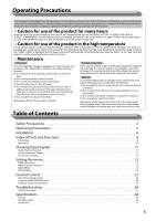
MENU ...14 SET-UP MENU...18 External control 22 About the external control 22 Using the MAKE/TRIGGER System 22 Using the serial communication 24 Troubleshooting 26 Self-check program ...27 Specifications 28 General...28 Available signals ...29 Dimensions...31 5 - JVC DT-V17G15Z | Instruction Manual - Page 6
the stand until it stops. Screw (silver) Approx. 144° Monitor ● To install the stand When attaching the stand to the monitor, insert the guides of the stand plate into the guide holes on the monitor to place the stand in the correct position. Then fix the stand firmly with the attachment screws - JVC DT-V17G15Z | Instruction Manual - Page 7
● To install the monitor on a shelf or any other suitable surface using screws You can install the monitor on a shelf etc. by changing the position of the bottom plate of the stand to a rearward position. CAUTION ● Lay the monitor on a cloth with the LCD panel facing down to prevent the LCD panel - JVC DT-V17G15Z | Instruction Manual - Page 8
Index of Parts and Functions Front panel Tally lamp This lamp is controlled by the tally function of the MAKE/TRIGGER terminal. • You can select the color of the tally lamp from "GREEN" or "RED." (☞ "TALLY SELECT" in "FUNCTION SETTING" on page 18 and "External Control" on page 22) • "NO EFFECT" - JVC DT-V17G15Z | Instruction Manual - Page 9
6 MENU button Activates/deactivates the display of the MAIN MENU (☞ "Menu Operations" on page 13). 7 COLOR OFF button/lamp Displays only the luminance signal. ● This function does not work for RGB input signals. 8 1:1 button/lamp Displays the picture in the original resolution of the input signal. ● - JVC DT-V17G15Z | Instruction Manual - Page 10
to grasp its plug and pull it out. • DO NOT connect the power cord until all connections are complete. • Refer also to the user manual of each piece of equipment. 1 REMOTE terminal Terminal for controlling the monitor by an external control (☞ "External Control" on page 22). 2 VIDEO terminals (BNC - JVC DT-V17G15Z | Instruction Manual - Page 11
Showing Input Signals Audio Channel Selection Select audio channels emitted from the speakers (L/R) and the AUDIO (MONITOR OUT)(OUT1(L)/OUT2(R) terminals, when EMBEDDED AUDIO signals come in to the SDI terminal and SDI input is selected. ● You have to choose a group of selectable audio channels - JVC DT-V17G15Z | Instruction Manual - Page 12
resolution of the signal format. ● Displayed when the 3G SDI signal is input. ● You can set the signal recognition to "AUTO" or one of the manual settings(☞ "SDI FORMAT" on page 21). 4 Setting of "MUTING" ● Displayed only when muting is activated (☞ 4 on page 8). 12 - JVC DT-V17G15Z | Instruction Manual - Page 13
display the MAIN MENU ➔ Press MENU button. To display the SET-UP MENU ➔ Press button while holding button. MAIN MENU Item being selected Operation guide SET-UP MENU 2 Press buttons to select an item, then press button. ● For some items, adjustments will be made by pressing . 3 Press buttons to - JVC DT-V17G15Z | Instruction Manual - Page 14
Setting the menu (cont.) MAIN MENU PICTURE FUNCTION Setting for the picture quality. Item Content Setting value APERTURE *1 Activates/deactivates the function at the level set in "APERTURE LEVEL." OFF, ON APERTURE LEVEL *1 CTI LTI I/P MODE Simultaneously corrects the frequency - JVC DT-V17G15Z | Instruction Manual - Page 15
MARKER*1*2 Settings for marker functions. Item 1/2 AREA MARKER *3 MARKER ASPECT *3 SAFETY MARKER SAFETY AREA FRAME CENTER MARKER LINE BRIGHTNESS 2/2 R-AREA MARKER *3 R-MARKER ASPECT *3 R-SAFETY MARKER R-SAFETY AREA Content Setting value Activate/deactivate the area marker and select the style of - JVC DT-V17G15Z | Instruction Manual - Page 16
Setting the menu (cont.) AUDIO SETTING Settings for the audio output balance, EMBEDDED AUDIO signals and level meter. Item BALANCE E.AUDIO GROUP *1 LEVEL METER SETTING *1 (Configure the following items) Content Setting value Adjust the balance between the right and left speakers. L5 - L1, 0, - JVC DT-V17G15Z | Instruction Manual - Page 17
SCOPE SETTING*1 Configure the settings for the wave form monitor and vector scope. Item GAIN SIZE *2 POSITION *2 Content Adjust the input gain level. Set the window size. Select the window position. TRANSPARENT AUTO OFF WAVE DISPLAY Activates/deactivates the function to make the window - JVC DT-V17G15Z | Instruction Manual - Page 18
Setting the menu (cont.) SET-UP MENU FUNCTION SETTING Configure the sub menu display, the lighting color of the tally lamp, the brightness of the button lamps. Item sub menu POSI. COLOR SYSTEM TALLY SELECT DIMMER COMPONENT PHASE Content Setting value Select the contents and displaying - JVC DT-V17G15Z | Instruction Manual - Page 19
PICTURE SUB ADJ. Configure the standard level of image adjustment. Item CONTRAST *1 BRIGHT *1 CHROMA *1 PHASE *1, *2 NTSC SETUP COMPO. LEVEL sub menu reset Content Setting value Adjust the standard level for the contrast adjusted with the CONTRAST knob on the - 20 - +20 front panel. Adjust the - JVC DT-V17G15Z | Instruction Manual - Page 20
Setting the menu (cont.) REMOTE SETTING (☞ "External Control" on pages 22) Settings for the external control. Item Content Setting value SERIAL TYPE PARALLEL TYPE PIN1 PIN2 PIN3 PIN4 PIN5 PIN6 PIN7 PIN8 Select the input terminal used for external control by serial communication. Select the - JVC DT-V17G15Z | Instruction Manual - Page 21
Normally select "AUTO") ● If the picture is unstable with "AUTO", select the setting value according to the input signal format. ● "M"(meaning "Manual") is displayed on the status display when a setting other than "AUTO" is selected. all reset Restores all the settings and adjustments of the monitor - JVC DT-V17G15Z | Instruction Manual - Page 22
External control About the external control This monitor has three external control terminals. ● MAKE/TRIGGER terminal (RJ-45): The following external control systems are available. 1 MAKE (make contact) system: Controls the monitor by short-circuiting the corresponding pin terminal to the GND pin - JVC DT-V17G15Z | Instruction Manual - Page 23
Display Functions to be controlled TALLY SEL Selects the color of the tally lamp SDI 1 Changes the input to "SDI 1" SDI 2 Changes the input to "SDI 2" DVI Changes the input to "DVI" Display Functions to be controlled COMPONENT Changes - JVC DT-V17G15Z | Instruction Manual - Page 24
External Control (cont.) Using the serial communication You can control the monitor from a personal computer etc. via the RS-485 or RS-232C terminal. ● Consult your dealer for the details of the external control specification. Input terminal RS-485 RS-232C Cable A - JVC DT-V17G15Z | Instruction Manual - Page 25
No. Commands 1 ! * **1 B C N 1 Cr 2 ! * **1 B C N 0 Cr 3 ! * **1 B I D S E T x x*2 Cr 4 ! * **1 B I D R E T Cr 5 ! * **1 B I D D S P x x*2 Cr 6 ! * **1 B I D C H K x x*2 Cr 7 ! * **1 B M E N U Cr 8 ! * **1 B U P Cr 9 ! * **1 B D O W N Cr 10 ! * **1 B A D J R Cr 11 ! * - JVC DT-V17G15Z | Instruction Manual - Page 26
Troubleshooting Solutions to common problems related to the monitor are described here. If none of the solutions presented here solve the problem, unplug the monitor and consult an authorized dealer or service center. Symptom Probable cause and corrective action Page Cannot turn on the unit. No - JVC DT-V17G15Z | Instruction Manual - Page 27
Self-check program This monitor has a self-check function, which allows it to detect malfunctions and alert you. This makes troubleshooting easier. Whenever a problem occurs, one or some of the INPUT SELECT (DVI, COMPO., VIDEO) lamps will flash. If this happens, follow the steps below and contact - JVC DT-V17G15Z | Instruction Manual - Page 28
ratio Compliant video signal format Format Audio output Operation environment Power requirements Rated current External dimensions (excluding protruding parts) Mass Accessories DT-V17G15Z MULTI FORMAT LCD MONITOR Type 17 wide format 16:9 ☞ "Available signals" on page 29 3G SDI DUAL LINK HD SDI - JVC DT-V17G15Z | Instruction Manual - Page 29
is precision equipment and needs dedicated packing material for transportation. Never use any packing material supplied from sources other than JVC or JVC-authorized dealers. ● For easy understanding, pictures and illustrations are emphasized, omitted or composed, and may be slightly different from - JVC DT-V17G15Z | Instruction Manual - Page 30
Specifications (cont.) Computer signals (preset) DVI-D (HDCP) terminals No. Signal name Resolution Horizontal Vertical Frequency Horizontal (kHz) Vertical (Hz) Scan system 1 VGA60 640 480 31.5 59.9 Non-interlace 2 WVGA60 852 480 31.5 59.9 Non-interlace 3 SVGA60 800 600 37.9 - JVC DT-V17G15Z | Instruction Manual - Page 31
Attaching the power cord holder The provided power cord holder prevents accidental disconnection of the AC power cord from the AC IN terminal. The holder consists of two parts: the cord case and the case cover. 1 2 case cover 3 cord case AC IN terminal To take off the case cover ● Do not use - JVC DT-V17G15Z | Instruction Manual - Page 32
© 2012 JVC KENWOOD Corporation LCT2698-001A MULTI FORMAT LCD MONITOR DT-V17G15Z
-
 1
1 -
 2
2 -
 3
3 -
 4
4 -
 5
5 -
 6
6 -
 7
7 -
8
-
9
-
10
-
11
-
12
-
13
-
14
-
15
-
16
-
17
-
18
-
19
-
20
-
21
-
22
-
23
-
24
-
25
-
26
-
27
-
28
-
29
-
30
-
31
-
32
 |
 |

MULTI FORMAT LCD MONITOR
DT-
V17G15Z
INSTRUCTIONS
LCT2698-001A
For Customer Use:
Enter below the Serial No. which is located on the
rear of the cabinet. Retain this information for future
reference.
Model No.
:
DT-V17G15Z
Serial No.
: