JVC DTV24L1U Operator manual for DT-V24L1/D, DT-V20L1/D (20 pages)
JVC DTV24L1U - MultiFormat LCD Monitor Manual
 |
UPC - 046838028472
View all JVC DTV24L1U manuals
Add to My Manuals
Save this manual to your list of manuals |
JVC DTV24L1U manual content summary:
- JVC DTV24L1U | Operator manual for DT-V24L1/D, DT-V20L1/D (20 pages) - Page 1
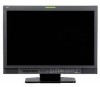
DT-V24L1D DT-V24L1 DT-V20L1D DT-V20L1 MULTI FORMAT LCD MONITOR The illustration of the monitor is of DT-V24L1D. INSTRUCTIONS Table of Contents Safety Precautions 2 IMPORTANT SAFEGUARDS 2 Maintenance 3 Installation 4 Using the monitor on the stand 4 Installing the monitor in the rack 5 Daily - JVC DTV24L1U | Operator manual for DT-V24L1/D, DT-V20L1/D (20 pages) - Page 2
modifications not approved by JVC could void the user's the instruction manual, outlet. 3. Refer service to qualified service personnel. a) When supply for the product is controlled by inserting or removing the power dangerous voltage points or short-circuit the parts, which could result in a fire - JVC DTV24L1U | Operator manual for DT-V24L1/D, DT-V20L1/D (20 pages) - Page 3
parts are required, be sure the service technician has used replacement parts product, please visit our web page www.jvc-europe.com to obtain information about the • Controlled EMC 485 cable (twist pair cable) (A straight LAN cable) REMOTE cable (twist pair cable) (A straight LAN cable) Length - JVC DTV24L1U | Operator manual for DT-V24L1/D, DT-V20L1/D (20 pages) - Page 4
you cannot tilt the monitor downward. The illustrations of the monitor are of DT-V24L1D. CAUTION • When lifting up the stand, lay the monitor on a cloth with the LCD panel facing down to prevent the LCD panel being damaged. • Be careful not to pinch your fingers in the moving parts. • Make sure to - JVC DTV24L1U | Operator manual for DT-V24L1/D, DT-V20L1/D (20 pages) - Page 5
higher position Screw holes for lower position 7 Installing the monitor in the rack (DT-V20L1D and DT-V20L1 only) Use a JVC's RACK MOUNT ADAPTER (RK-C20L1; not supplied). CAUTION The illustration of the monitor is of DT-V24L1D. Screw holes (See page 18 for the specifications of the screw holes.) - JVC DTV24L1U | Operator manual for DT-V24L1/D, DT-V20L1/D (20 pages) - Page 6
page 12 and "External Control" on page 14). NOTE "NO EFFECT" is displayed when you press a button which is not available for the current input or signal format (the lamp lights even when the function does not actually work). The illustration of the monitor is of DT-V24L1D. 1 Speakers (stereo) The - JVC DTV24L1U | Operator manual for DT-V24L1/D, DT-V20L1/D (20 pages) - Page 7
guide When the set-up menu is displayed Selected item Operation guide DT-V24L1D and DT-V20L1D only) Select audio channels of EMBEDDED AUDIO signals to output from the speakers (L/R) and MONITOR OFF" (☞ "AUDIO SETTING" on page 11). 2 Signal format • "NO SYNC" is displayed when no video signal is - JVC DTV24L1U | Operator manual for DT-V24L1/D, DT-V20L1/D (20 pages) - Page 8
/TRIG.) terminal (RJ-45) Terminal for controlling the monitor by an external control. ☞ "External Control" on page 14 2 REMOTE (RS-485) terminals (RJ-45) Terminals for controlling the monitor by an external control. ☞ "External Control" on page 14 3 REMOTE (RS-232C) terminal (D-sub 9-pin) Terminal - JVC DTV24L1U | Operator manual for DT-V24L1/D, DT-V20L1/D (20 pages) - Page 9
/60i 16 1035/60i 17 1080/50i 18 1080/60p 19 1080/50p 20 1080/30p 21 1080/25p 22 1080/24p 23 1080/30psF 24 1080/24psF VIDEO (INPUT1, INPUT2) Input terminal COMPO./RGB (Analog component/ analog RGB) HD/SD SDI (IN 1, IN 2)*1 (DT-V24L1D and DT-V20L1D only - JVC DTV24L1U | Operator manual for DT-V24L1/D, DT-V20L1/D (20 pages) - Page 10
guide LCD of the monitor is Control" on page 14). • When a picture is displayed in 4:3 aspect ratio, SAFETY AREA for the 4:3 area is displayed. • To display SAFETY AREA for the area of a picture displayed in 16:9 aspect ratio, set "MARKER SELECT" and "R-MARKER SELECT" to "OFF." *1 DT-V24L1D and DT - JVC DTV24L1U | Operator manual for DT-V24L1/D, DT-V20L1/D (20 pages) - Page 11
guide ASSIGN (IN 1) terminal is assigned to. SDI-1*1, SDI-2*1, DVI, COMP/RGB, VIDEO-1, VIDEO-2 and 7 - 12 at the top right.), 13:24 (Displays the odd channels at the top left bar is displayed at the lower part of the screen. • You cannot DT-V24L1D and DT-V20L1D only *2 Memorized for each input. 11 - JVC DTV24L1U | Operator manual for DT-V24L1/D, DT-V20L1/D (20 pages) - Page 12
operation procedure, see page 7. Operation guide Shows the buttons for each operation. ., 8sec. NOTE The tally lamp is controlled using MAKE/TRIG. terminal of REMOTE terminals (☞ "External Control" on page 14). PICTURE SUB ADJ. signal format. *3 Memorized for each color temperature (HIGH, LOW, - JVC DTV24L1U | Operator manual for DT-V24L1/D, DT-V20L1/D (20 pages) - Page 13
guide REMOTE SETTING (☞ "External Control" on pages 14 and 15) Setting for the external control Choose if the CRC error indication for the input HD SDI signal is displayed on the screen (☞ "About the reset," the monitor is turned off then turned on automatically. *1 DT-V24L1D and DT-V20L1D only *2 - JVC DTV24L1U | Operator manual for DT-V24L1/D, DT-V20L1/D (20 pages) - Page 14
Controls the monitor with RS-485 system. (☞ "Using the serial communication" on page 15) Set the following items of "REMOTE SETTING" in set-up menu according to the external control terminal and control system you use (☞ page 13). Control *4 DT-V24L1D and DT-V20L1D only *5 Must be controlled with - JVC DTV24L1U | Operator manual for DT-V24L1/D, DT-V20L1/D (20 pages) - Page 15
REMOTE SETTING" to "MAKE" or "TRIGGER" in the set-up menu. 2 Short-circuit the 7th pin terminal (external control) to the 8th pin terminal (GND) so that the monitor can be controlled by the external control the monitor is off (standby). *2 These commands are available for only DT-V24L1D and DT-V20L1D - JVC DTV24L1U | Operator manual for DT-V24L1/D, DT-V20L1/D (20 pages) - Page 16
and alert you. This makes troubleshooting easier. Whenever a problem occurs, one or some of the INPUT SELECT lamps will flash. If this happens, follow the steps below and contact your dealer to resolve the problem. The illustration of the monitor is of DT-V24L1D. 1 Check which lamps are flashing - JVC DTV24L1U | Operator manual for DT-V24L1/D, DT-V20L1/D (20 pages) - Page 17
DT-V24L1D/DT-V24L1 DT-V20L1D/DT-V20L1 Type Multi format LCD monitor Screen size Type 24 wide format Type 20 wide format Aspect ratio 16:10 LCD panel 24 A (AC 120 V)/0.60 A (AC 220 - 240 V) External dimensions (excluding protruding parts) Width : 564 mm (22 1/4˝) 564 mm (22 1/4˝) Height - JVC DTV24L1U | Operator manual for DT-V24L1/D, DT-V20L1/D (20 pages) - Page 18
Specifications (cont.) 7 Dimensions Unit: mm (inch) DT-V24L1D/DT-V24L1 564 (22 1/4) 99 16) 99 (4) 52.7 (2 1/8) 1.5 (1/16) The illustrations of the monitor are of DT-V24L1D. 100 VESA mounting holes (Size: M4, depth: 10 mm) 100 - JVC DTV24L1U | Operator manual for DT-V24L1/D, DT-V20L1/D (20 pages) - Page 19
- JVC DTV24L1U | Operator manual for DT-V24L1/D, DT-V20L1/D (20 pages) - Page 20
DT-V24L1D/DT-V24L1/DT-V20L1D/DT-V20L1 MULTI FORMAT LCD MONITOR © 2006 Victor Company of Japan, Limited 1106MKH-MW-VP
-
 1
1 -
 2
2 -
 3
3 -
 4
4 -
 5
5 -
 6
6 -
 7
7 -
8
-
9
-
10
-
11
-
12
-
13
-
14
-
15
-
16
-
17
-
18
-
19
-
20
 |
 |

INSTRUCTIONS
DT-V24L1D
DT-V24L1
DT-V20L1D
DT-V20L1
MULTI FORMAT LCD MONITOR
Table of Contents
Safety Precautions
..............................................
2
IMPORTANT SAFEGUARDS
...........................
2
Maintenance
.....................................................
3
Installation
............................................................
4
Using the monitor on the stand
........................
4
Installing the monitor in the rack
.......................
5
Daily Operations / Connections
.........................
6
Front panel
.......................................................
6
Rear panel
........................................................
8
Available signals
...............................................
9
Menu Configuration—MAIN MENU
..................
10
Menu Configuration—SET-UP MENU
...............
12
External Control
.................................................
14
About the external control
..............................
14
Using the MAKE/TRIGGER system
.................
14
Using the serial communication
.....................
15
Troubleshooting
.................................................
16
Self-check program
........................................
16
Specifications
....................................................
17
General
...........................................................
17
Input/output terminals
.....................................
17
Dimensions
.....................................................
18
The illustration of the monitor is of DT-V24L1D.
LCT2202-001A