JVC GD-V4200PZW GD-V4200PZW plasma display 32 page instruction manual (English
JVC GD-V4200PZW - Plasma Display Manual
 |
View all JVC GD-V4200PZW manuals
Add to My Manuals
Save this manual to your list of manuals |
JVC GD-V4200PZW manual content summary:
- JVC GD-V4200PZW | GD-V4200PZW plasma display 32 page instruction manual (English - Page 1
ENGLISH INSTRUCTIONS Model GD-V4200PZW GD-V4200PZW-G GD-V4200PCE GD-V4200PCE-G Thank you for purchasing this JVC Monitor. Before using the monitor, read this manual carefully so that you know how to use the Monitor correctly. Refer to this manual whenever questions or problems about operation - JVC GD-V4200PZW | GD-V4200PZW plasma display 32 page instruction manual (English - Page 2
for help. Caution: Changes or modifications not approved by JVC could void the user's authority to operate the equipment. IMPORTANT INFORMATION WARNING: TO use and service. Please read these "Important Safeguards" carefully before use. - All the safety and operating instructions should be read - JVC GD-V4200PZW | GD-V4200PZW plasma display 32 page instruction manual (English - Page 3
service personnel under the following conditions: a) When the power supply cord or plug is damaged. b) If liquid has been spilled, or objects have fallen on the product. c) If the product has been exposed to rain or water. d) If the product operated normally by following the operating instructions - JVC GD-V4200PZW | GD-V4200PZW plasma display 32 page instruction manual (English - Page 4
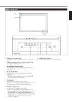
aspect ratio changes as follows: REGULAR FULL PANORAMIC ZOOM 9 POWER button (page 12) Use this button to turn on/off the power. p VOLUME + / - buttons (page 12) Use these buttons to adjust the volume level. • Only for GD-V4200PCE and GD-V4200PCE-G: Though you can use these buttons, sound will - JVC GD-V4200PZW | GD-V4200PZW plasma display 32 page instruction manual (English - Page 5
here. When the Monitor is turned on, the power lamp glows green. It glows red in standby mode. 6 POWER button (page 12) Use this button to turn (page 12) Use this button to switch between inputs. • Only for GD-V4200PCE and GD-V4200PCE-G: Only RGB input can be reproduced. Though you can switch to - JVC GD-V4200PZW | GD-V4200PZW plasma display 32 page instruction manual (English - Page 6
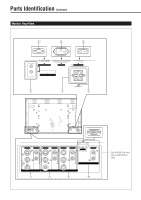
) REMOTE CONTROL 4 5 I MAIN POWER SPEAKER OUT R L INTERNAL EXTERNAL 6 VIDEO AUDIO VIDEO AUDIO Y/C Y/C IN IN R R L/MONO OUT L/MONO OUT VIDEO A VIDEO B 7 8 VIDEO AUDIO Y PB / B-Y R L/MONO PR / R-Y COMPONENT 9 AUDIO PC L/MONO R RGB p GD-V4200PZW and GD-V4200PZW-G only 6 - JVC GD-V4200PZW | GD-V4200PZW plasma display 32 page instruction manual (English - Page 7
terminal, consult an authorized JVC dealer. 2 AC INPUT terminal (page 11) Connect the supplied power cord to this terminal. 3 MAIN POWER switch (page 12) to the audio output terminals of a personal computer. Note: * GD-V4200PCE and GD-V4200PCE-G do not have the following input terminals - VIDEO A, - JVC GD-V4200PZW | GD-V4200PZW plasma display 32 page instruction manual (English - Page 8
Monitor. • Remote control (RM-C575) x 1 • Remote control cable x 1 • Power cord (approx. 2.5 m) x 3 (Use the one matching the wall outlet.) • or try recharging them. • The service life of batteries is six months to one year for normal use. The supplied batteries are only for checking the operation - JVC GD-V4200PZW | GD-V4200PZW plasma display 32 page instruction manual (English - Page 9
refer also to the user manual for each option to use. Do not tilt the Monitor rightward, leftward, or backward. • Route the power cord and connection cables lead to personal injury. For detailed information, refer to the manual supplied for the stand. When mounting the Monitor on the wall Front - JVC GD-V4200PZW | GD-V4200PZW plasma display 32 page instruction manual (English - Page 10
it out. • Connect the power cord after having finished all other connections. • Refer also to the user manual of each piece of equipment. XGA-60 11 XGA-70 12 RGB15K-60 13 RGB15K-50 - User-defined - User-defined Screen resolution Horizontal Vertical 640 400 640 400 640 480 640 480 640 480 - JVC GD-V4200PZW | GD-V4200PZW plasma display 32 page instruction manual (English - Page 11
R-Y COMPONENT AUDIO PC L/MONO R RGB These terminals are not available for GD-V4200PCE and GD-V4200PCE-G. To use them, you need to install video interface kit (IF- B terminal can be used as the video input terminal. Power cord ( supplied) To a wall outlet External Speakers MENU/EXIT RM-C575 - JVC GD-V4200PZW | GD-V4200PZW plasma display 32 page instruction manual (English - Page 12
panel glows red. 2 Turn on the power. Press POWER on the remote control to turn the power on. The POWER lamp changes to glow green. 3 Select an input. Select the desired input by pressing VIDEO A, VIDEO B, COMPO. or RGB. • Only for GD-V4200PCE and GD-V4200PCE-G: Only RGB image is reproduced though - JVC GD-V4200PZW | GD-V4200PZW plasma display 32 page instruction manual (English - Page 13
ENGLISH Changing the Aspect Ratio ASPECT DISPLAY ASPECT POWER VIDEO A VIDEO B COMPO. RGB MUTING VOLUME MULTIPLE MONITOR ADJUSTMENT MODE ID SET ID MENU/EXIT RM-C575 REMOTE CONTROL UNIT With this Monitor, you can - JVC GD-V4200PZW | GD-V4200PZW plasma display 32 page instruction manual (English - Page 14
remote control or on Monitor for menu operations. • Refer also to "Menu Classifications" on pages 26 and 27. 2 / 3 MENU/EXIT MENU INPUT POWER MENU INPUT POWER 5 / MENU Adjusting the Screen Size and Position (For RGB input only) While RGB input is selected, the screen size and position can be - JVC GD-V4200PZW | GD-V4200PZW plasma display 32 page instruction manual (English - Page 15
ENGLISH 5 Press 2/3 to adjust the selected item. 6 Press MENU/EXIT (or MENU on the Monitor) twice to exit from the menu operations. To make an adjustment while viewing the adjustment bar After step 3 on page 14, proceed as follows: 1 Press 5/∞ to move the cursor (3) to "sub menu." 2 Press 3 to - JVC GD-V4200PZW | GD-V4200PZW plasma display 32 page instruction manual (English - Page 16
Video Adjustments (Continued) 2 / 3 VOLUME - MENU/EXIT 5 5 MENU INPUT POWER MENU INPUT POWER 5 / MENU DISPLAY ASPECT POWER VIDEO A VIDEO B COMPO. RGB MUTING VOLUME MULTIPLE MONITOR ADJUSTMENT MODE ID SET ID MENU/EXIT RM-C575 REMOTE CONTROL UNIT 2 / 3 5 / To make an adjustment - JVC GD-V4200PZW | GD-V4200PZW plasma display 32 page instruction manual (English - Page 17
holding VOLUME - to display the Setup Menu. On the Monitor: Press MENU while holding 2 to display the Setup Menu. Cursor (3) SET-UP MENU POWER SAVE : 1MIN. CONTROL LOCK : ON STATUS DISPLAY : ON SCREEN SAVER : ON WHITE BACK : ON VENTILATION MODE : H WHITE BALANCE all reset HOUR METER - JVC GD-V4200PZW | GD-V4200PZW plasma display 32 page instruction manual (English - Page 18
SELECT." 3 Press 3 to display the Function Selection Menu. FUNCTION SELECT COLOR TEMP. ASPECT SIGNAL MODE reset : HIGH* : PANORAMA : AUTO 5 5 DISPLAY ASPECT POWER VIDEO A VIDEO B COMPO. RGB MUTING VOLUME MULTIPLE MONITOR ADJUSTMENT MODE ID SET ID MENU/EXIT RM-C575 REMOTE CONTROL UNIT - JVC GD-V4200PZW | GD-V4200PZW plasma display 32 page instruction manual (English - Page 19
ENGLISH Setting the Receivable Signal Types You can set the receivable signal types. Normally, select "AUTO." A common setting will apply to both VIDEO A and B terminals, and a different setting will apply to the COMPONENT terminal. 1 Press MENU/EXIT (or MENU on the Monitor) to display the Main - JVC GD-V4200PZW | GD-V4200PZW plasma display 32 page instruction manual (English - Page 20
on the remote control or on Monitor for menu operations. • Refer also to "Menu Classifications" on pages 26 and 27. MENU INPUT POWER MENU INPUT POWER 2 / 3 5 / MENU Showing On-screen Display The input mode and signal type will be indicated on the screen. • The following procedure can be - JVC GD-V4200PZW | GD-V4200PZW plasma display 32 page instruction manual (English - Page 21
This may be necessary when you ask for any service. 1 On the remote control: Press MENU/EXIT display the Setup Menu. Cursor (3) SET-UP MENU POWER SAVE : 1MIN. CONTROL LOCK : ON STATUS DISPLAY after the signal has ceased to be supplied. Each time you press the button, the amount of time changes - JVC GD-V4200PZW | GD-V4200PZW plasma display 32 page instruction manual (English - Page 22
holding VOLUME - to display the Setup Menu. On the Monitor: Press MENU while holding 2 to display the Setup Menu. Cursor (3) SET-UP MENU POWER SAVE : 1MIN. CONTROL LOCK : ON STATUS DISPLAY : ON SCREEN SAVER : ON WHITE BACK : ON VENTILATION MODE : H WHITE BALANCE all reset HOUR METER - JVC GD-V4200PZW | GD-V4200PZW plasma display 32 page instruction manual (English - Page 23
) twice to exit from the menu operations. Resetting All the Setup Menu Settings You can reset all the following Setup Menu settings at a time. • Power Saving function (see page 21) • Control Lock function (see page 21) • Status Display function (see page 22) • Screen Saver function (see the left - JVC GD-V4200PZW | GD-V4200PZW plasma display 32 page instruction manual (English - Page 24
CONTROL UNIT Remote control ID MODE ID SET MULTIPLE MONITOR ADJUSTMENT VOLUME MUTING VIDEO A VIDEO B COMPO. RGB POWER DISPLAY ASPECT Remote control cable (supplied) Monitor 1 (Master) Monitor 2 (Slave) Monitor 3 (Slave) Monitor XX (Slave) RS232C CONTROL IN AC INPUT (100V) OUT WIRED - JVC GD-V4200PZW | GD-V4200PZW plasma display 32 page instruction manual (English - Page 25
ENGLISH Operating the Monitors Simultaneously • Check that no ID number is shown on the screens. If any ID numbers are shown, press MODE to erase them. • The following procedure should be performed slowly and securely. Example: When adjusting "CONTRAST": 1 Press MENU/EXIT to display the Main Menu. - JVC GD-V4200PZW | GD-V4200PZW plasma display 32 page instruction manual (English - Page 26
Menu Classifications Main Menu Main Menu MAIN MENU SIZE/POSITION ADJ. PICTURE ADJ. FUNCTION SELECT STATUS DISPLAY ENTER: SELECT: EXIT: MENU Size/Position Adjustment Menu SIZE/POSITION ADJ. H SIZE H POSITION V SIZE V POSITION CLOCK PHASE sub menu reset : +01 : 00 : -02 : 00 : 00 ADJUST: SELECT: - JVC GD-V4200PZW | GD-V4200PZW plasma display 32 page instruction manual (English - Page 27
Are you sure? "YES" then press key. "NO" then press MENU key POWER SAVE CONTROL LOCK STATUS DISPLAY SCREEN SAVER WHITE BACK VENTILATION MODE WHITE BALANCE all reset mode is automatically assumed after the input signal has stopped being supplied. (See page 21.) Sets the Monitor so that it cannot - JVC GD-V4200PZW | GD-V4200PZW plasma display 32 page instruction manual (English - Page 28
Troubleshooting Solutions to common problems related to the Monitor are described here. If none of the solutions presented here solves the problem, unplug the Monitor and consult an authorized dealer or service center. Symptom Probable cause Corrective action Power is not supplied. • Is the - JVC GD-V4200PZW | GD-V4200PZW plasma display 32 page instruction manual (English - Page 29
after recovering from a brief power interruption), the self-diagnostic lamps Plasma Display Monitor GD-V4200PZW/GD-V4200PZW-G GD-V4200PCE/GD-V4200PCE-G Self-diagnostic Report Sheet The self-diagnostic lamps light or flash as listed on the following table. Please give me immediate advice or service - JVC GD-V4200PZW | GD-V4200PZW plasma display 32 page instruction manual (English - Page 30
Specifications General: Model name Frame colour Screen size Aspect ratio Mass External dimensions Power requirements Rated input current Effective screen size Number of pixels displayed Number of colors displayed Compatible systems Audio output Speakers Operating conditions GD-V4200PZW/GD-V4200PZW - JVC GD-V4200PZW | GD-V4200PZW plasma display 32 page instruction manual (English - Page 31
ENGLISH Pin assignment (Specifications for terminals) • Y/C terminal 4 3 2 1 • RS-232C terminal 9 8 7 6 Note: 5 • This is a female type 4 3 connector. 2 1 Pin number 1 57.5 (2 3/8) 570 (221/2) 640 (251/4) 577 (22 3/4) 518.4 (201/2) MENU INPUT POWER Unit: mm (inch) 1 7 (11/16) 31 - JVC GD-V4200PZW | GD-V4200PZW plasma display 32 page instruction manual (English - Page 32
32
-
 1
1 -
 2
2 -
 3
3 -
 4
4 -
 5
5 -
 6
6 -
 7
7 -
8
-
9
-
10
-
11
-
12
-
13
-
14
-
15
-
16
-
17
-
18
-
19
-
20
-
21
-
22
-
23
-
24
-
25
-
26
-
27
-
28
-
29
-
30
-
31
-
32
 |
 |

1
ENGLISH
INSTRUCTIONS
Model
GD-V4200PZW
GD-V4200PZW-G
GD-V4200PCE
GD-V4200PCE-G
Page
Safety Precautions
....................................................
2
Parts Identification
.....................................................
4
•
Remote Control
...................................................
4
•
Monitor: Front View
.............................................
5
•
Monitor: Rear View
..............................................
6
Preparations
..............................................................
8
•
Checking the Accessories
...................................
8
•
Installing the Batteries
.........................................
8
Installation
.................................................................
9
• Precautions
.........................................................
9
Connections
............................................................
10
• Precautions
.......................................................
10
•
Available Signals
...............................................
10
•
Connection Examples
.......................................
11
Basic Operations
.....................................................
12
•
Daily Operations
................................................
12
•
Changing the Aspect Ratio
...............................
13
Video Adjustments
..................................................
14
•
Adjusting the Screen Size and Position
(For RGB input only)
.........................................
14
•
Adjusting the Picture Quality
............................
15
•
Adjusting the Color Temperature
......................
16
•
Adjusting the White Balance
.............................
17
•
Changing the Aspect Ratio
...............................
18
•
Setting the Receivable Signal Types
................
19
•
Resetting the Function Selection Menu Settings ..
19
Page
Other Convenient Functions
....................................
20
•
Showing On-screen Display
.............................
20
•
Confirming the Use Time
...................................
21
•
Setting the Power Saving Function
..................
21
•
Prohibiting the Monitor’s Button Operations
.....
21
•
Reducing the Afterimage Effect
........................
22
•
Showing the On-screen When Changing
the Input Mode
..................................................
22
•
Using the Screen Saver Function
.....................
23
•
Mounting the Monitor Vertically
........................
23
•
Resetting All the Setup Menu Settings
.............
23
Serial Connections and Operations
........................
24
•
Connecting the Remote Control Cables
...........
24
•
Assigning ID Numbers
.......................................
24
•
Operating the Monitors Simultaneously
............
25
•
Operating the Monitors Individually
..................
25
Menu Classifications
...............................................
26
•
Main Menu
........................................................
26
•
Setup Menu
.......................................................
27
Troubleshooting
.......................................................
28
•
Self-diagnostic Indication
..................................
29
Specifications
..........................................................
30
Contents
This instruction manual refers to the GD-V4200PZW, GD-V4200PZW-G, GD-V4200PCE and GD-V4200PCE-G. The explanations
and illustrations used in this instruction manual are of the GD-V4200PZW unless otherwise stated.
The differences between each model are as follows:
GD-V4200PZW
Silver
Frame Colour
Inputs
VIDEO A
VIDEO B
COMPONENT
RGB AUDIO
GD-V4200PZW-G
Gray
GD-V4200PCE
Silver
GD-V4200PCE-G
Gray
Available
Available
Available
Available
Not available*
1
Not available*
1
Not available*
1
Not available*
1
*
1
These inputs will be available with the separately-purchased video interface kit (IF-C420P1W). Ask your
dealer to install the video interface kit.
Thank you for purchasing this JVC Monitor.
Before using the monitor, read this manual carefully so
that you know how to use the Monitor correctly.
Refer to this manual whenever questions or problems
about operation arise. Be sure to read and observe the
safety precautions.
Keep this manual where the user can see it easily.
*
Installation and removal require special expertise.
Consult your product dealer for details.