JVC GD-V502U Instruction Manual
JVC GD-V502U - Plasma Display Monitor Manual
 |
View all JVC GD-V502U manuals
Add to My Manuals
Save this manual to your list of manuals |
JVC GD-V502U manual content summary:
- JVC GD-V502U | Instruction Manual - Page 1
PLASMA DISPLAY MONITOR GD-V422U GD-V502U INSTRUCTIONS For customer Use: Enter below the Model No. and the Serial No. which is located on the rear panel of the cabinet. Retain this information for future reference. Model No. Serial No. - JVC GD-V502U | Instruction Manual - Page 2
to tell the user that important operating and servicing instructions are in the papers with the appliance. serviceable parts inside. Refer servicing to qualified service personnel. 2) Do not remove the grounding pin on the power plug. This apparatus is equipped with a three pin grounding-type power - JVC GD-V502U | Instruction Manual - Page 3
provided or the manufacturer's instructions have been adhered to. ) Use only with the cart, stand, tripod, bracket, or table specified power-line surges. 14) Refer all servicing to qualified service personnel. Servicing is required when the apparatus has been damaged in any way, such as power-supply - JVC GD-V502U | Instruction Manual - Page 4
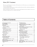
Customer Welcome to the JVC family of customers. We hope that you will have many years of enjoyment from your new Plasma Display. To obtain maximum benefit from your set, please read these Instructions before making any adjustments, and retain them for future reference. Retain your purchase receipt - JVC GD-V502U | Instruction Manual - Page 5
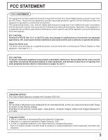
used in accordance with the instruction manual, may cause harmful interference JVC could cause harmful interference and would void the user's authority to operate this device. Attach the ferrite core: The ferrite cores provided as a supplied accessory must be used when connecting this Plasma Display - JVC GD-V502U | Instruction Manual - Page 6
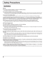
product. AC Power Supply Cord The Plasma Display is designed to operate on 120 V AC, 50/60 Hz. Securely insert the power cord plug as Service Center. If the Plasma Display will not be used for a long period of time, unplug the power cord from the wall outlet. If problems occur during use If a problem - JVC GD-V502U | Instruction Manual - Page 7
by JVC) • Speakers TS-C422SPG (GD-V422U) TS-C5001SPG (GD-V502U) • Stand Unit TS-C50P5G • Wall Mounting Unit TS-C50P6G • Wall Mounting Unit (angled TS-C50P2G • Ceiling Suspension Unit TS-C50P3G Always be sure to ask a qualified technician to carry out set-up. When using the Plasma Display Do - JVC GD-V502U | Instruction Manual - Page 8
Supplied Check that you have the Accessories and items shown Operating Instruction book GD-V422U GD-V502U Remote Control Transmitter EUR646532 INPUT SURROUND VOL N R PICTURE SOUND SET UP MULTI ZOOM PIP SWAP SELECT MOVE PICTURE POS. /SIZE ASPECT PC OFF TIMER PLASMA DISPLAY - JVC GD-V502U | Instruction Manual - Page 9
to the speaker's Installation Manual for details on speaker installation. (Example: GD-V422U) Speakers (Optional cables to minimize stress (especially in the power cord), firmly bind all cables with the supplied fixing band. To tighten: To loosen: Plasma Display with the Stand Unit. 9 - JVC GD-V502U | Instruction Manual - Page 10
, the image will not be displayed properly if the signals exceed 1,200 lines.) (2) The display resolution is a maximum of 768 × 768 dots (GD-V422U), 1,024 × 768 dots (GD-V502U) when the aspect mode is set to "4:3", and 1,024 × 768 dots (GD-V422U), 1,366 × 768 dots (GD-V502U) when the aspect mode is - JVC GD-V502U | Instruction Manual - Page 11
to the Plasma Display. (2) The computer shown is for example purposes only. (3) Additional equipment and cables shown are not supplied with this None SL1 SL2 SL3 PC1 None NORM ZOOM FULL JUST SELF Control details Power ON Power OFF Volume 00 - 63 Audio MUTE OFF Audio MUTE ON Input select - JVC GD-V502U | Instruction Manual - Page 12
(1) Change the "Component / RGB-in" setting in the "Setup" menu to "Component". (see page 33) (2) Additional equipment, cables and adapter plugs shown are not supplied with this set. RGB signal (R, G, B, HD, VD) Computer RGB Camcorder or VIDEO IN VIDEO OUT R AUDIO L VD HD PR/CR/R PB/CB/B Y/G AV - JVC GD-V502U | Instruction Manual - Page 13
control to turn the Plasma Display off. Power Indicator: Red (STAND-BY) Press the button on the remote control to turn the Plasma Display on. Power Indicator: Green Turn the power to the Plasma Display off by pressing the Main power switch on the Plasma Display, when the Plasma Display is on or in - JVC GD-V502U | Instruction Manual - Page 14
Viewing PICTURE SET UP is still inserted into the wall outlet.) • Stand-by .... Red • Power-ON ..... Green • DPMS Orange [With PC input signal and during Up "+" Down "-" Plasma C.A.T.S (Contrast Automatic Tracking System) When the menu screen is displayed. Plasma C.A.T.S automatically senses the - JVC GD-V502U | Instruction Manual - Page 15
Basic Controls Stand-by (ON / OFF) button The Plasma Display must first be plugged into the wall outlet and turned on at the power switch (see page 13). Press this button to turn the Plasma Display On, from Standby mode. Press it again to turn the Plasma Display Off to Standby mode. SURROUND button - JVC GD-V502U | Instruction Manual - Page 16
UP MULTI ZOOM PIP SWAP SELECT MOVE PICTURE POS. /SIZE ASPECT PC OFF TIMER PLASMA DISPLAY To PICTURE POS./ SIZE adjust menu (see page 20) During "VIDEO (S POWER SAVE OFF STANDBY SAVE ON POWER MANAGEMENT OFF OSD LANGUAGE ENGLISH (US) SET UP 2/2 AUTO POWER OFF OFF MULTI DISPLAY - JVC GD-V502U | Instruction Manual - Page 17
BRIGHT To setup MULTIDISPLAY screen. (See page 31) MULTI DISPLAY SETUP MULTI DISPLAY SETUP ON ARRANGEMENT 2 2 LOCATION A1 Press to select UP TIMER PRESENT TIME OF DAY 2 : 30 POWER ON FUNCTION OFF POWER ON TIME 0 : 00 POWER OFF FUNCTION OFF POWER OFF TIME 0 : 00 To PRESENT TIME SET - JVC GD-V502U | Instruction Manual - Page 18
button to select the input signal to be played back from the equipment which has been connected to the Plasma Display. Input signals will change as follows: R - STANDBY G POWER ON - + INPUT MENU VOL ENTER INPUT MENU + VOL ENTER INPUT1 INPUT2 INPUT3 PC IN INPUT SURROUND VOL N R Notes - JVC GD-V502U | Instruction Manual - Page 19
MULTI PIP Operations] NORMAL 16 : 9 (1) Picture and Picture, Picture in Picture : (2) Others : Aspect switching is not possible. PC OFF TIMER PLASMA DISPLAY Notes: (1) For PC signal input, the mode switches between "NORMAL", "ZOOM" and "FULL" only. (2) For a 1125 (1080) / 60i · 50i · 24p - JVC GD-V502U | Instruction Manual - Page 20
to adjust POS./ SIZE. R Press to exit from adjust mode. When the Position Left " " button is pressed. PC OFF TIMER PLASMA DISPLAY Notes: (1) Adjustment details are memorized separately for different input signal formats (Adjustments for component signals are memorized for 525 (480) / 60i - JVC GD-V502U | Instruction Manual - Page 21
mode (STANDARD, AUTO). Helpful Hint ( N / NORMALIZE Normalization) While the "SOUND" menu is displayed, if either the N button on the remote control is pressed at any time or the (ACTION again to reactivate sound. Sound is also reactivated when power is turned off or volume level is changed. 21 - JVC GD-V502U | Instruction Manual - Page 22
page) Press the left or right button to switch between modes. NORMAL COOL WARM Helpful Hint ( N / NORMALIZE Normalization) While the "PICTURE" menu is displayed, if either the N button on the remote control is pressed at any time or the (ACTION button) is pressed during "NORMALIZE", then all - JVC GD-V502U | Instruction Manual - Page 23
should be used as an adjustment reference. Helpful Hint ( N / NORMALIZE Normalization) On the remote control unit, while the "ADVANCED SETTINGS" menu is displayed, if either the N button is pressed at any time or the (ACTION button) is pressed during "NORMALIZE", then all adjustment values are - JVC GD-V502U | Instruction Manual - Page 24
/ SET UP TIMER The timer can switch the Plasma Display ON or OFF. Before attempting Timer Set, confirm the PRESENT TIME OF DAY and adjust if necessary. Then set POWER ON TIME / POWER OFF TIME. 1 INPUT SURROUND 2 VOL N R SET UP Press to display the SETUP menu screen. Press to select SET UP - JVC GD-V502U | Instruction Manual - Page 25
UP TIMER SET UP TIMER Display the SET UP TIMER SCREEN. Press to select 1 POWER ON TIME/POWER OFF TIME. Press to set up POWER ON TIME / POWER OFF TIME. button: Forward button: Back SET UP TIMER PRESENT TIME OF DAY 2 : 30 POWER ON FUNCTION OFF POWER ON TIME 0 : 00 POWER OFF FUNCTION OFF - JVC GD-V502U | Instruction Manual - Page 26
on, a SCREENSAVER should be used. 1 SET UP Press to display the SETUP menu screen. 2 Press to select the SCREENSAVER. SET UP 1/2 COMPONENT/RGB-IN SELECT RGB INPUT LABEL RGB1 SIGNAL SCREENSAVER POWER SAVE OFF STANDBY SAVE ON POWER MANAGEMENT OFF OSD LANGUAGE ENGLISH (US) Press to - JVC GD-V502U | Instruction Manual - Page 27
COMPONENT/RGB-IN SELECT RGB 2 Press to select "SCREENSAVER". INPUT LABEL SIGNAL RGB1 SCREENSAVER POWER SAVE OFF STANDBY SAVE ON POWER MANAGEMENT OFF OSD LANGUAGE ENGLISH (US) Press to display SCREENSAVER menu. SCREENSAVER PRESENT TIME OF DAY 10 : 00 3 Press to select "WOBBLING" or - JVC GD-V502U | Instruction Manual - Page 28
be applicable to the non-picture area. Non picture area AB Picture out Picture Picture and Picture 1 To display the SCREENSAVER screen. (Refer to the previous page, operation guide steps 1 and 2) 2 Press to select the SCREENSAVER SIDE BAR ADJUST. PRESENT TIME OF DAY 10 : 00 START Press - JVC GD-V502U | Instruction Manual - Page 29
Zoom. The "Operation Guide" will be displayed. INPUT SURROUND VOL N R SURROUND button MUTE button VOL button • During Digital Zoom, only the following keys can be operated. PICTURE SOUND SET UP MULTI ZOOM PIP SWAP SELECT MOVE PICTURE POS. /SIZE ASPECT R - STANDBY G POWER ON INPUT MENU - JVC GD-V502U | Instruction Manual - Page 30
, luminous level of the plasma display is suppressed, so power consumption is reduced. When this function is turned ON, power consumption of the microcomputer is reduced during power supply standby (see page 13,14,15), so standby power of the set is reduced. The unit power supply is turned ON or OFF - JVC GD-V502U | Instruction Manual - Page 31
Setup for MULTI DISPLAY By lining up Plasma Displays in groups of 4 or 9 as illustrated below, an enlarged picture may be displayed across all screens. For this mode of operation, each plasma display has to be set up with a DISPLAY number to determine its location. group of 4 (2×2) group of 9 - JVC GD-V502U | Instruction Manual - Page 32
How to set the Display location number for each Plasma Display 4 Press to select ARRANGEMENT (2nd step). MULTI DISPLAY SETUP Press to select "2×2", "3×3". MULTI DISPLAY SETUP ON ARRANGEMENT 2 2 LOCATION A1 5 Press to select LOCATION. MULTI DISPLAY SETUP MULTI DISPLAY SETUP ON Press - JVC GD-V502U | Instruction Manual - Page 33
SELECT RGB INPUT LABEL RGB1 SIGNAL SCREENSAVER POWER SAVE OFF STANDBY SAVE ON POWER MANAGEMENT OFF OSD LANGUAGE ENGLISH (US) UP" menu during VIDEO (S VIDEO) input signal mode. ("SIGNAL [VIDEO]" menu is displayed.) SET UP 1/2 Press to select the "3D Y / C FILTER (NTSC)". Press to - JVC GD-V502U | Instruction Manual - Page 34
input signal mode.("SIGNAL [VIDEO]" menu is displayed.) Press to select the "COLOR SYSTEM" or NTSC". To view M-NTSC format pictures, you must manually set to "M-NTSC". AUTO PAL SECAM M NTSC NTSC LABEL RGB1 SIGNAL SCREENSAVER POWER SAVE OFF STANDBY SAVE ON POWER MANAGEMENT OFF OSD LANGUAGE - JVC GD-V502U | Instruction Manual - Page 35
-IN SELECT RGB INPUT LABEL RGB1 SIGNAL SCREENSAVER POWER SAVE OFF STANDBY SAVE ON POWER MANAGEMENT OFF OSD LANGUAGE ENGLISH (US) Press . (Hz) Displays the H (Horizontal) / V (Vertical) frequencies. This display is valid only for RGB input and PC input signals. Display range: Horizontal - JVC GD-V502U | Instruction Manual - Page 36
Troubleshooting Before you call for service and BRIGHTNESS / Volume setting (Check by pressing the power switch or stand-by button on the remote control.) No Picture Normal page 22, 23) COLOR SYSTEM (see page 34) This Plasma Display uses special image processing. Hence a slight time lag may occur - JVC GD-V502U | Instruction Manual - Page 37
Macintosh13" (640 × 480) 35.00 66.67 15 640 × 480 @75 37.50 75.00 16 800 × 600 @60 37.88 60.32 17 800 × 600 ∗ ∗ ∗ ∗ ∗ ∗ ∗ ∗ ∗ ∗ ∗ ∗ ∗ ∗ ∗ ∗ ∗ ∗ ∗ ∗ ∗ ∗ ∗ ∗ ∗ ∗ ∗ ∗ ∗ ∗ ∗ ∗ ∗ ∗ Note: Signals without above specification may not be displayed properly. 37 - JVC GD-V502U | Instruction Manual - Page 38
Maximum Stand-by condition Power off condition Plasma Display panel Contrast Ratio Screen size (No.of pixels) Operating condition Temperature Humidity Applicable signals Color System Scanning format PC signals Connection terminals AV COMPONENT/RGB PC SERIAL SPEAKERS (6 Ω) Accessories Supplied Remote - JVC GD-V502U | Instruction Manual - Page 39
- JVC GD-V502U | Instruction Manual - Page 40
© 2004 VICTOR COMPANY OF JAPAN, LIMITED VICTOR COMPANY OF JAPAN, LIMITED Printed in Japan TQZW366-1 GD-V422U / GD-V502U PLASMA DISPLAY MONITOR
-
 1
1 -
 2
2 -
 3
3 -
 4
4 -
 5
5 -
 6
6 -
 7
7 -
8
-
9
-
10
-
11
-
12
-
13
-
14
-
15
-
16
-
17
-
18
-
19
-
20
-
21
-
22
-
23
-
24
-
25
-
26
-
27
-
28
-
29
-
30
-
31
-
32
-
33
-
34
-
35
-
36
-
37
-
38
-
39
-
40
 |
 |

GD-V422U
GD-V502U
PLASMA DISPLAY MONITOR
INSTRUCTIONS
For customer Use:
Enter below the Model No. and the Serial
No. which is located on the rear panel of the
cabinet. Retain this information for future
reference.
Model No.
Serial No.