JVC GY-HD200UB GY-HD200U Owner's Manual
JVC GY-HD200UB - Camcorder - 1080i Manual
 |
UPC - 046838035616
View all JVC GY-HD200UB manuals
Add to My Manuals
Save this manual to your list of manuals |
JVC GY-HD200UB manual content summary:
- JVC GY-HD200UB | GY-HD200U Owner's Manual - Page 1
© 2006 Victor Company of Japan, Limited HD CAMERA RECORDER GY-HD200U/CHU INSTRUCTIONS GY-HD200E/CHE GY-HD201E/CHE E INTRODUCTION CONTROLS, INDICATORS AND CONNECTORS PREPARATIONS PREPARATIONS FOR OPERATION SETTING AND ADJUSTMENTS BEFORE SHOOTING SHOOTING OPERATION PLAYBACK MODE USING EXTERNAL - JVC GY-HD200UB | GY-HD200U Owner's Manual - Page 2
user to the presence of important operating and maintenance (servicing) instructions in the literature accompanying the appliance. INFORMATION FOR USA INFORMATION: This equipment has been tested help. CAUTION: CHANGES OR MODIFICATIONS NOT APPROVED BY JVC COULD VOID USER NMB-003 du Canada. WARNING: TO - JVC GY-HD200UB | GY-HD200U Owner's Manual - Page 3
. NOTE: The rating plate (serial number plate) is on the bottom of the unit. CAUTION: To prevent electric shock, do not open the cabinet. No user serviceable parts inside. Refer servicing to qualified service personnel. Due to design modifications, data given in this instruction book are subject - JVC GY-HD200UB | GY-HD200U Owner's Manual - Page 4
the JVC HD CAMERA RECORDER. These instructions are for the GY-HD200U/CHU, GYHD200E/CHE and GY-HD201E/CHE. • A lens is included with the GY-HD200U, GY-HD200E and GY-HD201E. • A lens is not included with the GY-HD200CHU, GY- HD200CHE and GY-HD201CHE. • IEEE1394 input is possible with the GY-HD200U/CHU - JVC GY-HD200UB | GY-HD200U Owner's Manual - Page 5
Troubleshooting 106 How to Display the Hour Meter 107 Specifications 108 EXTERNAL DIMENSIONS 109 MENU SCREENS Menu Screen Configuration 70 Setting Menu Screens 72 TOP MENU Screen 73 VIDEO FORMAT[1/2] Menu Screen 74 VIDEO FORMAT[2/2] Menu Screen 76 CAMERA OPERATION Menu Screen 77 CAMERA - JVC GY-HD200UB | GY-HD200U Owner's Manual - Page 6
the CCD elements Do not set the POWER detergent. • The camera may not show stable video equipment at your nearest JVC-authorized service guide for periodical head cleaning. Running Low temperature Room temperature High instructions for use of the cleaning tape. However, some of these instructions - JVC GY-HD200UB | GY-HD200U Owner's Manual - Page 7
following batteries. (Factory setting) U model: Anton Bauer battery E model: IDX battery Recommended batteries U model: Dionic 90 (Anton Bauer) E model: Endura-7 (IDX) CAUTION Use only the recommended batteries. If a heavy battery is used, the battery may fall out depending on the way the HD camera - JVC GY-HD200UB | GY-HD200U Owner's Manual - Page 8
luminance levels in accordance with the menu settings made for the video signal. This pattern can be used as a reference for manual adjustment of the lens iris. Zebra to release lens. To mount lens make sure the lens guide pin fits well, and then turn the ring clockwise until firm. X See "Attaching the - JVC GY-HD200UB | GY-HD200U Owner's Manual - Page 9
to this position to record with the time code or user's bits set anew (preset). In this setting, the time code always operates in the run mode. * If this setting is used when recording scenes one after another, the time codes become discontinuous at the transition points between scenes. : The preset - JVC GY-HD200UB | GY-HD200U Owner's Manual - Page 10
level controls do not work.) g[HDV/DV LED] • In camera mode, this lights according to the setting for the video format being shot. • In VTR mode, it lights according to the video format being recorded on tape or the IEEE1394 input video format. HDV : Lights when the format is HDV. DV : Lights - JVC GY-HD200UB | GY-HD200U Owner's Manual - Page 11
item on the VIDEO FORMAT[2/2] menu screen. (Only for U model) • Set ANALOG OUT CHAR. item on the OTHERS[1/2] menu screen to ON to output menu setting screens and warnings from this terminal. c[REMOTE] REMOTE terminal (Round 6-pin) Some functions of this camera can be controlled externally. Connect - JVC GY-HD200UB | GY-HD200U Owner's Manual - Page 12
the mode is being changed. (HDV/DV signal input is possible with the GY-HD200U, GY-HD201E.) g[FULL AUTO] Full auto shooting (FAS) switch This is the ON bars, this automatically sets to camera video. • Auto iris mode operates even if the lens iris mode switch is set to the manual position. • The - JVC GY-HD200UB | GY-HD200U Owner's Manual - Page 13
DV-50I DV-25P 576/50i 576/50i(25p) [1080I CAMERA] menu item Frame rate 60/30 ON 50/25 Rec on Tape q q q setting for FRAME RATE in the VIDEO FORMAT menu screen with the frame rate of the playback signal. „ When Recording HDV or DV Images from the IEEE1394 Terminal (Only with the GY-HD200U and GY - JVC GY-HD200UB | GY-HD200U Owner's Manual - Page 14
item on the LCD/VF[4/4] menu screen is set to OFF.) STATUS button 22 Status Screens in the Camera Mode 1 0 266S DD 9 8 7 6 5 4 2 3 STATUS 0 Screen STATUS 0 1 Event Indication When the Gain or Shutter Speed is changed manually, the setting condition is displayed for about 3 seconds at the - JVC GY-HD200UB | GY-HD200U Owner's Manual - Page 15
when 1080I REC INVALID 1080I CAMERA in the VIDEO FORMAT[1/2] menu screen was set to ON Other Displays X red) (For details, refer to the DR-HD100 INSTRUCTION MANUAL.) 24 1 2 3 7 0 4 9 86 drop frame mode User's bits UB FF EE DD 20 Whether or not to display this item is set with the TC/UB - JVC GY-HD200UB | GY-HD200U Owner's Manual - Page 16
the audio signal is locked to the video signal. STATUS 2 Screen STATUS 2 This screen displays the camera setup statuses. Event display is not mode) a (for MANUAL mode) * When SHUTTER DISP. on the LCD/VF[3/4] menu screen is set to DEG, the shutter display for the frame rate in 24p or 25p mode - JVC GY-HD200UB | GY-HD200U Owner's Manual - Page 17
VIDEO FORMAT item on the LCD/VF[1/2] menu screen. X See page 88. 2 Time code (TC) and user to be used only as a guide. * When this device is GY-HD200U, GY-HD201E.) Whether or not the date and time should be displayed and the display style are set the DR-HD100 INSTRUCTION MANUAL.) MEMO When - JVC GY-HD200UB | GY-HD200U Owner's Manual - Page 18
messages are displayed while the STATUS (0, 1, 4) screen is shown in the Camera mode, or a STATUS screen is shown in the VTR mode. If an zone display is on or off depending on the REC item setting and the ASPECT item setting in the VIDEO FORMAT[1/2] menu screen, as shown below. SAFETY ZONE OFF - JVC GY-HD200UB | GY-HD200U Owner's Manual - Page 19
USER 1 USER 2 USER 3 ND FILTER 2 1 MENU STATUS WHT.BAL AUTO AUTO AUDIO CH-1 LEVEL CH-2 ON OFF POWER REC SD Memory Card DV VTR Battery mount GY-HD200U: Gold Mount GY-HD200E: V Mount GY-HD201E: V Mount Anton Bauer Battery Anton Bauer Battery Charger For GY-HD200E/GY correct setting - JVC GY-HD200UB | GY-HD200U Owner's Manual - Page 20
memory card, you can save and call up menu settings and camera settings for this device. X See "FILE MANAGE Menu camera on the top and slide forward so that the base mount of the camera is locked by the front mount clip of this device as it clicks into place. 4. MACRO VF BRIGHT USER 1 USER 2 USER - JVC GY-HD200UB | GY-HD200U Owner's Manual - Page 21
Use only the recommended batteries. If a heavy battery is used, the battery may fall out depending on the way the HD camera recorder is used. „ GY-HD200U Use an Anton Bauer battery. „GY-HD200E/GY-HD201E Use an IDX (Endura) battery. Attaching the Battery 1. Face the battery terminals down and align - JVC GY-HD200UB | GY-HD200U Owner's Manual - Page 22
the POWER switch to OFF before disconnecting the power supply. Do not remove the battery pack or turn AC adapter OFF while the POWER switch on the camera is still set to ON. VTR indicator VF BRIGHT USER 1 USER 2 USER 3 ND FILTER 2 1 MENU STATUS WHT.BAL AUTO AUTO AUDIO CH-1 LEVEL CH-2 ON - JVC GY-HD200UB | GY-HD200U Owner's Manual - Page 23
Date and Time The date and time of the built-in clock should be set. Powered by the built-in backup battery the set date and time data continue to count even when the power is switched off. • The set date and time data are displayed on the LCD mon- itor or in the - JVC GY-HD200UB | GY-HD200U Owner's Manual - Page 24
. The IEEE1394 connector date and time of the internal clock are displayed in HDV format. (GY-HD200U/GY-HD201E only) Displaying Time Code This device records SMPTE-standard (NTSC) or EBU-standard (PAL) time codes and user's bits. In the play mode or the record mode, the reproduced time codes or - JVC GY-HD200UB | GY-HD200U Owner's Manual - Page 25
instructions of setting from the LCD screen. Menu and switch settings to set the time code preset are the same as the settings below. „ TC/UB/CLOCK menu screen (FRAME RATE menu screen. (Performed separately for the time code and the user's bit data.) 1Rotate the SHUTTER dial to align the cursor - JVC GY-HD200UB | GY-HD200U Owner's Manual - Page 26
Setting „ TC/UB/CLOCK menu screen • Set framing of the time code generator in DROP FRAME. (When set to FRAME RATE 60/30) • Set to enable/disable user's bit recording in UB REC. (When set to FRAME RATE 50/25) „ Set output from the VIDEO OUT terminal. 46 Time Code Mode „ Camera mode TC GENE. switch - JVC GY-HD200UB | GY-HD200U Owner's Manual - Page 27
and the slave unit with an IEEE1394 cable. Settings and Operations • Master unit (GY-HD200U/GY-HD200E/GY-HD201E/GYHD250U/GY-HD251E/GY-HD100, 101 series/GY-HD110, 111 series) 1. Set the IEEE1394 switch on the left side to [DV]. 2. Set to Camera mode. 3. Set the recording format to DV-60I or DV50I - JVC GY-HD200UB | GY-HD200U Owner's Manual - Page 28
the camera. The optimal subject for this adjustment is a Siemens star chart. 3 4, 6 5 1. Set the IRIS mode switch to M (Manual). 2. Set the zoom mode to M (Manual). 3. illumination Excessive illumination CAUTION • Do not adjust using any highly reflective objects, such as metal, etc., as this may - JVC GY-HD200UB | GY-HD200U Owner's Manual - Page 29
occurs due to the optical characteristics of the mounted lens, it is not a camera malfunction. SETTING AND ADJUSTMENTS BEFORE SHOOTING Setting the Video Format Set the video format using the FRAME RATE item and the REC item on the VIDEO FORMAT menu screen. 4. Turn the SHUTTER dial, change the - JVC GY-HD200UB | GY-HD200U Owner's Manual - Page 30
record, record-standby or stop mode. 1. Set the CH-1/CH-2 AUDIO SELECT switch of the chan- nel whose audio level that you want to adjust manually to MANU. Monitor speaker MONITOR SELECT FULL AUTO switch switch MONITOR volume VF BRIGHT USER 1 USER 2 USER 3 ND FILTER 2 1 MENU STATUS WHT.BAL - JVC GY-HD200UB | GY-HD200U Owner's Manual - Page 31
battery is running down. * Do not increase the audio monitoring volume excessively; otherwise howling with the camera microphone may occur. MEMO • When connecting a stereotype earphone, make the following settings set with the ALARM VR LEVEL item on the OTHERS[1/2] menu screen. (OFF/ LOW/MIDDLE/HIGH - JVC GY-HD200UB | GY-HD200U Owner's Manual - Page 32
mode. The camera will automatically return indication will appear if the error rate increases due to head clogging, video signal Test tone (1 kHz) (Setting range: 0 to 99 sec) Time code, user's bits recording Black video signal Mute audio (No sound) (Setting range: 0 to 99 sec) Time code, user - JVC GY-HD200UB | GY-HD200U Owner's Manual - Page 33
of HEADER REC recording will be in accordance with the setting of the TC GENE. switch. FREE RUN : Continuous running. REC RUN or REGEN: Runs only during REC. • Camera images are not output to the LCD monitor, view- finder or video output during REW mode when the HEADER REC operation begins - JVC GY-HD200UB | GY-HD200U Owner's Manual - Page 34
switch are different. Set the IEEE1394 switch so it matches the video format. CHANGE 1394 SWITCH Wind once CH2-AUDIO OUT-CH1 VIDEO IEEE 1394 CAUTION When connecting the IEEE1394 cable from/to Camcorder, VCR and other IEEE1394 device, make sure the following instructions, otherwise the IEEE1394 - JVC GY-HD200UB | GY-HD200U Owner's Manual - Page 35
. For details, see the instructions to the unit used for high picture quality and high-quality sound. Using this device as the playback unit (Dubbing to another video) 1. Set . See the recording device user manual for more informa- tion. on the features and specifications of the connected device, - JVC GY-HD200UB | GY-HD200U Owner's Manual - Page 36
GY-HD200U/GY-HD201E in the VTR MODE. Press the CAM/VTR button to turn on the VTR indicator. 5. Set the frame rate. Set the FRAME RATE item (60/30, 50/25, 24) on the VIDEO the instructions to the unit used for playback. • The playback picture from the playback unit appears on the GY-HD200U/GY-HD201E - JVC GY-HD200UB | GY-HD200U Owner's Manual - Page 37
Set camera Consult your JVC dealer if -CH1 VIDEO Notes q PRESET MANU AUTO WHITE q MANUAL WHITE BALANCE R/B LEVEL PAINT R/B SHUTTER LEVEL X SLOW SHUTTER LEVEL X q: Same as RM-LP55 G: Available : None X: Not available *1 Only when frame rate is 60p, 60i, 30p, or 24p *2 Only when frame - JVC GY-HD200UB | GY-HD200U Owner's Manual - Page 38
the power is turned off. The FILE MANAGE menu screen can be used to store the menu setting contents on this device or SD memory card. „ Camera Mode „ VTR Mode/IEEE1394 Input Mode (HDV/DV signal input is possible with the GY-HD200U, GY-HD201E.) TOP MENU screen (CAM) TOP MENU screen (VTR) 70 71 - JVC GY-HD200UB | GY-HD200U Owner's Manual - Page 39
MANAGE.. EXIT Function Displays the menu screen for setting the video format for shooting and playing back video. Camera mode: It consists of two screens. VTR . Camera mode: It consists of four screens. VTR mode : It consists of two screens. Displays a menu screen for setting the time code, user's - JVC GY-HD200UB | GY-HD200U Owner's Manual - Page 40
FORMAT[1/2] menu screen when this is ON. • When the FRAME RATE is set to 24, this is fixed to OFF. REC* Sets the video format for shooting. (Can only be displayed and set in camera mode) You can set the following according to the FRAME RATE. Setting DV-60I HDV-HD60P HDV-HD30P HDV-HD50P HDV-HD25P - JVC GY-HD200UB | GY-HD200U Owner's Manual - Page 41
RATE item is set to 50/25, this item is not displayed. PAGE BACK When the cursor is in this position, press the SHUTTER dial to the VIDEO FORMAT[1/2] menu screen. CAMERA OPERATION Menu Screen The CAMERA 5600K : Sets the basic color temperature to 5600K. (Use for light sources with a high color - JVC GY-HD200UB | GY-HD200U Owner's Manual - Page 42
set it to 100%. Sets whether to run the "knee" function, which compresses video signals over a certain level to render the tonality in the highlight areas, automatically or manually. Set "MANUAL composite output signals in CAMERA mode. • When the DNR is set to ON, the camcorder's S/N ratio becomes - JVC GY-HD200UB | GY-HD200U Owner's Manual - Page 43
: Enhances the tonality in the bright areas. However, the tonality in the black areas deterio- rates. [Settings: MIN (-5), -4 - NORMAL (0) - 4, MAX (5)] Adjusts the video signal color level. OFF : Sets the video to black and white. Increase the number : Makes the colors more dense. Decrease the - JVC GY-HD200UB | GY-HD200U Owner's Manual - Page 44
[Settings: MIN, -127 to -1, NORMAL, 1 to 126, MAX] LEVEL G When the SHADING item is set to MANUAL, camera mode. Item SHUTTER Function/Setting (bold characters indicate initial settings) Sets Set when shooting a computer monitor, etc. You can set the following using the REC item on the VIDEO - JVC GY-HD200UB | GY-HD200U Owner's Manual - Page 45
* AUDIO LIMITER* NEXT PAGE PAGE BACK Function/Setting (bold characters indicate initial settings) Sets whether to output a test audio signal (1 kHz, -20dBFS or -12dBFS) during color bar output. OFF : A test audio signal is not output. ON : A test audio signal is output. Selects whether to cut - JVC GY-HD200UB | GY-HD200U Owner's Manual - Page 46
narrower than MIDDLE. MIDDLE : Displays the focal area in normal setting. HIGH : Displays the focal area wider than MIDDLE. NEXT PAGE When screen can only be set in camera mode. Item LCD MIRROR MODE Function/Setting (bold characters indicate initial settings) Sets the image display method - JVC GY-HD200UB | GY-HD200U Owner's Manual - Page 47
displayed in the VTR mode. Item VIDEO FORMAT TAPE REMAIN TC/UB AUDIO BATTERY INFO. Function/Setting (bold characters indicate initial settings) Selects whether to display the video format in the status display on the LCD monitor or the viewfinder. (Camera mode: STATUS 1 screen, VTR mode: STATUS - JVC GY-HD200UB | GY-HD200U Owner's Manual - Page 48
SHUTTER dial to return to the TOP MENU screen. *1 This can be displayed and selected when 60/30 is set for the FRAME RATE item on the VIDEO FORMAT menu screen. (When 24 is set, this is fixed at "NON DROP" and "[NON DROP]" is displayed.) *2 This can be displayed and selected when 50 - JVC GY-HD200UB | GY-HD200U Owner's Manual - Page 49
and time are displayed when the camera images are output. When the DISPLAY item is set to OFF, "- - -" is color is not applied for the following video outputs. • Component output of recording or sound is soft. MIDDLE : Alarm sound is normal. HIGH : Alarm sound is loud. Selects the lighting method - JVC GY-HD200UB | GY-HD200U Owner's Manual - Page 50
function controls the camera tape transport, back space and pre-roll time when the camera is connected to this mode, the IEEE1394 stream is discontinuous during internal VCR back space editing • If the current menu settings and the factory settings have different FRAME RATE settings, "REBOOT!" is dis - JVC GY-HD200UB | GY-HD200U Owner's Manual - Page 51
). Initialize (format) the SD memory card. • NO ACCESS: There is a problem with the SD memory card. Replace the SD memory card. • WRITE PROTECT: VIDEO FORMAT: A settings file for a video format that is not supported was called up. Settings files for video formats that are not supported cannot - JVC GY-HD200UB | GY-HD200U Owner's Manual - Page 52
. 98 FEATURES OF THE CAMERA SECTION How to Use Skin Detail This function suppresses edge sharpening in the skin color areas of the video signal, enabling velvety, smooth skin tones. Setting the skin detail function color and range SHUTTER dial USER 1 USER 2 SHUTTER USER 3 ND FILTER 2 1 MENU - JVC GY-HD200UB | GY-HD200U Owner's Manual - Page 53
bars, depending on the camera settings. NTSC standard : Outputs color bars compliant with the PAL standard SMPTE standard. : USER button to which "BARS" was assigned. • Color bars are output. MEMO • You can select whether to output an audio test signal during color bar output using the TEST - JVC GY-HD200UB | GY-HD200U Owner's Manual - Page 54
local dealer or JVC. PUSH CASSETTE COVER* The videocassette cover is not firmly shut. Lightly push the top center of the videocassette cover. CHANGE THE SYSTEM* Displayed when you attempt to change FRAME RATE item When the FRAME RATE item setting is changed, the frame in the VIDEO FORMAT menu - JVC GY-HD200UB | GY-HD200U Owner's Manual - Page 55
. Please consult the person in charge of professional video equipment at your nearest JVC-authorized service agent. 5605 - 5609 DEFECTIVE TAPE Tape is accepted. 104 „ TALLY lamp Blinks when remaining battery power or tape is low. (Only in Camera mode) Blinking Pattern Slow blinking (once per sec - JVC GY-HD200UB | GY-HD200U Owner's Manual - Page 56
the play button is pressed. • In the Camera mode, is "STOP" indicated as the VTR operation mode indicator? When "STBY" is indicated, press the STOP button to display "STOP". Cannot play back. • Is the PB TAPE item on the VIDEO FORMAT menu screen set to a setting other than AUTO? If this menu item - JVC GY-HD200UB | GY-HD200U Owner's Manual - Page 57
RH : 85% RH or less [Camera section] Image pickup device : 1/3" interline-transfer CCDs Color separation optical system : F1.4, 3- Instruction Manual : 1 Warranty Card :1 (USA and Canada only) For details, consult your JVC dealer. EXTERNAL DIMENSIONS (unit: mm) * Design and specifications - JVC GY-HD200UB | GY-HD200U Owner's Manual - Page 58
© 2006 Victor Company of Japan, Limited GY-HD250/GY-HD251 HD CAMERA RECORDER HD CAMERA RECORDER GY-HD250 INSTRUCTIONS GY-HD251 E INTRODUCTION CONTROLS, INDICATORS AND CONNECTORS PREPARATIONS PREPARATIONS FOR OPERATION SETTING AND ADJUSTMENTS BEFORE SHOOTING SHOOTING OPERATION PLAYBACK MODE USING - JVC GY-HD200UB | GY-HD200U Owner's Manual - Page 59
user to the presence of important operating and maintenance (servicing) instructions in the literature accompanying the appliance. INFORMATION FOR USA INFORMATION: This equipment has been tested help. CAUTION: CHANGES OR MODIFICATIONS NOT APPROVED BY JVC COULD VOID USER NMB-003 du Canada. WARNING: TO - JVC GY-HD200UB | GY-HD200U Owner's Manual - Page 60
. NOTE: The rating plate (serial number plate) is on the bottom of the unit. CAUTION: To prevent electric shock, do not open the cabinet. No user serviceable parts inside. Refer servicing to qualified service personnel. Due to design modifications, data given in this instruction book are subject - JVC GY-HD200UB | GY-HD200U Owner's Manual - Page 61
record and play back HD (High Definition) video on Mini DV videocassettes. There are two types of recording formats within HDV format. HDV 720p (720 effective scan lines, progressive scan) HDV 1080i (1080 effective scan lines, interlaced scan) GY-HD250/GY-HD251 supports HDV 720p format. (HDV 720p - JVC GY-HD200UB | GY-HD200U Owner's Manual - Page 62
to the factory settings . . . .102 Initializing (formatting) an SD memory card 102 FEATURES OF THE CAMERA SECTION How to Use Skin Detail 103 Outputting Color Bars 105 OTHERS Warnings and Responses 106 Troubleshooting 110 How to Display the Hour Meter 111 Specifications 112 EXTERNAL DIMENSIONS - JVC GY-HD200UB | GY-HD200U Owner's Manual - Page 63
the CCD Do not set the POWER detergent. • The camera may not show stable GY-HD250/GY video equipment at your nearest JVC-authorized service guide for periodical head cleaning. Running Low temperature Room temperature High instructions for use of the cleaning tape. However, some of these instructions - JVC GY-HD200UB | GY-HD200U Owner's Manual - Page 64
following batteries. (Factory setting) U model: Anton Bauer battery E model: IDX battery Recommended batteries U model: Dionic 90 (Anton Bauer) E model: Endura-7 (IDX) CAUTION Use only the recommended batteries. If a heavy battery is used, the battery may fall out depending on the way the HD camera - JVC GY-HD200UB | GY-HD200U Owner's Manual - Page 65
33. 4Front tally lamp This lamp lights up when the GY-HD250/GY-HD251 enters the record mode. It blinks during the transition menu settings made for the video signal. This pattern can be used as a reference for manual adjustment lens make sure the lens guide pin fits well, and then turn the ring clockwise until - JVC GY-HD200UB | GY-HD200U Owner's Manual - Page 66
to this position to record with the time code or user's bits set anew (preset). In this setting, the time code always operates in the run mode. * If this setting is used when recording scenes one after another, the time codes become discontinuous at the transition points between scenes. : The preset - JVC GY-HD200UB | GY-HD200U Owner's Manual - Page 67
level controls do not work.) g[HDV/DV LED] • In camera mode, this lights according to the setting for the video format being shot. • In VTR mode, it lights according to the video format being recorded on tape or the IEEE1394 input video format. HDV : Lights when the format is HDV. DV : Lights - JVC GY-HD200UB | GY-HD200U Owner's Manual - Page 68
switch is not set to MIC+48V VIDEO g i h j IEEE 1394 f k a b a[STUDIO] Studio terminal (Round 10-pin) Connect the studio cable from the KA-HD250 Studio Kit (sold separately). Connect the KA-HD250 to use this device as a studio camera. For details, refer to the KA-HD250 INSTRUCTION MANUAL - JVC GY-HD200UB | GY-HD200U Owner's Manual - Page 69
memory card is loaded • You can save, call up and reset the menu settings on GY-HD250/GY-HD251. • You can initialize (format) an SD memory card. X See bars, this automatically sets to camera video. • Auto iris mode operates even if the lens iris mode switch is set to the manual position. • The gain - JVC GY-HD200UB | GY-HD200U Owner's Manual - Page 70
supports 576/50i 576/50i(25p) [1080I CAMERA] menu item Frame rate HD ON 60/30 50/25 Rec setting for FRAME RATE in the VIDEO FORMAT menu screen with the frame rate set to NTSC, 480/60i format video signal is output. *2 When HDV PB OUTPUT is set to PAL, 576/50i format video signal is output. PAL - JVC GY-HD200UB | GY-HD200U Owner's Manual - Page 71
(only displayed in the Camera mode) „ Menu setting screens „ Alarm message display „ Safety zone display (only displayed in the Camera mode) MEMO When ANALOG OUT CHAR. on the OTHERS[1/2] menu screen is ON, characters are also shown on images from the Y/PB/PR OUT and VIDEO OUT terminals. Characters - JVC GY-HD200UB | GY-HD200U Owner's Manual - Page 72
INVALID 1080I CAMERA in the VIDEO FORMAT[1/2] menu screen was set to ON For details, refer to the DR-HD100 INSTRUCTION MANUAL.) a AUX display Displays when in mode User's bits UB FF EE DD 20 Whether or not to display this item is set is to be regarded only as a guide. * When this device is used - JVC GY-HD200UB | GY-HD200U Owner's Manual - Page 73
to the video signal. Displays when in external image input mode (AUX IN mode) STATUS 2 Screen STATUS 2 This screen displays the camera setup mode) a (for MANUAL mode) * When SHUTTER DISP. on the LCD/VF[3/4] menu screen is set to DEG, the shutter display for the frame rate in 24p or 25p mode - JVC GY-HD200UB | GY-HD200U Owner's Manual - Page 74
to display either the time code or the user's bits using the TC DISPLAY switch in indication is to be used only as a guide. * When this device is used at low video signal. 2 Time Code Generator Setting Indicates the set refer to the DR-HD100 INSTRUCTION MANUAL.) MEMO When characters indicating - JVC GY-HD200UB | GY-HD200U Owner's Manual - Page 75
messages are displayed while the STATUS (0, 1, 4) screen is shown in the Camera mode, or a STATUS screen is shown in the VTR mode. If an zone display is on or off depending on the REC item setting and the ASPECT item setting in the VIDEO FORMAT menu screen, as shown below. SAFETY ZONE OFF 4:3 - JVC GY-HD200UB | GY-HD200U Owner's Manual - Page 76
USER 1 USER 2 USER 3 ND FILTER 2 1 MENU STATUS WHT.BAL AUTO AUTO AUDIO CH-1 LEVEL CH-2 ON OFF POWER REC SD Memory Card Battery mount GY-HD250: Gold Mount GY-HD251: V Mount Anton Bauer Battery Anton Bauer Battery Charger For GY-HD251 GY-HD250/GY HIGH OPEN Camera Set the GY-HD250/GY - JVC GY-HD200UB | GY-HD200U Owner's Manual - Page 77
you can save and call up menu settings and camera settings for GY-HD250/GY-HD251. X See "FILE MANAGE Menu Screen camera on the top and slide forward so that the base mount of the camera is locked by the front mount clip of this device as it clicks into place. 4. MACRO VF BRIGHT USER 1 USER 2 USER - JVC GY-HD200UB | GY-HD200U Owner's Manual - Page 78
time code data cannot be recorded. How to charge the built-in battery 1. Connect the AC adapter to the GY-HD250/GY-HD251 and an AC outlet or mount a charged battery on the GYHD250/GY-HD251. 2. Set the POWER switch on the GY-HD250/GY-HD251 to "ON" or "OFF" (charging takes places with the POWER switch - JVC GY-HD200UB | GY-HD200U Owner's Manual - Page 79
the POWER switch to OFF before disconnecting the power supply. Do not remove the battery pack or turn AC adapter OFF while the POWER switch on the camera is still set to ON. VTR indicator VF BRIGHT USER 1 USER 2 USER 3 ND FILTER 2 1 MENU STATUS WHT.BAL AUTO AUTO AUDIO CH-1 LEVEL CH-2 ON - JVC GY-HD200UB | GY-HD200U Owner's Manual - Page 80
switch REC SAVE Camera Record-standby mode STOP mode REC INHIBIT is displayed on the LCD monitor and in the viewfinder. VTR STOP mode Setting and Displaying the Date and Time The date and time of the built-in clock should be set. Powered by the built-in backup battery the set date and time - JVC GY-HD200UB | GY-HD200U Owner's Manual - Page 81
Sets the video output mode in item which date and time should be dis- played. BARS : Displayed when outputting the color bar. CAM : Displayed when outputting the color camera Time Code The GY-HD250/GY-HD251 records SMPTE-standard (NTSC) or EBU-standard (PAL) time codes and user's bits. In - JVC GY-HD200UB | GY-HD200U Owner's Manual - Page 82
numerals or alpha- betic letters from 0 to F for each digit. • To record user's bit data, set the UB REC item to ON (Only when set to FRAME RATE 50/25). CAUTION It is not possible to set all the digits of the user's bit data to "F". Reading of the data during playback will not be possible - JVC GY-HD200UB | GY-HD200U Owner's Manual - Page 83
code generator in DROP FRAME. (When set to FRAME RATE 60/30) • Set to enable/disable user's bit recording in UB REC. (When set to FRAME RATE 50/25) „ Set the TC GENE switch to REC or FREE. MEMO See page 44 for details on the above settings. „ Set the TC DISPLAY switch. Set to TC to preset time code - JVC GY-HD200UB | GY-HD200U Owner's Manual - Page 84
the master unit and the slave unit with an IEEE1394 cable. Settings and Operations • Master unit (GY-HD100U/GY-HD100E/GY-HD101E/GYHD110U/GY-HD110E/GY-HD111E/GY-HD250U/GYHD251E) 1. Set the IEEE1394 switch on the left side to [DV]. 2. Set to Camera mode. 3. Set the recording format to DV-60I or DV50I - JVC GY-HD200UB | GY-HD200U Owner's Manual - Page 85
changed by selecting the desired size with the ASPECT item on the VIDEO FORMAT[1/2] menu screen (4:3 or 16:9). Back Focus Adjustment It is camera. The optimal subject for this adjustment is a Siemens star chart. 3 4, 6 5 1. Set the IRIS mode switch to M (Manual). 2. Set the zoom mode to M (Manual). - JVC GY-HD200UB | GY-HD200U Owner's Manual - Page 86
not adjust using any highly reflective objects, such camera is moved frequently in and out of places under different lighting conditions. „ Setting setting is changed. 2. Perform the above steps to set SHADING to MANUAL. 3. Select LEVEL(R), LEVEL(G), LEVEL(B) and press the SHUTTER dial. • The setting - JVC GY-HD200UB | GY-HD200U Owner's Manual - Page 87
USER 3 ND FILTER 2 1 MENU STATUS STATUS button 2. Turn the SHUTTER dial and bring the cursor (K) to the VIDEO FORMAT.. item and press the SHUTTER dial. • The VIDEO FORMAT[1/2] menu screen is displayed. Setting the REC Item Set the REC item using the same steps as for the FRAME RATE item - JVC GY-HD200UB | GY-HD200U Owner's Manual - Page 88
when the GYHD250/GY-HD251 is in the record, record-standby or stop mode. 1. Set the CH-1/CH-2 AUDIO SELECT switch of the chan- nel whose audio level that you want to adjust manually to MANU. Monitor speaker MONITOR SELECT FULL AUTO switch switch MONITOR volume VF BRIGHT USER 1 USER 2 USER 3 ND - JVC GY-HD200UB | GY-HD200U Owner's Manual - Page 89
Set the POWER switch to ON. • This device turns on in camera mode. 2. Start recording. Press the REC/VTR trigger button on the GY manually to the video signal output connectors GY-HD250/GYHD251 is in the stop mode. • During recording check, the following indication will appear if the error rate - JVC GY-HD200UB | GY-HD200U Owner's Manual - Page 90
-Standby mode (Example) 30 sec Normal recording Color bar video signal Test tone (1 kHz) (Setting range: 0 to 99 sec) Time code, user's bits recording Black video signal Mute audio (No sound) (Setting range: 0 to 99 sec) Time code, user's bits recording Time code: The value specified on the - JVC GY-HD200UB | GY-HD200U Owner's Manual - Page 91
device does not allow manual tracking adjustment. • When camera image is not output on the LCD monitor, in the viewfinder or through the video 62 Outputting Audio Setting Confirm that the GY-HD250/GY-HD251 is in no matter the settings. SHUTTER dial STATUS button USER 1 USER 2 USER 3 ND FILTER - JVC GY-HD200UB | GY-HD200U Owner's Manual - Page 92
switch are different. Set the IEEE1394 switch so it matches the video format. CHANGE 1394 SWITCH Wind once CH2-AUDIO OUT-CH1 VIDEO IEEE 1394 CAUTION When connecting the IEEE1394 cable from/to Camcorder, VCR and other IEEE1394 device, make sure the following instructions, otherwise the IEEE1394 - JVC GY-HD200UB | GY-HD200U Owner's Manual - Page 93
Camera PAL HD synchronization signal: HDTV Tri-sync signals SMPTE296M-compliant for HD720p SMPTE274M-compliant for HD1080i CAUTION • When the FRAME RATE is set to 60/30 or 24 in the VIDEO GY-HD250/GY- HD251 to start playback. 8. Start recording on the recording unit. For details, see the instructions - JVC GY-HD200UB | GY-HD200U Owner's Manual - Page 94
high picture quality and high-quality sound. Using the GY-HD250/GY-HD251 as the playback unit (Dubbing to another video) 1. Set GY-HD250/GY-HD251 to start playback. 8. Start recording on the recording device. See the recording device user manual the features and specifications of the connected - JVC GY-HD200UB | GY-HD200U Owner's Manual - Page 95
-CH1 VIDEO IEEE 1394 Backup unit Master unit GY-HD250/ GY-HD251 Signal flow IEEE1394 cable Settings „ Master unit (GY-HD250/GY-HD251) 1. Set the IEEE1394 switch on left side of the GY-HD250/ GY-HD251. DV : When backup in DV format HDV : When backup in HDV format 2. Place in Camera mode. 3. Set - JVC GY-HD200UB | GY-HD200U Owner's Manual - Page 96
WHT.BAL AUTO1 AUTO2 FAW PRESET MANU AUTO WHITE MANUAL WHITE BALANCE R/B LEVEL PAINT R/B LEVEL GAIN 0dB *1 Only when frame rate is 60p, 60i, 30p, or 24p *2 Only when frame rate is 50p, 50i, the Camera mode and the VTR mode. The contents of set items are stored in the GYHD250/GY-HD251 - JVC GY-HD200UB | GY-HD200U Owner's Manual - Page 97
to ON, the menu screen can also be viewed on a monitor connected to the video signal output connector. 1. Set the POWER switch to ON. 2. Set the mode of the GY-HD250/GY-HD251 with the CAM/ VTR button. (Camera mode or VTR mode) 3. Press the STATUS button for 1 second or longer. • The TOP MENU screen - JVC GY-HD200UB | GY-HD200U Owner's Manual - Page 98
FORMAT[1/2] menu screen when this is ON. • When the FRAME RATE is set to 24, this is fixed to OFF. REC* Sets the video format for shooting. (Can only be displayed and set in camera mode) You can set the following according to the FRAME RATE. Setting DV-60I HDV-HD60P HDV-HD30P HDV-HD50P HDV-HD25P - JVC GY-HD200UB | GY-HD200U Owner's Manual - Page 99
in VTR mode. Item ASPECT* Function/Setting (bold characters indicate initial settings) Sets the screen size for the recording video signal. (Can only be displayed and set in camera mode) 4:3 : Outputs the video with an aspect ratio of 4:3. 16:9 : Outputs the video with an aspect ratio of 16 - JVC GY-HD200UB | GY-HD200U Owner's Manual - Page 100
screen) The CAMERA PROCESS menu screen is only displayed in camera mode. Item Function/Setting (bold characters indicate initial settings) MASTER BLACK*2 progressive video to an interlaced monitor. HIGH : Enhances high frequency bands. LOW : Enhances low frequency bands. Sets ON/OFF - JVC GY-HD200UB | GY-HD200U Owner's Manual - Page 101
is not applied to composite output signals in CAMERA mode. • When the DNR is set to ON, the camcorder's S/N ratio becomes better but the "blurring of areas deterio- rates. [Settings: MIN (-5), -4 - NORMAL (0) - 4, MAX (5)] Adjusts the video signal color level. OFF : Sets the video to black and - JVC GY-HD200UB | GY-HD200U Owner's Manual - Page 102
enhanced. Decrease the number : Red at the top of the screen is suppressed and the bottom is enhanced. [Settings: MIN, -127 to -1, NORMAL, 1 to 126, MAX] LEVEL G When the SHADING item is set to MANUAL, adjusts the greens of white shading. Increase the number : Green at the bottom of the screen is - JVC GY-HD200UB | GY-HD200U Owner's Manual - Page 103
is only displayed in camera mode. Item SHUTTER Function/Setting (bold characters indicate initial settings) Sets the fixed value ( are available. Of those, GY-HD250/GY-HD251 records on the CH-1 and CH-2 channels. GY-HD250/GY-HD251 is not capable of dubbing. Sets whether or not AUDIO LIMITER - JVC GY-HD200UB | GY-HD200U Owner's Manual - Page 104
: Outputs the CH-3 and CH-4 channel audio. MEMO GY-HD250/GY-HD251 does not have a function for dubbing to the The LCD/VF[1/4] menu screen can only be set in camera mode. In VTR mode, this screen consists of : Displays the focal area in normal setting. HIGH : Displays the focal area wider than - JVC GY-HD200UB | GY-HD200U Owner's Manual - Page 105
displayed in the VTR mode. Item VIDEO FORMAT TAPE REMAIN TC/UB AUDIO BATTERY INFO. Function/Setting (bold characters indicate initial settings) Selects whether to display the video format in the status display on the LCD monitor or the viewfinder. (Camera mode: STATUS 1 screen, VTR mode: STATUS - JVC GY-HD200UB | GY-HD200U Owner's Manual - Page 106
SHUTTER dial to return to the TOP MENU screen. *1 This can be displayed and selected when 60/30 is set for the FRAME RATE item on the VIDEO FORMAT menu screen. (When 24 is set, this is fixed at "NON DROP" and "[NON DROP]" is displayed.) *2 This can be displayed and selected when 50 - JVC GY-HD200UB | GY-HD200U Owner's Manual - Page 107
set user's bits. MEMO • The user's bits for the normal recording section are set on the TC/UB/CLOCK menu screen. • When the "UB REC" item is set to "OFF is displayed and this cannot be selected. BARS TIME BLACK TIME PAGE BACK Sets the duration (seconds) in which the color bar signal and test - JVC GY-HD200UB | GY-HD200U Owner's Manual - Page 108
not applied for the following video outputs. • Component output MIDDLE : Alarm sound is normal. HIGH : Alarm sound is loud. Selects the set in camera mode) Set this when recording a backup of the HDV/DV signal from GY-HD250/GY , the IEEE1394 stream is discontinuous during internal VCR back space - JVC GY-HD200UB | GY-HD200U Owner's Manual - Page 109
settings to initial settings. The camera mode and VTR mode menu settings are reset. (The TC PRESET, UB PRESET, and CLOCK ADJUST settings are not reset.) CANCEL : The settings are not reset. EXECUTE : The settings current menu settings and the factory settings have different FRAME RATE settings, " - JVC GY-HD200UB | GY-HD200U Owner's Manual - Page 110
). Initialize (format) the SD memory card. • NO ACCESS: There is a problem with the SD memory card. Replace the SD memory card. • WRITE PROTECT: VIDEO FORMAT: A settings file for a video format that is not supported was called up. Settings files for video formats that are not supported cannot - JVC GY-HD200UB | GY-HD200U Owner's Manual - Page 111
. 102 FEATURES OF THE CAMERA SECTION How to Use Skin Detail This function suppresses edge sharpening in the skin color areas of the video signal, enabling velvety, smooth skin tones. Setting the skin detail function color and range SHUTTER dial USER 1 USER 2 SHUTTER USER 3 ND FILTER 2 1 MENU - JVC GY-HD200UB | GY-HD200U Owner's Manual - Page 112
Color Bars GY-HD250/GY-HD251 can output three types of color bars, depending on the camera settings. NTSC standard PAL standard 16 USER button to which "BARS" was assigned. • Color bars are output. MEMO • You can select whether to output an audio test signal during color bar output using the TEST - JVC GY-HD200UB | GY-HD200U Owner's Manual - Page 113
/25 SYNC LOCKING • Camera image is locking to external synchronization sig- It is not possible to enter recording mode while "SYNC nals. LOCKING" is displayed. Wait until the indication disap- pears. INVALID SYNC • Displays when the FRAME RATE item is set to 60/30 or Input supported external - JVC GY-HD200UB | GY-HD200U Owner's Manual - Page 114
the viewfinder. Error Code Error Details GY-HD250/GY-HD251 Operation Remedy 0201 Indicates dew in charge of professional video equipment at your nearest JVC-authorized service agent. 5605 - 5609 lamp Blinks when remaining battery power or tape is low. (Only in Camera mode) Blinking Pattern - JVC GY-HD200UB | GY-HD200U Owner's Manual - Page 115
the play button is pressed. • In the Camera mode, is "STOP" indicated as the VTR operation mode indicator? When "STBY" is indicated, press the STOP button to display "STOP". Cannot play back. • Is the PB TAPE item on the VIDEO FORMAT menu screen set to a setting other than AUTO? If this menu item - JVC GY-HD200UB | GY-HD200U Owner's Manual - Page 116
RH : 85% RH or less [Camera section] Image pickup device : 1/3" interline-transfer CCDs Color separation : F1.4, 3-color separation Instruction Manual : 1 Warranty Card :1 (USA and Canada only) For details, consult your JVC dealer. EXTERNAL DIMENSIONS (unit: mm) * Design and specifications - JVC GY-HD200UB | GY-HD200U Owner's Manual - Page 117
Correction About provided clamp filter Page 2 Wrong Correct Clamp Filters x 4 For DC (x2)/Audio/ IEEE1394 Cable See pages 36,64 and 67 Clamp Filters x 4 For DC (x2)/ Earphone/ IEEE1394 Cable See pages 36,64 and 67 Conncting the Earphone Cable To reduce the emission of unwanted radio waves, be
-
 1
1 -
 2
2 -
 3
3 -
 4
4 -
 5
5 -
 6
6 -
 7
7 -
8
-
9
-
10
-
11
-
12
-
13
-
14
-
15
-
16
-
17
-
18
-
19
-
20
-
21
-
22
-
23
-
24
-
25
-
26
-
27
-
28
-
29
-
30
-
31
-
32
-
33
-
34
-
35
-
36
-
37
-
38
-
39
-
40
-
41
-
42
-
43
-
44
-
45
-
46
-
47
-
48
-
49
-
50
-
51
-
52
-
53
-
54
-
55
-
56
-
57
-
58
-
59
-
60
-
61
-
62
-
63
-
64
-
65
-
66
-
67
-
68
-
69
-
70
-
71
-
72
-
73
-
74
-
75
-
76
-
77
-
78
-
79
-
80
-
81
-
82
-
83
-
84
-
85
-
86
-
87
-
88
-
89
-
90
-
91
-
92
-
93
-
94
-
95
-
96
-
97
-
98
-
99
-
100
-
101
-
102
-
103
-
104
-
105
-
106
-
107
-
108
-
109
-
110
-
111
-
112
-
113
-
114
-
115
-
116
-
117
 |
 |

INTRODUCTION
CONTROLS,
INDICATORS AND
CONNECTORS
PREPARATIONS
PREPARATIONS
FOR OPERATION
SETTING AND
ADJUSTMENTS
BEFORE SHOOTING
SHOOTING
OPERATION
PLAYBACK MODE
USING EXTERNAL
COMPONENTS
MENU SCREENS
FEATURES OF THE
CAMERA SECTION
OTHERS
HD CAMERA RECORDER
INSTRUCTIONS
GY-HD200U/CHU
GY-HD200E/CHE
GY-HD201E/CHE
Thank you for purchasing this JVC product. Before operating this
device, please read the instructions carefully to ensure the best
possible performance.
For Customer Use:
Enter below the Serial No. which is located on the body.
Retain this information for future reference.
Model No.
Serial No.
*
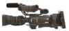
The illustration shows the GY-HD200U/
GY-HD200E/GY-HD201E HD CAMERA
RECORDER with the provided lens,
viewfinder and microphone
attached.
LST0512-001A
E
LST0512-001A
© 2006 Victor Company of Japan, Limited
LST0512-001A