JVC GY-HM700U 132 page operation manual for the GY-HM700 solid state camcorder
JVC GY-HM700U - Prohd Compact Shoulder Solid State Camcorder Manual
 |
View all JVC GY-HM700U manuals
Add to My Manuals
Save this manual to your list of manuals |
JVC GY-HM700U manual content summary:
- JVC GY-HM700U | 132 page operation manual for the GY-HM700 solid state camcorder - Page 1
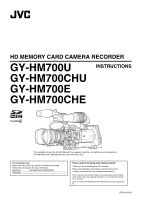
HD MEMORY CARD CAMERA RECORDER GY-HM700U INSTRUCTIONS GY-HM700CHU GY-HM700E GY-HM700CHE * The illustration shows the GY-HM700E with the supplied viewfinder, microphone and lens attached. * GY-HM700CHU/GY-HM700CHE does not come with a lens. For Customer Use: Enter below the Serial No. which - JVC GY-HM700U | 132 page operation manual for the GY-HM700 solid state camcorder - Page 2
on the marking label. If you are not sure of the type of power supplied to your home, consult your dealer or local power company. For appliance designed to operate from battery power, refer to the operating instructions. 10. For added protection for this product during a lightning storm, or when it - JVC GY-HM700U | 132 page operation manual for the GY-HM700 solid state camcorder - Page 3
, do NOT use any other power source. NOTE: The rating plate (serial number plate) is on the unit. REMARQUE: La plaque signalétique (plaque du numéro desérie) est située sur le cadre inférieur de l'unité. CAUTION: To prevent electric shock, do not open the cabinet. No user serviceable parts inside - JVC GY-HM700U | 132 page operation manual for the GY-HM700 solid state camcorder - Page 4
use cables not exceeding the following lengths: Port [DC INPUT] [Y/VIDEO], [PB], [PR] [AUDIO INPUT 1/2] [AUDIO OUTPUT] [PHONES] [IEEE1394] (HD/DV) [HD disturbed. In such case, please keep the JVC Technical Services users) If you wish to dispose of this product, please visit our web page http://www.jvc - JVC GY-HM700U | 132 page operation manual for the GY-HM700 solid state camcorder - Page 5
V - JVC GY-HM700U | 132 page operation manual for the GY-HM700 solid state camcorder - Page 6
(Supplied 20 Power Supply 20 Using AC Power (DC IN Power 21 Using a Battery Pack 21 Turning On/Off the Power 24 Setting the Clock (Initial Setting 25 Adjusting the Monitor Speaker 26 Adjusting Back Focus 27 Adjusting the LCD Monitor and Viewfinder 28 Tally Lamps 30 SDHC Cards 31 - JVC GY-HM700U | 132 page operation manual for the GY-HM700 solid state camcorder - Page 7
91 Status Screen Status Screen in Camera Mode 94 Status Screen in SD Card Mode 100 Status Screen in IEEE1394 Input Mode 102 Enlarged Status Display on Error Displays and Actions 122 Tally Lamps 123 Alarm Tone 123 Troubleshooting 124 Specifications 126 How to use this manual Ⅵ Symbols used - JVC GY-HM700U | 132 page operation manual for the GY-HM700 solid state camcorder - Page 8
mode bit rate (19/ 25 Mbps). Dual Media Slots Continuous recording is possible by loading two SDHC cards into the dual media slots, thereby allowing a long recording time. Wide Variety of Recording Formats This camera recorder supports various HD formats (1080i, 1080p, 720p) and can be used under - JVC GY-HM700U | 132 page operation manual for the GY-HM700 solid state camcorder - Page 9
Saving Ⅵ When this device is not in use, be sure to set the [POWER] switch to AOFFB in order to reduce power consumption. Batteries Ⅵ The following batteries can be used on this device. GY-HM700CHU/GY-HM700U : Dionic90 (Anton Bauer) GY-HM700CHE/GY-HM700E : Endura-7 (IDX) * Models with an E suffix - JVC GY-HM700U | 132 page operation manual for the GY-HM700 solid state camcorder - Page 10
Precautions for Proper Use (continued) Handling of SDHC Cards Ⅵ The access lamp lights up in red when data on the SDHC card is being accessed. Do not remove the SDHC card during data access (such as recording, playback, or formatting). Do not turn off the power or remove the battery and AC adapter - JVC GY-HM700U | 132 page operation manual for the GY-HM700 solid state camcorder - Page 11
starts up in Camera mode when the power is turned on. Memo: ● Images recorded on the SDHC card cannot be played back in this mode. However, you can check (play back) the most recently recorded image using the Clip Review function. (A Page 52) Media SD Card Mode Mode IEEE1394 Mode Purple Green - JVC GY-HM700U | 132 page operation manual for the GY-HM700 solid state camcorder - Page 12
14) LCD Monitor (A Page 11) C D E Side Control Panel (A Page 10) A Front Tally Lamp (A Page 30, 87) B Viewfinder Cable Clamp (A Page 20) C [ZEBRA ON/OFF] (Cheek Pad) (A Page 26) K Shoe For mounting separately sold lights and accessories. L Microphone Holder Lock Knob (A Page 19) M Microphone Holder - JVC GY-HM700U | 132 page operation manual for the GY-HM700 solid state camcorder - Page 13
a ZY X W W O V P Battery Mount (A Page 21) SDHC Slot (A Page 13) QR S Side Terminal (A Page 12) TU O Back Tally Lamp (A Page 30, 87) P [PHONES] Viewfinder Connector (20-pin) (A Page 20) W Accessory Mounting Screw Hole (x2) X [FOCUS ASSIST] Focus Assist Button (A Page 35) Y Record Button Lock - JVC GY-HM700U | 132 page operation manual for the GY-HM700 solid state camcorder - Page 14
focused area in either blue, red, or green. This enables easy and accurate focusing. (A Page 35) D [USER1], [USER2], [USER3] User Buttons (A Page 74) Use (A Page 66) F [ND FILTER] ND Filter Switch (A Page 43) G [ types. J [POWER] Power ON/OFF Switch Turns ON/OFF the power. When the power is OFF, - JVC GY-HM700U | 132 page operation manual for the GY-HM700 solid state camcorder - Page 15
used to set the number of frames during Variable Frame REC. (A Page 56 [Variable Frame REC]) (A Page 75 [AE LEVEL]) Ⅵ During Media mode (SD Card Card Mode) Media Mode (IEEE1394 Mode) USB Mode Color Blue/Purple Green Orange Orange Memo: ● You can select whether to light up the indicator using Focus - JVC GY-HM700U | 132 page operation manual for the GY-HM700 solid state camcorder - Page 16
Signal Output Terminal (BNC) (A Page 114) D [PR] PR Video Signal Output Terminal (BNC) (A Page 114) E [REMOTE] Remote Terminal (A Page 119) F [DC INPUT] DC Input Terminal (A Page 21) Input terminal for DC 12 V power supply. Connects with an AC adapter. G [AUDIO OUTPUT] Audio Output Terminal (RCA - JVC GY-HM700U | 132 page operation manual for the GY-HM700 solid state camcorder - Page 17
and cause injuries. ● Check the instruction manual provided with the shoulder belt before using. B Accessory Connector (Connects to an optional accessory) C Battery Mounting Folder (A Page 21) The shape is different for GY-HM700CHU/GY-HM700U and GY-HM700CHE/GY-HM700E. * The above is the illustration - JVC GY-HM700U | 132 page operation manual for the GY-HM700 solid state camcorder - Page 18
Introduction Names of Parts (continued) Zoom Lens (Supplied with GY-HM700U/GY-HM700E only) CANON KT14 x 4.4KRSJ C B A IRIS A M T W RET REC DE F G HI J M K L MANU. SERVO ZOOM M NO A Focus Ring B Zoom Lever/Ring To operate zoom with this lever, turn the [ZOOM] switch M and set it to AMANU - JVC GY-HM700U | 132 page operation manual for the GY-HM700 solid state camcorder - Page 19
Recording Device For GY-HM700CHU/GY-HM700U VTR PL Mount Film Lens 16 mm PL Mount Film Lens adapter HZ-CA13U Zoom Servo Control HZ-ZS13B 1/3 Zoom Lens KT14x4.4KRSJ (CANON) (GY-HM700U/GY-HM700E only) Battery Mount GY-HM700CHU/GY-HM700U : Gold Mount GY-HM700CHE/GY-HM700E : V Mount Standard - JVC GY-HM700U | 132 page operation manual for the GY-HM700 solid state camcorder - Page 20
status screen and menu screen are also displayed in the video image of the video signal output terminal. (A Page 86) Viewfinder [DISPLAY] Button M / H ] 0dB / 9dB / 12dB USER 1 BARS USER 2 B.STRETCH3 USER 3 LOAD FILE RET CLIP REVIEW SKIN/SPOT SPOT METER AELEVEL AE LEVEL/VFR STBY - JVC GY-HM700U | 132 page operation manual for the GY-HM700 solid state camcorder - Page 21
Ⅵ Status Screen (VF/LCD) During Clip Playback in Media Mode (SD Card Mode) (A Page 100) The display switches between the 3 screen types with every press During enlarged display of the status on the LCD monitor screen, the video image remains displayed on the viewfinder. 282min STATUS 1 Screen 17 - JVC GY-HM700U | 132 page operation manual for the GY-HM700 solid state camcorder - Page 22
0 Screen and alarm will be displayed. (A Page 122 [Error Displays and Actions]) 30/24 fps A 1min B 1min STBY that indicate the luminance level of the video image can be displayed on this camera Pattern]) Zebra Pattern [Main Menu] Screen Memo: ● Use the [ZEBRA ON/OFF] switch in front to turn - JVC GY-HM700U | 132 page operation manual for the GY-HM700 solid state camcorder - Page 23
Preparations Attaching Accessories Attaching the Zoom Lens (Supplied with GY-HM700U/GY-HM700E only) Hole 13 Pin REC 2 Clamp 4 1 Loosen the mount ring. 2 Attach the zoom lens such that the pin matches the hole of the mounting area. 3 - JVC GY-HM700U | 132 page operation manual for the GY-HM700 solid state camcorder - Page 24
Attaching Accessories (continued) Attaching the Viewfinder (Supplied) 1 Slide the viewfinder in the direction of the arrow to attach it. 2 Turn the slide lock ring to secure the position of the viewfinder. Slide Lock Ring 2 Power Supply To use this camera recorder, you can attach a battery pack - JVC GY-HM700U | 132 page operation manual for the GY-HM700 solid state camcorder - Page 25
recommended batteries. Heavy batteries may fall off if not used correctly. ● See the battery instruction manual on how to charge the battery. [DC INPUT] DC Cable DC OUTPUT AC Adapter 2 Set the [POWER] switch of the camera recorder to AONB after turning on the AC adapter. Power will be supplied to - JVC GY-HM700U | 132 page operation manual for the GY-HM700 solid state camcorder - Page 26
continued) Attaching the Battery (GY-HM700CHU/GYHM700U) Use the Dionic90 (Anton Bauer) battery. 1 Align the battery guide pins (x3) with the battery, adapter, and guide hole and insert straight. Guide Hole (x3) Release Lever Guide Pins Attaching the Battery (GY-HM700CHE/GYHM700E) Use the Endura - JVC GY-HM700U | 132 page operation manual for the GY-HM700 solid state camcorder - Page 27
Monitor Screens The power status is displayed on the status and menu screens. If the battery or supplied voltage from the AC adapter is low, a warning will be displayed in red. Note: ● If the battery in use is not a recommended one, the battery mark which indicates the battery level may not appear - JVC GY-HM700U | 132 page operation manual for the GY-HM700 solid state camcorder - Page 28
Button [POWER] Switch Ⅵ Camera mode Camera images are output on the viewfinder and LCD monitor. When a recordable SDHC card is SDHC card is not possible in Camera mode. However, you can use the Clip Review function to check the most recently recorded video clip. (A Page 52) Ⅵ Media mode (SD Card - JVC GY-HM700U | 132 page operation manual for the GY-HM700 solid state camcorder - Page 29
displayed on the LCD monitor and viewfinder and be recorded to the SDHC card. ● The value of the year can be set in the setting screen appears. [POWER] Switch 1 Set the [POWER] switch to AONB. The [Initial Setting] screen appears. Ⅵ For GY-HM700CHU/GY-HM700U 2 Set the date GY-HM700CHE/GY-HM700E 25 - JVC GY-HM700U | 132 page operation manual for the GY-HM700 solid state camcorder - Page 30
: ● To perform the settings while looking at the monitor screen connected to the video signal output terminal, set [Analog Out Char.] or [SDI Out Char.] in Display in Different Operation Modes During Camera Mode During Media Mode (SD Card Mode) During Media Mode (IEEE1394 Mode) Date/time of the - JVC GY-HM700U | 132 page operation manual for the GY-HM700 solid state camcorder - Page 31
). 2 Set the zoom mode switch to AMANU.B (manual). 3 Turn to open the iris ring. Adjust the lighting such that the optimum image level can be obtained. 4 Turn the zoom lever to set the lens to the maximum telephoto position. 5 Turn the focus ring to adjust the focus of the object. 6 Set the lens to - JVC GY-HM700U | 132 page operation manual for the GY-HM700 solid state camcorder - Page 32
LCD monitor screen. ● During Camera mode, SD Card mode (playback), or IEEE1394 mode ● Use the [LCD PEAKING +/-] button to adjust the Focus Ring Eyepiece Slide Lock Ring Eyepiece Lock Ring Note: ● A high-definition viewfinder is used on this camera recorder in order to provide an accurate focusing - JVC GY-HM700U | 132 page operation manual for the GY-HM700 solid state camcorder - Page 33
Adjust the position and angle of the viewfinder. Ⅵ Adjusting the Visibility Turn the eyepiece focus ring to sharpen the image on the viewfinder screen. Ⅵ Adjusting the Viewfinder Screen Adjusting contour and brightness ● Use the [VF BRIGHT] knob to adjust the brightness of the viewfinder screen - JVC GY-HM700U | 132 page operation manual for the GY-HM700 solid state camcorder - Page 34
or remaining space on the SDHC card is low, the lamps blink. (Camera mode only) * Set using [Tally System]/[Front Tally]/[Back Tally] in the [Main Menu]B[Others] menu. (A Page 87) Front Tally Lamp Back Tally Lamp [Tally System] ^ Menu Setting [Front Tally]/[Back Tally] *1 Off Camera Recorder - JVC GY-HM700U | 132 page operation manual for the GY-HM700 solid state camcorder - Page 35
and B. Lamp Lights up in red Lights up in green Light goes out Slot Status Inserted SDHC card is being accessed. (writing/reading data) Do not turn off the power of the camera recorder or remove the SDHC card. On standby. Inserted SDHC card can be used for recording or playback. ● SDHC card is not - JVC GY-HM700U | 132 page operation manual for the GY-HM700 solid state camcorder - Page 36
button. 5 Formatting starts. Formatting (Initializing) SDHC Cards When the following cards are inserted, AFormatting RequiredB appears. Format the card using the camera recorder menu. ● Unformatted SDHC cards ● SDHC cards formatted under different specifications * For details of the menu operation - JVC GY-HM700U | 132 page operation manual for the GY-HM700 solid state camcorder - Page 37
time is only a guide. Differences may occur depending on the SDHC card in use and the battery condition. (A Page 71 [Camera Resolution]) (A Page 71 [Frame & Bit Rate]) QuickTime/MP4 Camera Resolution Bit Rate 1280x720 HQ 1440x1080 1920x1080 1440x1080 SP 1280x720 SP SDHC Card Size 4 GB 8 GB 16 - JVC GY-HM700U | 132 page operation manual for the GY-HM700 solid state camcorder - Page 38
Shooting Basic Shooting Procedures 1 Front Tally Lamp [REC] Button Back Tally Lamp 3 2 5 4 [POWER] Switch [REC] Button Preparations 1 Attach the accessories. (A Page 19) 2 Supply battery or AC adapter power to the camera recorder. (A Page 21) 3 Insert an SDHC card. (A Page 31) 4 Turn on the - JVC GY-HM700U | 132 page operation manual for the GY-HM700 solid state camcorder - Page 39
be played back continuously on the camera recorder. Clips may be recorded across both SDHC cards in card slot A and B depending on the recording time of the clip. When copying clips to a HDD using a PC, it is recommended to use [JVC Clip Manager Software], which is found in the bundled CD-ROM, to - JVC GY-HM700U | 132 page operation manual for the GY-HM700 solid state camcorder - Page 40
. Selecting a Video Format Select a [Record Format] from the list of formats. The selectable [Frame & Bit Rate] changes according HD 30p(HQ) Full HD 50i(HQ) Full HD 25p(HQ) Full HD 24p(HQ) Full HD File Format MP4 Record Format Camera Resolution Horizontal×Line 1280x720 Frame & Bit Rate - JVC GY-HM700U | 132 page operation manual for the GY-HM700 solid state camcorder - Page 41
light sensitivity when there is insufficient illumination on the object. You can set the gain of the video Gain Mode (Manual Gain Switching) You can select the gain of the video amplifier using the [GAIN] video amplifier is automatically set according to the brightness of the object. In this case - JVC GY-HM700U | 132 page operation manual for the GY-HM700 solid state camcorder - Page 42
Shutter Speed When shutter is ON, use the cross-shaped button (JK) to set the shutter speed. Shutter speed differs according to the video format and variable frame rate settings. Ⅵ During modes other than Variable Frame REC Shutter Camera Resolution/ Frame & Bit Rate 720/60p 720/30p 1080/60i - JVC GY-HM700U | 132 page operation manual for the GY-HM700 solid state camcorder - Page 43
Camera Resolution/ Shutter Frame & Bit Rate 720/25p Frame Rate 50, 25, 12.5 40, 20, 10 J Button 1/10000 1/10000 1/40.00 Memo: ● Shutter speed is usually displayed in seconds (SEC). However, only when [Frame & Bit Rate] is set to A24p(SP)B, A24p(HQ)B, A25p(SP)B, or A25p(HQ)B, the speed can be - JVC GY-HM700U | 132 page operation manual for the GY-HM700 solid state camcorder - Page 44
white balance when the main light source illuminating the object changes. [WHT.BAL] Selection Switch [FULL AUTO] Switch [POWER] Switch [AWB] Button Manual White Balance Mode (Manual Switching) You can select the white balance with the [WHT.BAL] selection switch. Use the [WHT.BAL] selection switch - JVC GY-HM700U | 132 page operation manual for the GY-HM700 solid state camcorder - Page 45
Use another white object and adjust the white balance again. ERROR : LOW LIGHT Insufficient illumination. Displayed when the lighting is dark. Increase the lighting and adjust the white balance again. ERROR : OVER LIGHT White Balance. ● When the power of the camera recorder is turned on with - JVC GY-HM700U | 132 page operation manual for the GY-HM700 solid state camcorder - Page 46
the screen may not be adjusted. In this case, green and yellow colors may appear on the set to the optimum brightness by increasing the lighting. B When using zoom lens, set to the center of the value that compares the average values of the R, G, B channels in the evaluated value detection frames at - JVC GY-HM700U | 132 page operation manual for the GY-HM700 solid state camcorder - Page 47
of the ND filter [1/16] [1/4] [OFF] Reduces the amount of incident light to 1/16. Select this filter position is set to AOffB by default. To display the position of the ND filter, set [Filter] in the [LCD/VF]B[Status Display] menu to AOnB. (A Page 84) ● It is recommended to use the ND filter - JVC GY-HM700U | 132 page operation manual for the GY-HM700 solid state camcorder - Page 48
setting when connecting to a dynamic microphone. [MIC+48V] Use this setting when connecting to a microphone (phantom microphone) that requires a +48 V power supply. Note: ● When connecting a device that does not require a +48 V power supply, make sure that it is not set to the AMIC+48VB position - JVC GY-HM700U | 132 page operation manual for the GY-HM700 solid state camcorder - Page 49
if the [FULL AUTO] switch is set to AONB. (A Page 75) Ⅵ Using Stereo Type Earphone Jack When a stereo type earphone jack is connected, perform the in the camera recorder. Alarm tone is also output when the SDHC card is full or when the battery is low. (A Page 123) ● Alarm tone is not output during - JVC GY-HM700U | 132 page operation manual for the GY-HM700 solid state camcorder - Page 50
display for [IEEE1394] input is not supported. ● Values recorded on the SDHC card is displayed in Media mode. Setting Display LCD/VF Display VIDEO Output Display TC Time When [Main Menu]B[LCD/ When [Analog Code VF]B[Status Display]B[TC/ Out Char.] or [SDI UB User's Bit UB] is set to AOnB - JVC GY-HM700U | 132 page operation manual for the GY-HM700 solid state camcorder - Page 51
. Sets the run mode of the time code generator to nondrop frame mode. Use this setting when placing emphasis on the number of frames. Memo: Drop frame/non-drop frame mode ● When the frame rate setting in [Main Menu]B[Record Set] B[Record Format]B[Frame & Bit Rate] is 60 (30), the actual number of - JVC GY-HM700U | 132 page operation manual for the GY-HM700 solid state camcorder - Page 52
displayed as ARegenerationB and cannot be selected. 2 Use the cross-shaped button (H I) to place A and F can be specified for the user's bit. 3 Check the values and press cannot be made in the following cases. ● [TC GENE.] switch is ] Screen (During drop frame) [UB Preset] Screen Memo: ● Press - JVC GY-HM700U | 132 page operation manual for the GY-HM700 solid state camcorder - Page 53
User's Bit Without Opening the Menu Memo: ● Settings cannot be made in the following cases screen appears. Cursor 2 Set the user's bit. Use the cross-shaped button (H I) to user's bit already recorded on the SDHC card is recorded. Memo: ● When the [TC GENE.] switch is set to AREGENB, the framing - JVC GY-HM700U | 132 page operation manual for the GY-HM700 solid state camcorder - Page 54
Shooting Setting Zebra Pattern When the luminance level range for displaying zebra patterns is specified, diagonal lines (zebra pattern) are displayed at areas with the specified luminance levels during shooting. Specifying the Brightness (Luminance) Level Range for Displaying Zebra Pattern Memo: ● - JVC GY-HM700U | 132 page operation manual for the GY-HM700 solid state camcorder - Page 55
during shooting is displayed. This function is useful when setting video or stage lighting or when specifying camera exposure. A cursor the screen. Frame may also be stopped at the current positions. [Manual] Displays the brightness (%) of the specified position. Color of frame indicating the - JVC GY-HM700U | 132 page operation manual for the GY-HM700 solid state camcorder - Page 56
Spot Meter (continued) Viewing Recorded Videos Immediately (Clip Review) Ⅵ When [Manual] is selected A [SPOT METER of the camera recorder are different from the video format (Camera Resolution/Frame & Bit Rate) of the clip. (A Page 71) Memo: ● To use this function, assign AClip ReviewB to any of - JVC GY-HM700U | 132 page operation manual for the GY-HM700 solid state camcorder - Page 57
last clip is less than 5 seconds, the whole clip is played back. ● Only video clips in the currently selected slot can be reviewed. ● When there are no clips in the selected slot, Clip Review function is disabled. ● Clip Review is unavailable when Clip Continuous REC is paused (STBYC, red text). To - JVC GY-HM700U | 132 page operation manual for the GY-HM700 solid state camcorder - Page 58
)BASTBYPB is displayed. ● When the SDHC card becomes full during recording, recording stops and ASTOPPB is displayed. ● Video and audio before the above mentioned time may not be recorded after recording starts in the following cases. ● Immediately after power on ● Immediately after switching from - JVC GY-HM700U | 132 page operation manual for the GY-HM700 solid state camcorder - Page 59
card slot status indicator lights up in red. ● A new AclipB is generated from here. Memo: ● The following operations are unavailable while recording is paused (STBYC, red text). ● Clip Review (A Page 52) ● Switching SDHC card slots ● Switching operation mode (A Page 7) ● Files are split into sizes - JVC GY-HM700U | 132 page operation manual for the GY-HM700 solid state camcorder - Page 60
you to obtain smooth slow motion or quick motion videos. Using different frame rate settings for recording and playback, videos captured at normal speed can be played back more smoothly than those in low or high speed playback. To enable Variable Frame REC, the following two settings are required at - JVC GY-HM700U | 132 page operation manual for the GY-HM700 solid state camcorder - Page 61
. Use the thumbnail menu [Detailed Properties] to switch display. (A Page 61) The first frame of the recorded clip on the SDHC card is video playback. Name A Cursor Description Indicates the selected clip. Use the crossshaped button (JKH I) to move the cursor. After power is turned on and SDHC card - JVC GY-HM700U | 132 page operation manual for the GY-HM700 solid state camcorder - Page 62
Record Format]B[Frame & Bit Rate] of the [Main Menu] screen. (A Page 71) Displays the [running number/total number of clips] of the displayed clips. : Ample battery power. : Slightly reduced battery power. : Low battery power. : Empty battery power. (Blinks in red) : External power supply connected - JVC GY-HM700U | 132 page operation manual for the GY-HM700 solid state camcorder - Page 63
current clip is continued from another SDHC card when recording is divided and made on several SDHC cards. C Continue Mark This mark indicates that the current clip will continue to another SDHC card when recording is divided and made on several SDHC cards. Guide for the current operation buttons - JVC GY-HM700U | 132 page operation manual for the GY-HM700 solid state camcorder - Page 64
Use the crossshaped button (H I) to move the cursor. After power is turned on and SDHC card size Frame Rate : Frame rate Bit Rate : Bit rate Audio : Audio format Start TC : Time code at the start of recording End TC : Time code at the end of recording Duration : Clip length USB : User - JVC GY-HM700U | 132 page operation manual for the GY-HM700 solid state camcorder - Page 65
an SDHC card can be displayed on the LCD monitor and viewfinder. Memo: ● When [HD/SD-SDI Out] in the [A/V Out] menu is set to AHD-SDIB or ASD-SDIB, time code is also output from the [HD/SD-SDI] output terminal. (A Page 86) ● User's bit output from the [HD/SD-SDI] output terminal is used as - JVC GY-HM700U | 132 page operation manual for the GY-HM700 solid state camcorder - Page 66
PC. 2 Press the [USER2] button. A screen to confirm deletion appears. 3 Use the cross-shaped button (JK) to select [Delete] and press the Set button (R). A clip with OK mark is selected. ● Write-protect switch of the SDHC card is set ( is displayed). Ⅵ During Thumbnail Screen Ⅵ Deleting with [USER2 - JVC GY-HM700U | 132 page operation manual for the GY-HM700 solid state camcorder - Page 67
4 Use the cross-shaped button (JK) to select [Delete] and press the Set button (R). Deleting starts. 3 Memo: ● Button operations are unavailable during deletion. The deleting operation - JVC GY-HM700U | 132 page operation manual for the GY-HM700 solid state camcorder - Page 68
Mark Memo: ● The [USER1] button is disabled (displayed in gray) and OK marks cannot be appended when the write-protect switch of the SDHC card is set ( is displayed). ● AOK Mark Added...B is displayed when changing marks and other operations are unavailable. Ⅵ During Playback or Pause Screen 1 Press - JVC GY-HM700U | 132 page operation manual for the GY-HM700 solid state camcorder - Page 69
mark is deleted. 1 Memo: ● The [USER1] button is disabled (displayed in gray) and OK marks cannot be deleted when the write-protect switch of the SDHC card is set ( is displayed). ● AOK Mark Added...B/AOK Mark Deleted...B is displayed when changing marks and other operations are unavailable. 65 - JVC GY-HM700U | 132 page operation manual for the GY-HM700 solid state camcorder - Page 70
reduced battery power. : Low battery power. : Empty battery power. (Blinks in red) : External power supply connected. Memo: ● If the battery in use is not a recommended one, the battery mark which indicates the battery level may not appear. H Header I Scroll Bar J Setting Values K Operation Guide - JVC GY-HM700U | 132 page operation manual for the GY-HM700 solid state camcorder - Page 71
to be changed. A list of setting values C appears in a popup. Guide for the current operation buttons. A pop-up displaying a list of setting values subname or up to 4 characters for the [Clip Name Prefix]. Select a character using the key cursor D, and press the Set button (R) to input the selected - JVC GY-HM700U | 132 page operation manual for the GY-HM700 solid state camcorder - Page 72
Mode (A Page 71) Clip Set (A Page 72) File Format Camera Resolution Frame & Bit Rate Clip Name Prefix Reset Clip Number Audio Set (A Page 72) Input1 Mic Ref. Input2 Mic Ref. Mic Wind Cut Audio Ref. Level Audio Limiter Test - JVC GY-HM700U | 132 page operation manual for the GY-HM700 solid state camcorder - Page 73
Output Terminal Down Convert Set Up HD/SD-SDI Out Analog Out Char. SDI Out Char. Audio Monitor Alarm Level Mode LED Tally System Front Tally Back Tally 1394 Rec Trigger 1394 Auto Power Off Reset All Date/Time Time Zone System Information Format Media Restore Media Load File... Store File... Reset - JVC GY-HM700U | 132 page operation manual for the GY-HM700 solid state camcorder - Page 74
the alarm volume, front/back tally lamp settings, status indicator, 1394 input settings, date/ time, time zone, and other settings. It can also be used to reset the menu settings to their default values. (A Page 87) Item for formatting or restoring the SDHC card. (A Page 89) Displays the [Setup - JVC GY-HM700U | 132 page operation manual for the GY-HM700 solid state camcorder - Page 75
the format of the file to be recorded to the SDHC card. Note: ● AMP4B can only be selected when KA-MR100G (Memory Recorder) is connected. For selecting the size of the recorded images. (Horizontal x vertical) The selectable values of [Frame & Bit Rate] vary according to the setting of this item. For - JVC GY-HM700U | 132 page operation manual for the GY-HM700 solid state camcorder - Page 76
the SDHC card. Enter any of the 38 characters including alphabets (upper case), numbers (0 to 9), "_" (underscore), and "-" (hyphen) using the dB as the reference value. For selecting whether to cut the low frequencies of the audio input signals (low-cut) when the [AUDIO INPUT 1/2] button is set to - JVC GY-HM700U | 132 page operation manual for the GY-HM700 solid state camcorder - Page 77
Set... FULL AUTO... EEI Variable Step For specifying shutter-related settings. Use this item to set to AStepB (fixed value) or AVariableB when operating function at medium speed. Slow : Runs the Smooth Trans function at low speed. Off : Deactivates the Smooth Trans function. For specifying the - JVC GY-HM700U | 132 page operation manual for the GY-HM700 solid state camcorder - Page 78
Assigns the functions of [Stretch Level] and [Compress Level] under [Black Toe] in the [Camera Process] menu. (A Page 76) LENS RET Clip Review OK Mark Focus Assist Clip Review Last 5 sec Top 5 sec CLIP For assigning a function to the [RET] button on the lens. This function does not work if the - JVC GY-HM700U | 132 page operation manual for the GY-HM700 solid state camcorder - Page 79
Max&Min Min Max Manual For specifying the frames during Variable Frame REC, and operates as the AE LEVEL setting button in other cases. (A Page 56) AE LEVEL : Operates as the AE LEVEL setting button at all times. Disable : Disables the button. FULL AUTO Item This is used to set specific - JVC GY-HM700U | 132 page operation manual for the GY-HM700 solid state camcorder - Page 80
, which compresses video signals beyond a certain level to show the gradation of the highlighted portion. To check the gradation of a bright area, set to AManualB and adjust the knee point manually. Manual : Enables manual adjustment of the knee point (starting point of knee operation) using ALevelB - JVC GY-HM700U | 132 page operation manual for the GY-HM700 solid state camcorder - Page 81
setting the point to apply white clip for input video signals with a high luminance level. 100% : Sets to a gamma curve that focuses on the gradation expression of This item is used to adjust [Color Matrix] to a color according to the user's preference. This Restores all items in the [Camera - JVC GY-HM700U | 132 page operation manual for the GY-HM700 solid state camcorder - Page 82
according to the object. High : Emphasizes the high frequency range. Use this when shooting objects with fine patterns. Middle : Emphasizes the intermediate frequency range. Low : Emphasizes the low frequency range. Use this when shooting objects with large patterns. For specifying the correction - JVC GY-HM700U | 132 page operation manual for the GY-HM700 solid state camcorder - Page 83
For specifying white shading adjustment settings. (A Page 42) Preset : Sets white shading adjustment to a fixed level. Manual adjustment is disabled. Manual : Enables manual white shading adjustment. For making white shading adjustments. Memo: ● This item cannot be selected when [Shading Mode - JVC GY-HM700U | 132 page operation manual for the GY-HM700 solid state camcorder - Page 84
Zebra, markers (Aspect Marker/Safety Zone/Center Mark), Focus Assist mode, and ABB mode in the [VF Display This item is used to adjust [Color Matrix] to a color according to the user's preference. (A Page For adjusting the red/yellow level of the video toward red. Increase the number : Enhances the - JVC GY-HM700U | 132 page operation manual for the GY-HM700 solid state camcorder - Page 85
the cyan component of green/cyan. Decrease the number : Reduces the cyan component of green/cyan. For adjusting the cyan/blue level of the video toward cyan. Increase the number : Enhances the cyan component of cyan/blue. Decrease the number : Reduces the cyan component of cyan/blue. For adjusting - JVC GY-HM700U | 132 page operation manual for the GY-HM700 solid state camcorder - Page 86
when placing emphasis on the number of frames. Drop : Internal time code generator works in the drop-frame mode. Use this setting when placing emphasis on the recording time. Memo: ● This item can be set only when the frame rate of [Frame & Bit Rate] in the [Record Set]B[Record Format] menu - JVC GY-HM700U | 132 page operation manual for the GY-HM700 solid state camcorder - Page 87
indicated in bold characters. Item Focus Assist Color Level Zebra Top1 Bottom1 Setting Values ACCU-Focus Normal Blue Green Red High Middle Low 2Patterns 1Pattern Over, 100% to Peaking Frequency High Middle Low For setting the frequency range for applying contour enhancement using the [VF PEAKING - JVC GY-HM700U | 132 page operation manual for the GY-HM700 solid state camcorder - Page 88
used to set the status displays on the LCD monitor and viewfinder screens. Item F.No/Iris Indicator Setting Values F.No+Iris Ind. F.No Off Filter On Off Video video format mode. Off : Hides the video format mode. For specifying whether to display the remaining space of the recording SDHC card - JVC GY-HM700U | 132 page operation manual for the GY-HM700 solid state camcorder - Page 89
time code or user's bit rate. For specifying power and time cannot be obtained otherwise. For more details, refer to the instruction manual of the Anton Bauer battery. ● The remaining battery power Frame & Bit Rate] is set to A24p(SP)B, A24p(HQ)B, A25p(SP)B, or A25p(HQ)B. When [Frame & Bit Rate - JVC GY-HM700U | 132 page operation manual for the GY-HM700 solid state camcorder - Page 90
Memo: ● When DV signals are input from the [IEEE1394] terminal, AHD-SDIB cannot be selected. ● User's bit output from the [HD/SD-SDI] output terminal is used as a flag to determine valid video signals. Therefore, accurate values will not be output. Analog Out Char. On Off For selecting whether to - JVC GY-HM700U | 132 page operation manual for the GY-HM700 solid state camcorder - Page 91
to R). When a monitor speaker is used, only the audio sound of CH-1 Tally System Front Tally Back Tally Setting Values High Middle Low Lights up as below according to the operation mode. (A Page 7) Off : Turns off the indicator. Operation Mode Color Camera Mode Blue/Purple Media Mode (SD Card - JVC GY-HM700U | 132 page operation manual for the GY-HM700 solid state camcorder - Page 92
] button and the Clip Review function will be disabled. ● When [1394 Rec Trigger] is set to ASplitB, the [REC] button on the side of the camera recorder becomes a REC Start/Stop button for the external device. (A Page 10) ● When the [REC] button is pushed immediately after the power is turned on or - JVC GY-HM700U | 132 page operation manual for the GY-HM700 solid state camcorder - Page 93
], and press the Set button (R) to restore the SDHC card. (A Page 33 [Restoring the SDHC Card]) Memo: ● This item appears only when the SDHC card needs to be restored. However, it is not selectable when recording in Camera mode and during Clip Review. Setup File Manage Menu Menu settings and - JVC GY-HM700U | 132 page operation manual for the GY-HM700 solid state camcorder - Page 94
Favorites Menu) You can select and add/edit frequently used menu items freely to create a personal menu screen Adding items to [Favorites Menu] cannot be performed in the following cases. [USER1 Add] is displayed in gray in the operation guide. ● Selected item is already added to [Favorites Menu]. ● - JVC GY-HM700U | 132 page operation manual for the GY-HM700 solid state camcorder - Page 95
Editing [Favorites Menu] You can delete or change the order of the items added to [Favorites Menu]. Ⅵ Deleting Items from [Favorites Menu] 1 Open the [Favorites Menu] screen. A Press the [MENU] button to open the [Main Menu] screen. B Press the [STATUS] button to open the [Favorites Menu] screen. 2 - JVC GY-HM700U | 132 page operation manual for the GY-HM700 solid state camcorder - Page 96
Menu Display and Detailed Settings Adding/Editing Frequently Used Menu Items (Favorites Menu) (continued) Editing [Favorites Menu] (continued) Ⅵ Changing the Order of Items in [Favorites Menu] [USER1] Button [USER2] Button [MENU] Button Set Button (R) - JVC GY-HM700U | 132 page operation manual for the GY-HM700 solid state camcorder - Page 97
4 Select the position to move to with the cross-shaped button (JK). Move the position selection bar with the cross-shaped button (JK) and select a position to move to. 5 Press the Set button (R). The selected item moves to the new position. 4 5 6 Press the [USER1] button. The option menu to exit the - JVC GY-HM700U | 132 page operation manual for the GY-HM700 solid state camcorder - Page 98
to record to the card in the slot POFF : Power OFF Indicates whether the the shutter speed varies according to the video format settings. (A Page 38) Displays Auto White balance mode is ON MANU : Manual White Balance mode (only during control using the remote control) Appears when [Black Toe] - JVC GY-HM700U | 132 page operation manual for the GY-HM700 solid state camcorder - Page 99
Active SDHC slot is switched automatically or using the [SLOT SELECT] button in Camera mode. TRIGGER TO HD, TRIGGER TO DV Recording command is sent out from the [IEEE1394] terminal FRAME RATE rrrr/pp fps (rrrr: recording frame rate, pp: playback frame rate) Variable frame rate is adjusted using - JVC GY-HM700U | 132 page operation manual for the GY-HM700 solid state camcorder - Page 100
selected slot. (White card) A! : SDHC card requires restoring or formatting, or SDHC card is not supported (not of class 6 type). A : Write-protect switch of SDHC card is set. Displays the current status of the power supply in use. Display Description 12.3V Currently powered by an AC adapter - JVC GY-HM700U | 132 page operation manual for the GY-HM700 solid state camcorder - Page 101
external device. For details, refer to the instruction manual of the corresponding external device. Memo: ● Only warnings are displayed in the STATUS 0 and STATUS 4 Screens. J Time Code (TC)/ User's Bit (UB) Displays the time code (hour:minute:second:frame) or user's bit data. Example: Time code - JVC GY-HM700U | 132 page operation manual for the GY-HM700 solid state camcorder - Page 102
separately. A : Currently selected slot. (White card) A! : SDHC card requires restoring or formatting, or SDHC card is not supported (not of class 6 type). A : Write-protect switch of SDHC card is set. Displays the file format for recording to the SDHC card (File Format) that is specified at - JVC GY-HM700U | 132 page operation manual for the GY-HM700 solid state camcorder - Page 103
/ M / H ] 0dB / 9dB / 12dB B USER 1 BARS USER 2 B.STRETCH3 C USER 3 LOAD FILE RET CLIP REVIEW D A B 1min 1min SKIN/SPOT AE LEVEL SPOT METER the setting status of the [RET] button on the lens. (CLIP REVIEW, FOCUS ASSIST, OK MARK) Displays the setting status of the [SKIN AREA/SPOT - JVC GY-HM700U | 132 page operation manual for the GY-HM700 solid state camcorder - Page 104
Item A OK Mark B Resolution C Frame Rate/Bit Rate D Media E Clip Information F Time Code (TC)/ User's Bit (UB) Description Appears when an OK mark is added. (A Page 64) Displays the video image resolution. (1920ן1080, 1440ן1080, 1280ן720) Displays the frame rate and bit rate in pairs. (60p HQ - JVC GY-HM700U | 132 page operation manual for the GY-HM700 solid state camcorder - Page 105
power supply in use. Display Description 12.3V Currently powered by an AC adapter. The current voltage is shown on the right. If the supplied voltage from the AC adapter is low, the voltage value will be displayed in red as a warning. 12.3V 200min 30% RES Currently powered by a battery. When - JVC GY-HM700U | 132 page operation manual for the GY-HM700 solid state camcorder - Page 106
B Resolution C Audio Level Meter D Voltage/Battery Power Description Displays the frame rate and bit rate in pairs. (60p HQ, 30p HQ, 60i HQ, 60p SP, 30p SP, 60i SP, 50p HQ, 25p HQ, 50i HQ, 50p SP, 25p SP, 50i SP, 24p HQ, 24p SP) Displays the video image resolution. (1920ן1080, 1440ן1080, 1280 - JVC GY-HM700U | 132 page operation manual for the GY-HM700 solid state camcorder - Page 107
the write-protect switch of the SDHC card is set. Appears as [OK] when the currently played clip is appended with an OK mark. Displays the video format that is set. (A Page 36) Displays the current status of the power supply in use. Display Description 12.3V Currently powered by an AC adapter - JVC GY-HM700U | 132 page operation manual for the GY-HM700 solid state camcorder - Page 108
[Center Mark] = AOnB Safety Zone Center Mark Aspect Marker You can turn ON/OFF the safety zone and center mark displays as shown below using the [Aspect Ratio], [Safety Zone] and [Center Mark] settings of [Marker Setting] in the [LCD/VF] menu. (A Page 84) [Aspect Marker] Display Ⅵ When [Aspect - JVC GY-HM700U | 132 page operation manual for the GY-HM700 solid state camcorder - Page 109
[Safety Zone] Display Ⅵ When [Aspect Ratio] = A4:3B, [Aspect Marker] = AHalftoneB, and [Center Mark] = AOnB [Off] [95%] [93%] [90%] [80%] [88%] [Center Mark] Display Ⅵ When [Aspect Ratio] = A4:3B, [Aspect Marker] = AHalftoneB, and [Safety Zone] = A80%B [Off] [On] Ⅵ When [Aspect Ratio] = - JVC GY-HM700U | 132 page operation manual for the GY-HM700 solid state camcorder - Page 110
used to reduce the contour enhancement of video signals for only the skin areas so as to produce a smoother skin tone. Preparations Before Using areas in color. Skin Color Detection Frame Ⅵ Color Range Setting 1 Place the Marker]/ [Safety Zone]/[Center Mark]), [Focus Assist] mode, and [B] mode in - JVC GY-HM700U | 132 page operation manual for the GY-HM700 solid state camcorder - Page 111
] button that is assigned with ABarsB. Color bars are output. Memo: ● During color bar output, you can select whether to output the reference audio signals using [Test Tone] in the [Audio Set] menu. (A Page 72) ● Color bars are not output when the [FULL AUTO] switch is set to AONB but [Bars] in - JVC GY-HM700U | 132 page operation manual for the GY-HM700 solid state camcorder - Page 112
color matrix of the camera recorder can be adjusted to a color of the user's preference. When shooting is performed using multiple cameras, the colors of the different cameras can be adjusted, and a color of the user's preference can be set on this camera recorder. 13 saturation parameters and 3 hue - JVC GY-HM700U | 132 page operation manual for the GY-HM700 solid state camcorder - Page 113
B&Mg B Level B&Mg Mg Level R I YI Mg B Increase the value: Corrected Y increases Decrease the value: Corrected Y decreases G Cy R I Increase the value: Mg Corrected Y decreases YI Decrease the value: B Corrected Y increases G Cy 3 Adjust Yl&G Mask Range. Adjusting [Yl&G Yl Level] and [Yl - JVC GY-HM700U | 132 page operation manual for the GY-HM700 solid state camcorder - Page 114
[Black Toe] in the [Camera Process] menu according to the captured video signals. 2 Set the luminance point (Point Level) for AStretchB or ACompressB ● Set the amount to stretch or compress the dark areas in the image using [Stretch Level] or [Compress Level]. ● The amount of stretch or compression - JVC GY-HM700U | 132 page operation manual for the GY-HM700 solid state camcorder - Page 115
recorder : [CAM1] to [CAM4] SDHC Card Slot A : A[EXT1] to A[ Frame & Bit Rate] is set to A24p(HQ)B. Picture file [GY-HD LIKE] [CINEMA] : Setting is adjusted according to the tone of the GY-HD series. : Setting that is suited for movie-like video shooting. Memo: ● The above setup files are used - JVC GY-HM700U | 132 page operation manual for the GY-HM700 solid state camcorder - Page 116
not supported (those other than SDHC Class 6 cards, or unformatted cards). (File name appears as A---B.) ● Write-protect switch of the inserted SDHC card is set. (A mark appears beside the SDHC card icon.) 5 Name the file. Enter the subname using the software keyboard. Ⅵ Operating instructions of - JVC GY-HM700U | 132 page operation manual for the GY-HM700 solid state camcorder - Page 117
can be loaded from an SDHC card even if the write-protect switch is set. Memo: ● If you do not want to load the file, select [Cancel] or press the [CANCEL] button to return to the previous screen. ● When loading of a file fails, a ALoad Error!B message (indicated in red frame) appears for several - JVC GY-HM700U | 132 page operation manual for the GY-HM700 solid state camcorder - Page 118
embedded (superimposed) audio signals and time code signals, are output for both the HD-SDI and SD-SDI signals. ● User's bit output from the [HD/SD-SDI] output terminal is used as a flag to determine valid video signals. Therefore, accurate values will not be output. Memo: ● The sampling frequency - JVC GY-HM700U | 132 page operation manual for the GY-HM700 solid state camcorder - Page 119
116) The images recorded on the SDHC card in the camera recorder can be backed up. B Stream transmission to a non-linear editing system (A Page 117) Playback images on the camera recorder can be stream output during editing using a non-linear editing system. VIDEO FORMAT INCORRECT ● If the [INT/EXT - JVC GY-HM700U | 132 page operation manual for the GY-HM700 solid state camcorder - Page 120
the camera recorder to Camera mode. 3 Set the recording video format. Note: ● Make sure that the SP mode is selected for the [Frame & Bit Rate] setting. 4 Perform the following settings on the camera recorder (master device). A Set the [HD/DV] IEEE1394 terminal mode switch. [DV] : During backup in - JVC GY-HM700U | 132 page operation manual for the GY-HM700 solid state camcorder - Page 121
, refer to the instruction manual of the non-linear editing system. 8 Loading is complete. After loading is complete, press the [CANCEL] button on the camera recorder to stop playback. Memo: ● Switch the [HD/DV] IEEE1394 terminal mode switch only after turning OFF the power of the camera recorder - JVC GY-HM700U | 132 page operation manual for the GY-HM700 solid state camcorder - Page 122
be written to the SDHC card. ● Make sure to manage/edit the files using the (JVC ProHD Clip Manager) PC application software in the bundled CDROM. ● For details on how to install the application software, refer to the [User's Guide] of the [SxS Memory Card Device Driver Software] inside the bundled - JVC GY-HM700U | 132 page operation manual for the GY-HM700 solid state camcorder - Page 123
of the camera recorder. ● Focus and zoom operations cannot be performed using the remote control. ● The shutter speed may vary slightly from the value displayed on the camera recorder. ● Shutter speed when the frame rate of [Frame & Bit Rate] is A24pB. When the frame rate of the camera recorder is - JVC GY-HM700U | 132 page operation manual for the GY-HM700 solid state camcorder - Page 124
3 3 3 3 3 Function MASTER BLACK TALLY (LED) CALL*4 PREVIEW AUTO KNEE KNEE POINT BARS TALLY(PGM)*4 TALLY(PVW)*4 Rear Input Rear Input 3: Available -: MANUAL, AUTO 3 AUTO IRIS LEVEL, 3 MANUAL IRIS LEVEL ZOOM WIDE, STOP, TELE - FOCUS NEAR, STOP, FAR - *1 : Only when the [Frame & Bit Rate - JVC GY-HM700U | 132 page operation manual for the GY-HM700 solid state camcorder - Page 125
1/120*2 3 1/250 3 1/500 3 1/1000 3 1/2000 3 EEI 3 MASTER BLACK 3 IRIS MANUAL, AUTO 3 MANUAL LEVEL 3 AI LEVEL 3 *1 : Only when the [Frame & Bit Rate] of the camera recorder is A60B, A30B, or A24B. *2 : Only when the [Frame & Bit Rate] of the camera recorder is A50B or A25B. 121 - JVC GY-HM700U | 132 page operation manual for the GY-HM700 solid state camcorder - Page 126
Turn off the power, and turn it on again. If the error persists, consult your nearest JVC dealer. Insert an SDHC card that is Class 6 compliant. (A Page 31) Replace the SDHC card with a new one. Format the card using this camera recorder. (A Page 32) ● SDHC card requires restoring. ● Recording is - JVC GY-HM700U | 132 page operation manual for the GY-HM700 solid state camcorder - Page 127
hours. When making use of a connected external device, turn on the power supply on the connected device. Set [Camera Resolution] and [Frame & Bit Rate] correctly. (A Page 71) Set the [HD/DV] terminal mode switch according to the IEEE1394 input signals correctly. Replace the SDHC card with a new one - JVC GY-HM700U | 132 page operation manual for the GY-HM700 solid state camcorder - Page 128
knob does not work. SDHC card cannot be initialized (formatted). Battery alarm appears even after loading a charged battery. The time code and user's bit are not displayed. Action ● Is the AC adapter properly connected? ● Is the battery charged? ● Is the power turned on immediately after it - JVC GY-HM700U | 132 page operation manual for the GY-HM700 solid state camcorder - Page 129
the [Y/VIDEO], [PB], and [PR] video signal ] in the [A/V Out] menu correctly set? (A Page 86) ● Is the LCD used with [LCD + VF] in the [LCD/VF] menu set to AOffB? (A Page ] IEEE1394 interface terminal switch correctly set? ● Is the [HD/DV] IEEE1394 terminal mode switch correctly set? ● Check the - JVC GY-HM700U | 132 page operation manual for the GY-HM700 solid state camcorder - Page 130
Lens Section (GY-HM700U/GY-HM700E only) Lens Filter diameter : Canon F/1.6, 14x, f = 4.4-61.6 mm (35 mm conversion: 32-448 mm) : 82 mm Storage Section Supported media Slots : SDHC (Class 6) : x2 Video/Audio Recording time Recording format : Video HQ mode SP mode : Audio Video frame rate : NTSC - JVC GY-HM700U | 132 page operation manual for the GY-HM700 solid state camcorder - Page 131
Accessories Microphone 1 Lens (GY-HM700U/GY-HM700E only) 1 Instructions 1 CD-ROM 1 Warranty Card (GY-HM700CHU/GY-HM700U only) 1 Dimensional Outline Drawing Ⅵ (Unit: mm) 40 90 95 (VF MOVE) (VF MOVE) 56 133 59.8 44.6 108.5 291 (for ANTON BATTERY) (166) 231 242.3 82.3 225 (82 - JVC GY-HM700U | 132 page operation manual for the GY-HM700 solid state camcorder - Page 132
LST0904-001B GY-HM700U/GY-HM700CHU/ GY-HM700E/GY-HM700CHE HD MEMORY CARD CAMERA RECORDER 2009 Victor Company of Japan, Limited
-
 1
1 -
 2
2 -
 3
3 -
 4
4 -
 5
5 -
 6
6 -
 7
7 -
8
-
9
-
10
-
11
-
12
-
13
-
14
-
15
-
16
-
17
-
18
-
19
-
20
-
21
-
22
-
23
-
24
-
25
-
26
-
27
-
28
-
29
-
30
-
31
-
32
-
33
-
34
-
35
-
36
-
37
-
38
-
39
-
40
-
41
-
42
-
43
-
44
-
45
-
46
-
47
-
48
-
49
-
50
-
51
-
52
-
53
-
54
-
55
-
56
-
57
-
58
-
59
-
60
-
61
-
62
-
63
-
64
-
65
-
66
-
67
-
68
-
69
-
70
-
71
-
72
-
73
-
74
-
75
-
76
-
77
-
78
-
79
-
80
-
81
-
82
-
83
-
84
-
85
-
86
-
87
-
88
-
89
-
90
-
91
-
92
-
93
-
94
-
95
-
96
-
97
-
98
-
99
-
100
-
101
-
102
-
103
-
104
-
105
-
106
-
107
-
108
-
109
-
110
-
111
-
112
-
113
-
114
-
115
-
116
-
117
-
118
-
119
-
120
-
121
-
122
-
123
-
124
-
125
-
126
-
127
-
128
-
129
-
130
-
131
-
132
 |
 |
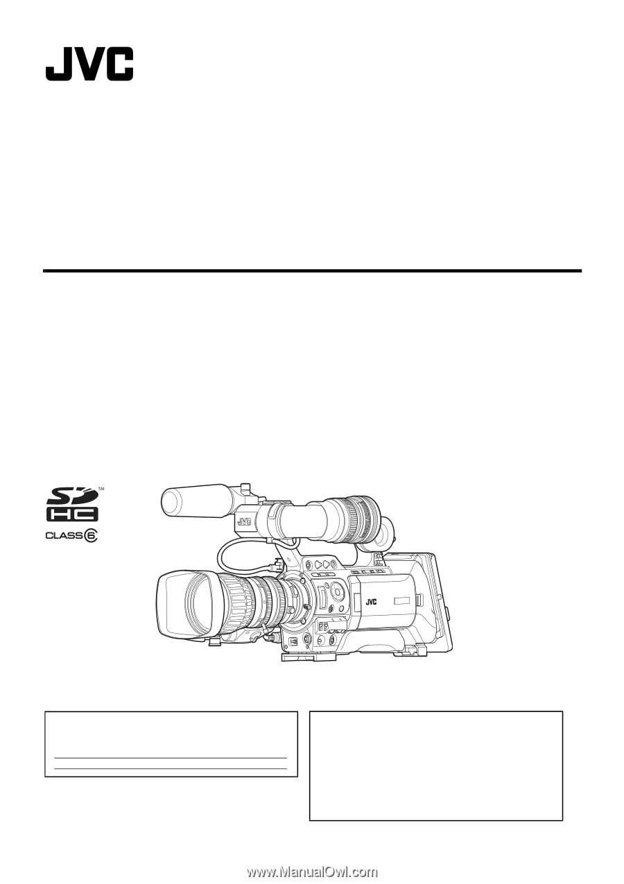
HD MEMORY CARD CAMERA RECORDER
GY-HM700U
GY-HM700CHU
GY-HM700E
GY-HM700CHE
INSTRUCTIONS
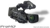
* The illustration shows the GY-HM700E with the supplied viewfinder, microphone and lens attached.
* GY-HM700CHU/GY-HM700CHE does not come with a lens.
For Customer Use:
Enter below the Serial No. which is located on the body.
Retain this information for future reference.
Model No.
GY-HM700U/GY-HM700CHU
Serial No.
Please read the following before getting started:
Thank you for purchasing this JVC product.
Before operating this unit, please read the instructions
carefully to ensure the best possible performance.
In this manual, each model number is described without the last letter
(U/E) which means the shipping destination. (U: for USA and Canada,
E: for Europe)
Only “U”models (GY-HM700CHU/GY-HM700U) have been evaluated by
UL.
LST0904-001B