JVC HM700U Instruction Manual
JVC HM700U - Camcorder - 1080p Manual
 |
View all JVC HM700U manuals
Add to My Manuals
Save this manual to your list of manuals |
JVC HM700U manual content summary:
- JVC HM700U | Instruction Manual - Page 1
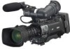
HD MEMORY CARD CAMERA RECORDER GY-HM700U INSTRUCTIONS GY-HM700CHU GY-HM700E GY-HM700CHE * The illustration shows the GY-HM700E with the supplied viewfinder, microphone and lens attached. * GY-HM700CHU/GY-HM700CHE does not come with a lens. For Customer Use: Enter below the Serial No. which - JVC HM700U | Instruction Manual - Page 2
appliance. Wall or shelf mounting should follow the manufacturer's instructions, and should use a mounting kit approved by the manufacturer power company. For appliance designed to operate from battery power, refer to the operating instructions. 10. For added protection for this product during - JVC HM700U | Instruction Manual - Page 3
servicing) instructions in the literature accompanying the appliance. INFORMATION: This equipment has been tested NOT APPROVED BY JVC COULD VOID USER'S AUTHORITY TO OPERATE THE EQUIPMENT. NOTE: The rating plate (serial REFERER A UN AGENT QUALIFIE EN CAS DE PROBLEME. Le symbole de l'éclair àl'intérieur - JVC HM700U | Instruction Manual - Page 4
best performance and furthermore for electromagnetic compatibility we recommend to use cables not exceeding the following lengths: Port [DC INPUT] [Y/VIDEO], [PB], [PR] [AUDIO INPUT 1/2] [AUDIO OUTPUT] [PHONES] [IEEE1394] (HD/DV) [HD/SD-SDI] [REMOTE] [LENS] [VF] [USB] Cable Exclusive Cable Coaxial - JVC HM700U | Instruction Manual - Page 5
V - JVC HM700U | Instruction Manual - Page 6
(Camera Mode Only 18 Menu Setting Screen 18 Alarm Display 18 Zebra Pattern Display 18 Preparations Attaching Accessories 19 Attaching the Zoom Lens 19 Attaching the Microphone (Supplied 19 Attaching the Viewfinder (Supplied 20 Power Supply 20 Using AC Power (DC IN Power 21 Using a Battery - JVC HM700U | Instruction Manual - Page 7
Unit Connection 115 List of Remote Control Unit Functions 116 Others Error Displays and Actions 118 Tally Lamps 119 Alarm Sound 119 Troubleshooting 120 Specifications 122 How to use this manual Ⅵ Symbols used Caution : Describes precautions concerning the operation of this product. Note - JVC HM700U | Instruction Manual - Page 8
used in this camera recorder. Support for Wide Variety of Output Supports industrial output such as HD-SDI output and IEEE1394 output. DV Transcode Output In consideration of the usage in SD environment, IEEE1394 output can also be encoded in DV format. Application Software Provided The [JVC ProHD - JVC HM700U | Instruction Manual - Page 9
, be sure to set the [POWER] switch to AOFFB in order to reduce power consumption. Batteries Ⅵ The following batteries can be used on this device. GY-HM700CHU/GY-HM700U : Dionic90 (Anton Bauer) GY-HM700CHE/GY-HM700E : Endura-7 (IDX) * Models with an E suffix are for the European market and will not - JVC HM700U | Instruction Manual - Page 10
the viewfinder when switching between the live video and playback images. Ⅵ Due to the characteristic of the viewfinder display device, colors may appear on the camera recorder that are played back for profit or public preview may infringe on the rights of the owner of the recordings. Do not use - JVC HM700U | Instruction Manual - Page 11
) the most recently recorded image using the Clip Review function. (A Page 52) Media Mode SD Card Mode IEEE1394 Mode Purple Green Orange When [Rec Mode] is set to AVariable FrameB, the operation mode indicator lights up in purple during Variable Frame REC in Camera mode. (A Page 56) This mode - JVC HM700U | Instruction Manual - Page 12
Page 44) G [DISPLAY] Display Button (A Page 29) H [CAM/MEDIA] Camera/Media Mode Selection Button (A Page 7) I [FULL AUTO] Full Auto Shooting (FAS) Switch (A Page 75) J Monitor Speaker (Cheek Pad) (A Page 26) K Shoe For mounting separately sold lights and accessories. L Microphone Holder Lock Knob - JVC HM700U | Instruction Manual - Page 13
X W W O V P Battery Mount (A Page 21) SDHC Focus Assist Button (A Page 35) Y Record Button Lock Switch Set the switch toward the lens to lock the [REC] trigger button Z. Memo : ● The [REC] trigger button (A Page 10) K at the side control panel on the right of the camera recorder is not locked - JVC HM700U | Instruction Manual - Page 14
Assist is activated. (A Page 35) C [FOCUS ASSIST] Focus Assist Button Press this button during shooting to display the focused area in either blue, red, or green. This enables easy and accurate focusing.(A Page 35) D [USER1], [USER2], [USER3] User Buttons (A Page 74) Use these buttons to switch - JVC HM700U | Instruction Manual - Page 15
operation mode. (A Page 7) Operation Mode Color Camera Mode Blue/Purple Media Mode (SD Card Mode) Green Media Mode (IEEE1394 Mode) Orange USB Mode Orange Memo : ● You can select whether to light up the indicator using [Mode LED] in the [Others] menu. (A Page 87) P [MONITOR] Audio Monitor - JVC HM700U | Instruction Manual - Page 16
use. A [HD/SD-SDI] HD/SD-SDI Output Terminal (BNC) (A Page 111) B [Y/VIDEO] Y/Composite Video Signal Output Terminal (BNC) (A Page 111) C [PB] PB Video Signal Output Terminal (BNC) (A Page 111) D [PR] PR Video Input audio signals are output during Camera mode. ● Playback audio signals are output - JVC HM700U | Instruction Manual - Page 17
. ● Check the instruction manual provided with the shoulder belt before using. B Accessory Connector (Connect to a option) C Battery Mounting Folder (A Page 21) The shape is different for GY-HM700CHU/GY-HM700U and GY-HM700CHE/GY-HM700E. * The above is the illustration for GY-HM700CHE/GY- HM700E. 13 - JVC HM700U | Instruction Manual - Page 18
] of [Switch Set...] in the [Camera Function] menu. (A Page 74) ( A Page 52 [Viewing Recorded Videos Immediately (Clip Review)]) Memo : ● When [LENS RET] of [Switch Set...] in the [Camera Function] menu is set to AFocus AssistB, this button functions as the Focus Assist button. (A Page 74) G Zoom - JVC HM700U | Instruction Manual - Page 19
KT14x4.4KRSJ (CANON) (GY-HM700U/GY-HM700E only) Battery Mount GY-HM700CHU/GY-HM700U : Gold Mount GY-HM700CHE/GY-HM700E : V Mount Standard Package Anton Bauer Anton Bauer Battery Charger Battery (Dionic90) For GY-HM700CHE/GY-HM700E* IDX Battery (Endura) IDX Battery Charger 1/2 Zoom Lens Mount - JVC HM700U | Instruction Manual - Page 20
video image on the LCD monitor and viewfinder screens during shooting. Besides camera and playback images, the following characters are displayed on the LCD monitor and viewfinder. Ⅵ Status screen (A Page 16) Ⅵ Auto White display *(A Page 18) Ⅵ Menu LOAD FILE RET CLIP REVIEW SKIN/SPOT SPOT METER - JVC HM700U | Instruction Manual - Page 21
STATUS 0B1B0) STATUS 0 Screen 1280x720 24p HQ [DISPLAY] Button 1 Set [LCD + VF] in the [LCD/VF] menu to AOnB. (A Page 82). 2 Press the [DISPLAY] button while the LCD screen is displayed. The display switches between the same display as the viewfinder and the enlarged display with every press of the - JVC HM700U | Instruction Manual - Page 22
that indicate the luminance level of the video image can be displayed on this camera recorder. You can set the luminance levels for displaying the two types of zebra patterns. ( A Page 50 [Setting Zebra Pattern]) Zebra Pattern [Main Menu] Screen Memo : ● Use the [ZEBRA ON/OFF] switch in front - JVC HM700U | Instruction Manual - Page 23
Attaching Accessories Attaching the Zoom Lens (Supplied with GY-HM700U/GY-HM700E only) Hole 13 Pin REC 2 Clamp 4 may drop or the back focus may be out of alignment. ● When attaching or removing the zoom lens, set the [POWER] switch of the camera recorder to AOFFB. Attaching the - JVC HM700U | Instruction Manual - Page 24
ring to secure the position of the viewfinder. Slide Lock Ring 2 Power Supply To use this camera recorder, you can attach a battery pack or connect an AC adapter to it. ( A Page 21 [Using a Battery Pack]) ( A Page 21 [Using AC Power (DC IN Power)]) Note : ● Set the [POWER] switch to AOFFB before - JVC HM700U | Instruction Manual - Page 25
the European market and will not employ the UL Listing mark. Note : ● Make use of the recommended batteries. Heavy batteries may fall off if not used correctly. ● See the battery instruction manual on how to charge the battery. [DC INPUT] DC Cable DC OUTPUT AC Adapter 2 Set the [POWER] switch of - JVC HM700U | Instruction Manual - Page 26
and insert straight. Guide Hole (x3) Release Lever Guide Pins Attaching the Battery (GY-HM700CHE/GYHM700E) Use the Endura-7 (IDX) battery. 1 Attach the battery. Face the terminal downward and attach the V mount of the battery onto the V mount attachment bracket of the camera recorder. V Mount - JVC HM700U | Instruction Manual - Page 27
and menu screens. If the battery or supplied voltage from the AC adapter is low, a warning will be displayed in red. Note : ● If the battery in use is not a recommended one, the battery mark which indicates the battery level may not appear. Ⅵ Status screen ( A Page 90 [Status Screen in Camera Mode - JVC HM700U | Instruction Manual - Page 28
on the operation mode display area of the LCD monitor and viewfinder. Press the [REC] trigger button to start recording. Memo : ● Playback of SDHC card is not possible in Camera mode. However, you can use the Clip Review function to check the most recently recorded video clip. (A Page 52) Ⅵ Media - JVC HM700U | Instruction Manual - Page 29
battery is turned on again after being fully discharged. All operations are disabled until initial settings are complete. [MENU date/time data can be displayed on the LCD monitor and Initial Setting] screen appears. Ⅵ For GY-HM700CHU/GY-HM700U 2 Set the date and time. GY-HM700CHE/GY-HM700E 25 - JVC HM700U | Instruction Manual - Page 30
Display Style You can change the display style of the date/time on the menu. Memo : ● To perform the settings while looking at the monitor screen connected to the video knob at the side control panel on the right of the camera recorder. Various warning alarm tones may also be output repeatedly. - JVC HM700U | Instruction Manual - Page 31
). 2 Set the zoom mode switch to AMANU.B (manual). 3 Turn to open the iris ring. Adjust the lighting such that the optimum image level can be obtained. 4 Turn the zoom lever to set the lens to the maximum telephoto position. 5 Turn the focus ring to adjust the focus of the object. 6 Set the lens to - JVC HM700U | Instruction Manual - Page 32
PEAKING] Knob [VF BRIGHT] Knob Eyepiece Focus Ring Eyepiece Slide Lock Ring Eyepiece Lock Ring Note : ● A high-definition viewfinder is used on this camera recorder in order to provide an accurate focusing environment. Due to the characteristic of the display device, colors may appear on the images - JVC HM700U | Instruction Manual - Page 33
Use the [VF PEAKING] knob to adjust the contour of the viewfinder screen. T Screen display during adjustment ( A Page 28 [Adjusting contour and brightness]) Displaying in black and white (A Page 82) You can display the viewfinder screen in black and white. Select [Main Menu] B [LCD/VF] B [VF Display - JVC HM700U | Instruction Manual - Page 34
and warning. The operation changes according to the menu settings. When the battery or remaining space on the SDHC card is low, the lamps blink. (Camera mode only) * Set using [Tally System]/[Front Tally]/[Back Tally] in the [Main Menu]B[Others...] menu. (A Page 87) Front Tally Lamp Back Tally - JVC HM700U | Instruction Manual - Page 35
of slot A and B. Lamp Lights up in red Lights up in green Light goes out Slot Status Inserted SDHC card is being accessed. (writing/reading data) Do not turn off the power of the camera recorder or remove the SDHC card. On standby. Inserted SDHC card can be used for recording or playback. ● SDHC - JVC HM700U | Instruction Manual - Page 36
if you press the button. 5 Formatting starts. Formatting (Initializing) SDHC Cards When the following cards are inserted, AFormatting RequiredB appears. Format the card using the camera recorder menu. ● Unformatted SDHC cards ● SDHC cards formatted under different specifications * For details of - JVC HM700U | Instruction Manual - Page 37
...] menu screen. Estimated Recordable Time of SDHC Cards The estimated recordable time is only a guide. Differences may occur depending on the SDHC card in use and the battery condition. ( A Page 71 [Camera Resolution]) ( A Page 71 [Frame & Bit Rate]) QuickTime/MP4 Camera Resolution Bit Rate - JVC HM700U | Instruction Manual - Page 38
Supply battery or AC adapter power to the camera used to start/stop recording by default. ● During recording, the front and back tally lamps light up in red. Memo : ● Tally lamps can be turned off with [Front Tally]/[Back Tally] in the [Others] menu. (A Page 87) ● To separately control this camera - JVC HM700U | Instruction Manual - Page 39
the [RET] button on the lens You can assign the Focus Assist function to the [RET] button on the lens. * Set [Main Menu]B[Camera Function]B[Switch Set...]B[LENS RET] to AFocus AssistB. (A Page 74) ⅥRecorded Clips This camera recorder uses FAT32 File System. As such, recorded materials may be split - JVC HM700U | Instruction Manual - Page 40
) 50i(SP) HDV compatible 1920x1080 60i(HQ) Full HD 30p(HQ) Full HD 50i(HQ) Full HD 25p(HQ) Full HD 24p(HQ) Full HD File Format MP4 Record Format Camera Resolution Horizontal×Line 1280x720 Frame & Bit Rate 60p(HQ) 60p(SP) 30p(HQ) 30p(SP) 24p(HQ) 24p(SP) 50p(HQ) 50p(SP) 25p(HQ) 25p - JVC HM700U | Instruction Manual - Page 41
/darker) of the auto iris. You can also use the menu to set the tracking sensitivity of the auto iris. (A Page 73) Fixed Gain Mode (Manual Gain Switching) You can select the gain of the video amplifier using the [GAIN] switch on the camera recorder. The default positions of the switch are as - JVC HM700U | Instruction Manual - Page 42
[Shutter] in the [Camera Function] menu. AStepB is set at factory default. (A Page 73) ⅥSwitching Shutter Speed When shutter is ON, use the [SHUTTER] switch (JK) to set the shutter speed. Shutter speed differs according to the video format and variable frame rate settings. Ⅵ During modes other - JVC HM700U | Instruction Manual - Page 43
displayed in angle (DEG). ( A Page 71 [Frame & Bit Rate]) ( A Page 85 [Shutter Disp.]) Automatic Shutter Mode (Automatic Shutter Adjustment) Set the [FULL AUTO] switch on the camera disabled. Memo : ● When [Shutter] in the [Camera Function]B[FULL AUTO...] menu is set to ASW SetB, you can switch the - JVC HM700U | Instruction Manual - Page 44
USER1], [USER2], or [USER3] buttons using [Switch Set...] in the [Camera Function] menu. (A Page 74) ⅥMemory A Mode the lighting (A Page 43). 3 Set the [WHT.BAL.] switch to AAB or ABB. 4 Locate a place with similar lighting conditions Frame AUTO WHITE A OK Result Display Note : ● Do not use - JVC HM700U | Instruction Manual - Page 45
is not suitable. Use another white object and adjust the white balance again. ERROR : LOW LIGHT Insufficient illumination. Displayed when the lighting is dark. Increase the lighting and adjust the white balance again. ERROR : OVER LIGHT Excessive illumination. Displayed when the lighting is too - JVC HM700U | Instruction Manual - Page 46
] and press the Set button (R) to return to the [White Balance] menu. Top CD 1 Fill the monitor screen with a pattern box of uniform light source or white (plain) paper shone with uniform lighting. 2 Set the control of the camera lens as follows. ASet the aperture to F4 or more such that the iris - JVC HM700U | Instruction Manual - Page 47
for indoor and dark outdoor environments. Memo : ● The display of the ND filter position is set to AOffB by default. To display the position of the ND filter, set [Filter] in the [LCD/VF]B[Status Display...] menu to AOnB. (A Page 84) ● It is recommended to use the ND filter to set the lens aperture - JVC HM700U | Instruction Manual - Page 48
switch to AMANUALB for the channel to manually adjust the recording level. 2 Turn the corresponding [AUDIO LEVEL CH-1/CH-2] adjustment knob to adjust the level. Adjust such that the audio level meter does not light up at -2 dB even for loud sounds. 1280x720 30/24 fps 24p HQ 00:00:00:00 A 100min - JVC HM700U | Instruction Manual - Page 49
on the camera recorder even if the [FULL AUTO] switch is set to AONB. (A Page 75) ⅥUsing Stereo Type Earphone Jack When a stereo type earphone jack is connected, perform the following setting to output stereo sound. 1 Set the [MONITOR SELECT] switch to ABOTHB. 2 Set [Main Menu]B[A/V Out]B[Audio - JVC HM700U | Instruction Manual - Page 50
code Char.] in the [A/V or user's bit is displayed Out] menu is set to during the following status display and information AOnB, time code or user's bit is display mode of the LCD displayed in the screen. respective video Ⅵ STATUS 1 Screen in Camera mode output images during the LCD/VF - JVC HM700U | Instruction Manual - Page 51
starts to operate in run mode from the preset time in the time code generator. 2 Select the framing mode for the time code generator (only when the frame rate setting is A60B or A30B). Set using [Main Menu]B[TC/UB]B[Drop]. (A Page 82) [Drop] [Non Drop] Sets the run mode of the time code generator - JVC HM700U | Instruction Manual - Page 52
[CANCEL] Button Memo : ● Settings cannot be made in the following cases. ● [TC GENE.] switch is set to AREGENB. ● Menu screen is displayed. ● The camera recorder is not in Camera mode. ⅥRequired Settings Before Preset (A Page 47) ● Set the [TC DISPLAY] switch to ATCB. ● Set the [TC GENE.] switch to - JVC HM700U | Instruction Manual - Page 53
2 Set the time code (hour, minute, second, frame). Use the cross-shaped button (H, I) to place the cursor at Opening the Menu Memo : ● Settings cannot be made in the following cases. ● [TC GENE.] switch is set to AREGENB. ● Menu screen is displayed. ● The camera recorder is not in Camera mode. Ⅵ - JVC HM700U | Instruction Manual - Page 54
the specified range of two zebra patterns overlaps, the two zebra patterns overlap and are displayed in a grid. 3 Display the zebra pattern. Set the [ZEBRA ON/OFF] switch in front of the camera recorder to AONB to display the zebra pattern at the specified range. Zebra Pattern [ZEBRA ON/OFF] Switch - JVC HM700U | Instruction Manual - Page 55
Spot Meter The brightness of the object during shooting is displayed. This function is useful when setting video or stage lighting or when specifying camera exposure. A cursor indicating the location and the brightness (%) of that location are displayed in the images shown on the LCD monitor and - JVC HM700U | Instruction Manual - Page 56
. You can check (review) the last recorded video clip on the screen. However, the video clip cannot be played back if the settings of the camera recorder are different from the video format (Camera Resolution/Frame & Bit Rate) of the clip. (A Page 71) Memo : ● To use this function, assign AClip - JVC HM700U | Instruction Manual - Page 57
is unavailable when Clip Continuous REC is paused (STBYC , red text) . To operate Clip Review, use the [CANCEL] button to set to ASTBYCB (white text) first. (A Page 55) ● Clip Review is unavailable when the camera recorder is connected to an external equipment and the equipment is in recording state - JVC HM700U | Instruction Manual - Page 58
methods are available in this camera recorder. They are Pre REC, Clip Continuous REC, and Variable Frame REC. Select the mode from [Rec Mode] in the [Record Set] menu. * Set using [Main Menu]B[Record Set]B[Rec Mode]. (A Page 71) Pre REC This mode allows you to start video and audio recording about - JVC HM700U | Instruction Manual - Page 59
changes to ARECCBBASTBYCB (red text). ● The card slot status indicator remains lighted in red. Memo : ● When the [CANCEL] button is pressed while the camera recorder is paused (STBYC), the display changes to ASTBYCB (red text) BASTBYCB (blinking red text) BASTBYCB (white text). A AclipB is generated - JVC HM700U | Instruction Manual - Page 60
videos. Using different frame rate settings for recording and playback., videos captured at normal speed can be played back more smoothly than those in low or high speed playback. Variable Frame REC is only enabled under the following situations. ● [Camera Resolution] in the [Record Format] menu - JVC HM700U | Instruction Manual - Page 61
camera recorder to operate the thumbnail screen. C B D A E Thumbnail Screen The thumbnail screen is available in "No Detailed Properties (4x3 thumbnails)" and "Detailed Properties (4x1 thumbnails)" displays. Use the thumbnail menu [Detailed Properties] to switch display. (A Page 61) The first frame - JVC HM700U | Instruction Manual - Page 62
]B[File Format] of the [Main Menu] screen. (A Page 71) Name D Video Format Description Displays the video format (Camera Resolution/Frame Rate) that allows playback and thumbnail display. Available in 4 types: [1080/60i, 30p, 24p], [1080/50i, 25p], [720/60p, 30p, 24p], and [720/50p, 25p]. Clips - JVC HM700U | Instruction Manual - Page 63
Displays clip information (properties). A B C J Operation Guide A OK Mark Clip is appended with OK mark. Memo : ● Clips appended with OK marks cannot be deleted on the camera the SDHC card is locked. (Displayed in gray) Deletes the OK mark from the selected clip. This is displayed when an OK - JVC HM700U | Instruction Manual - Page 64
C Detailed Properties D Operation Guide Description Shows the detailed properties of the selected clip. The following information is displayed. File Format : File format Clip Name : Clip name Resolution : Image size Frame Rate : Frame rate Bit Rate : Bit rate Audio : Audio format Start - JVC HM700U | Instruction Manual - Page 65
Back Use the operation buttons on the side control panel of the camera recorder to play back. A B C Thumbnail Menu Press the [MENU] button during thumbnail display to display the thumbnail menu. Press the [MENU] button during menu display to cancel the settings and exit the menu. Thumbnail Menu - JVC HM700U | Instruction Manual - Page 66
screen to confirm deletion appears. 3 Use the cross-shaped button (JK) to select [Delete] and press the Set button (R) Deleting starts. 3 Deleting One Clip You can delete a selected clip with any of the following operations. A Press [USER2] button when menu is not displayed. B Perform [Delete Clip - JVC HM700U | Instruction Manual - Page 67
4 Use the cross-shaped button (JK) to select [Delete] and press the Set button (R) Deleting All Clips Deletes all clips that are displayed. 1 Press the [MENU] button. The thumbnail menu screen appears. 2 Select [Delete Clip...]B[All Clips] in the menu. A screen to confirm deletion appears. 3 - JVC HM700U | Instruction Manual - Page 68
deleted, thus protecting the important clips. When the camera recorder is in Media mode (SD Card mode), [OK] marks after shooting. [USER1] Button [MENU] Button Set Button (R) CrossShaped Button (JKHI) [ card is set ( is displayed). ● AOK Mark Added...B is displayed when changing marks and other - JVC HM700U | Instruction Manual - Page 69
Pause Screen 1 Press the [USER1] button when playing back a clip appended with OK mark. The OK mark is deleted. 1 Memo : ● The [USER1] button is disabled (displayed in gray) and OK marks cannot be deleted when the write-protect switch of the SDHC card is set ( is - JVC HM700U | Instruction Manual - Page 70
level. Title of the currently displayed menu. : Ample battery power. : Slightly reduced battery power. : Low battery power. : Empty battery power. (Blinks in red) : External power supply connected. Memo : ● If the battery in use is not a recommended one, the battery mark which indicates the - JVC HM700U | Instruction Manual - Page 71
Menu item to be changed. A list of setting values C appears in a pop-up. Guide for the current operation buttons. A pop-up displaying The cursor can be moved using the arrow keys F. Use the cross-shaped button (JKHI on the side control panel of the camera recorder to abort character input and return - JVC HM700U | Instruction Manual - Page 72
Menu Display and Detailed Settings Menu Screen Hierarchical Chart Main Menu... (A Page 70) Record Set...(A Page 71) Record Format(A Page 71) Rec Mode (A Page 71) Clip Set (A Page 72) File Format Camera Resolution Frame & Bit Rate Clip Name Prefix Reset Clip Number Audio Set (A Page 72) Input1 - JVC HM700U | Instruction Manual - Page 73
83) Marker Setting... (A Page 84) Status Display... (A Page 84) LCD + VF VF Display LCD Mirror Mode Output Terminal Down Convert Set Up HD/SD-SDI Out Analog Out Char. SDI Out Char ) can be found at the end of each menu item. Select [Back] and press the Set button to return to the previous level. 69 - JVC HM700U | Instruction Manual - Page 74
Screen Some menus cannot be set depending on the operating mode or status of the camera. These items are displayed in gray, and they cannot be selected. Item Function Record Set Menu screen for specifying video or audio settings during shooting and playback. The cursor does not move to this - JVC HM700U | Instruction Manual - Page 75
For setting the recording [Frame Rate] when [Rec Mode] is set to [Variable Frame]. Memo : ● When [AE LEVEL] in the [Main Menu]B[Camera Function]B[Switch Set...] menu is set to AAE LEVEL/VFRB, you can use the cross-shaped button (HI) to select the frame rate during Variable Frame REC. In modes other - JVC HM700U | Instruction Manual - Page 76
Menu Display and Detailed Settings Record Set Menu (continued) Clip Set Menu the smallest available number is used after reset. Example:If the 12dB -20dB Audio Limiter On Off Test Tone On Off Function For setting whether to cut the low frequencies of the audio input signals (low-cut) when the - JVC HM700U | Instruction Manual - Page 77
AUTO] switch on the camera recorder is set to AONB, and [Bars] in the [FULL AUTO...] menu is set to AOffB, adjusted using the the cross-shaped button (H, I) on the right of the camera recorder. low speed. Off : Deactivates the Smooth Trans function. For specifying the switch settings of the camera - JVC HM700U | Instruction Manual - Page 78
B.Compress4 B.Compress5 Assigns the functions of [Stretch Level] and [Compress Level] under [Black Toe] in the [Camera Process] menu. (A Page 76) LENS RET Clip Review OK Mark Focus Assist Clip Review Last 5 sec Top 5 sec CLIP For assigning a function to the [RET] button on the lens. This - JVC HM700U | Instruction Manual - Page 79
Frame REC, and operates as the AE LEVEL setting button in other cases. (A Page 56) AE LEVEL : Operates as the AE LEVEL setting button at all times. Disable : Disables the button. FULL AUTO... Item This is used to set specific functions to the auto mode when the [FULL AUTO] switch of the camera - JVC HM700U | Instruction Manual - Page 80
Menu Display and Detailed Settings Camera Process Menu specifying the AKneeB operation, which compresses video signals beyond a certain level to show manually. Manual : Enables manual adjustment of the knee point (starting point of knee operation) using the light intensity. Memo : ● When [Knee] - JVC HM700U | Instruction Manual - Page 81
when the system in use limits Y output signals gamma curve that focuses on the gradation displayed in black-and-white when this is set to AOffB. DNR On Off For setting the DNR (Digital Noise Reduction) function. The S/N ratio of the video Camera Process...] menu to their default settings. 77 - JVC HM700U | Instruction Manual - Page 82
Menu Display and Detailed Settings Camera Process Menu (continued) Detail/Adjust... Item * Default values are indicated in bold characters. Item V/H Balance H Frequency V Frequency Setting Values H-Max, 4 to1, Normal, -1 to -4, H-Min High Middle Low High Low of softening) using the Skin Detail - JVC HM700U | Instruction Manual - Page 83
Strengthens the red. Decrease the number : Weakens the red. Memo : ● This item is selectable when the [WHT.BAL.] selection switch on the right of the camera recorder is set to AAB or ABB. When APRESETB is set, this item appears as A---B and cannot be selected. ● Different values can be specified for - JVC HM700U | Instruction Manual - Page 84
Menu Display and Detailed Settings Camera Process Menu display, and the displays for Bars, Zebra, markers (Aspect Marker/Safety Zone/Center Mark), Focus Assist mode, and AB & WB mode in the [VF Display] menu Item This item is used to adjust [Color Matrix yellow level of the video toward red. Increase - JVC HM700U | Instruction Manual - Page 85
the cyan component of green/cyan. Decrease the number : Reduces the cyan component of green/cyan. For adjusting the cyan/blue level of the video toward cyan. Increase the number : Enhances the cyan component of cyan/blue. Decrease the number : Reduces the cyan component of cyan/blue. For adjusting - JVC HM700U | Instruction Manual - Page 86
. Drop : Internal time code generator works in the drop-frame mode. Use this setting when placing emphasis on the recording time. Memo : ● This item can be set only when the frame rate of [Frame & Bit Rate] in the [Record Set...]B[Record Format] menu is set to A60pB, A30pB, or A60iB. When other - JVC HM700U | Instruction Manual - Page 87
Displays the focused area in blue. Green : Displays the focused area in green. Red : Displays the focused area in red. For setting the display range of the focused area when Focus Assist is activated. High : Sets the display range wider than Middle. Middle : Sets the display range to standard. Low - JVC HM700U | Instruction Manual - Page 88
: Hides the center mark. *1: Regardless of the setting, the marker does not appear during Clip Review and in Media mode. Status Display... Item This menu is used to set the status displays on the LCD monitor and viewfinder screens. Item Setting Values Function F.No/Iris Indicator F.No+Iris - JVC HM700U | Instruction Manual - Page 89
degrees in the same way as film cameras. SEC : Displays the shutter speed in seconds. Memo : ● ADEGB is selectable only when [Frame & Bit Rate] is set to A24p(SP)B, A24p(HQ)B, A25p(SP)B, or A25p(HQ)B. When [Frame & Bit Rate] is set to other values, the shutter display setting is fixed at ASECB and - JVC HM700U | Instruction Manual - Page 90
is used as a flag to determine valid video signals. Therefore, accurate values will not be output. Analog Out Char. On Off For selecting whether to display status and menu characters on the screen output from the [Y/ VIDEO]/[PB]/[PR] video signal output terminal (BNC) on the side of the camera - JVC HM700U | Instruction Manual - Page 91
Outputs alarm tone at a medium volume level. Low : Outputs alarm tone at a low volume level. Off : Alarm tone is not output. For specifying the illumination settings of the operation mode indicator on the side control panel of the camera recorder. On : Lights up as below according to the operation - JVC HM700U | Instruction Manual - Page 92
recording in Camera mode, during Clip Review, and in Media mode. Date/Time ^ For setting the year, month, day, hour, and minute. Memo : ● The display order of the date (year, month, and day) follows the [Date Style] setting in the [Status Display...] menu. However, the 24-hour format is used for - JVC HM700U | Instruction Manual - Page 93
to be restored. However, it is not selectable when recording in Camera mode and during Clip Review. Setup File Manage Menu Menu settings and button operations ([SHUTTER], [AE LEVEL], etc.) can be saved. It is useful to save settings according to different shooting conditions. Item Setting Values - JVC HM700U | Instruction Manual - Page 94
(displayed in red) REC : Recording : Clip Continuous recording pause REVIEW : Clip Review (A Manual White Balance mode (only during control using the remote control) Appears when [Black Toe] in the [Camera Process] menu is set to a value other than ANormalB. (A Page 76) B+1 to B+5 : Displays - JVC HM700U | Instruction Manual - Page 95
locked SLOT SWITCHED * (* : A, B) Active SDHC slot is switched automatically or using the [SLOT SELECT] button in Camera mode. TRIGGER TO HD, TRIGGER TO DV Recording command is sent out from the [IEEE1394] terminal FRAME RATE rrrr/pp fps (rrrr: recording frame rate, pp: playback frame rate - JVC HM700U | Instruction Manual - Page 96
the video image resolution. (1920ן1080, 1440ן1080, 1280ן720) B Frame Rate/Bit Rate Displays the frame rate and bit rate in pairs. (60p HQ, 30p HQ, 60i HQ, 60p SP, 30p SP, 60i SP, 50p HQ, 25p HQ, 50i HQ, 50p SP, 25p SP, 50i SP, 24p HQ, 24p SP) C OK Mark Appears when an OK mark is added - JVC HM700U | Instruction Manual - Page 97
external device. For details, refer to the instruction manual of the corresponding external device. Memo : ● Only warnings are displayed in the STATUS 0 and STATUS 4 sScreens. J Time Code (TC)/ User's Bit (UB) Displays the time code (hour:minute:second:frame) or user's bit data. Example: Time code - JVC HM700U | Instruction Manual - Page 98
Screen in Camera Mode (continued) STATUS 2 Screen CAMERA INFORMATION SETUP not supported (not of class 6 type). A : Write-protect switch of SDHC card is set. Displays the ] in the menu is set to A1PatternB, ZEBRA2 appears as A---B. (A Page 83) F Subname of Setup File Displays the subname of - JVC HM700U | Instruction Manual - Page 99
1 to 5 Displays the setting status of the [RET] button on the lens. (CLIP REVIEW, FOCUS ASSIST, OK MARK) Displays the setting status of DISABLE, AE LEVEL, AE LEVEL/VFR) STATUS 4 Screen This screen displays the event. It is also used to display warnings only. 30/24 fps *0 DD 20 min *1 A 1min - JVC HM700U | Instruction Manual - Page 100
the video image resolution. (1920ן1080, 1440ן1080, 1280ן720) Displays the frame rate and bit rate in pairs. (60p HQ, 30p HQ, 60i HQ, 60p SP, 30p SP, 60i SP, 50p HQ, 25p HQ, 50i HQ, 50p SP, 25p SP, 50i SP, 24p HQ, 24p SP) Displays the media slot (A or B) of the currently played clip. A key - JVC HM700U | Instruction Manual - Page 101
AC adapter is low, the voltage value will be displayed in red as a warning. 12.3V 200min Currently powered by a battery. When the battery power runs out, the battery mark appears hollow, and ARESB is displayed. 30% RES Memo : ● The display on the right can be set using [Battery Info] of [Status - JVC HM700U | Instruction Manual - Page 102
a warning is displayed [Voltage/Remaining Battery Power] (A Page 98 ) STATUS 2 Screen B 1280x720 A 24p HQ [Event/Warning Display Area] (A Page 91 ) 282min D C Item A Frame Rate/Bit Rate B Resolution Display C Audio Level Meter Description Displays the frame rate and bit rate in pairs. (60p - JVC HM700U | Instruction Manual - Page 103
● The display on the right can be set using [Battery Info] of [Status Display...] in the [LCD/ VF] menu. (A Page 85) I Operation of External Device J Time Code (TC)/ User's Bit (UB) Displays the operating status of the connected external device. For details, refer to the instruction manual of the - JVC HM700U | Instruction Manual - Page 104
You can turn ON/OFF the safety zone and center mark displays as shown below using the [Aspect Ratio], [Safety Zone] and [Center Mark] settings of [Marker Setting...] in the [LCD/VF] menu. (A Page 84) [Aspect Marker] Display Ⅵ When [Aspect Ratio] = A4:3B [Line] [Halftone] [Line+Halftone] [Aspect - JVC HM700U | Instruction Manual - Page 105
Ⅵ When [Aspect Ratio] = A4:3B, [Aspect Marker] = AHalftoneB, and [Center Mark] = AOnB [Off] [95%] [93%] [90%] [80%] [88%] [Center Mark] Display Ⅵ When [Aspect Ratio] = A4:3B, [Aspect Marker] = AHalftoneB, and [Safety Zone] = A80%B [Off] [On] Ⅵ When [Aspect Ratio] = A4:3B, [Aspect Marker - JVC HM700U | Instruction Manual - Page 106
enhancement of video signals for only the skin areas so as to produce a smoother skin tone. Preparations Before Using the Skin Detail Function (Skin Adjust Function) 1 Adjust the white balance. (A Page 40) 2 Display the [Skin Color Adjust] screen. (A Page 78) ● Select [Main Menu...]B[Camera Process - JVC HM700U | Instruction Manual - Page 107
displayed in skin tone. (A Page 77) ● When [SKIN A./SPOT M.] of [Switch Set...] in the [Camera Function] menu screen is set to ASpot MeterB, the hue area cannot be checked using select whether to output the reference audio signals using [Test Tone] in the [Audio Set] menu. (A Page 72) ● Color bars - JVC HM700U | Instruction Manual - Page 108
ACinema SubduedB in [Color Matrix] can be stored individually. (A Page 77) 1 Select [Color Matrix] or [Adjust...] in the [Camera Process...] menu. (A Page 80) 2 Adjust the saturation. ● Use the cross-shaped button (JK) to select a value. ● The correction range (gray area in the chart below) for each - JVC HM700U | Instruction Manual - Page 109
B&Mg B Level R I Increase the value: Mg Corrected Y increases B&Mg Mg Level YI G R I B Cy Mg Decrease the value: Corrected Y decreases Increase the value: Corrected Y decreases YI G Decrease the value: B Corrected Y increases Cy 3 Adjust Yl&G Mask Range. Adjusting [Yl&G Yl Level] and [Yl&G - JVC HM700U | Instruction Manual - Page 110
of contrast. 1 Adjust [Black Toe] in the [Camera Process...] menu according to the captured video signals. 2 Set the luminance point (Point Level) ● Set the amount to stretch or compress the dark areas in the image using [Stretch Level] or [Compress Level]. ● The amount of stretch or compression - JVC HM700U | Instruction Manual - Page 111
according to the tone of the GY-HD series. [Camera Resolution] is set to A1280x720B, and [Frame & Bit Rate] is set to A50p(HQ)B. [CINEMA 1080/24p]: Setting that is suited for movie-like video shooting. [Camera Resolution] is set to A1920x1080B, and [Frame & Bit Rate] is set to A24p(HQ)B. Picture - JVC HM700U | Instruction Manual - Page 112
be newly saved (or overwritten) using the cross-shaped button (J, K), and press the Set button. Cursor [Store File...] Menu Screen Memo : ● Files cannot be written in the following cases. (Displayed in gray, selection disabled) ● The inserted SDHC card is not supported (those other than SDHC Class - JVC HM700U | Instruction Manual - Page 113
Error!B message (indicated in red frame) appears for several seconds, after which the previous screen is displayed. 8 Saving is complete. After existing files are displayed. 4 Select the file to load using the cross-shaped button (J, K), and press the Set button. Cursor [Load File] Menu Screen Memo - JVC HM700U | Instruction Manual - Page 114
camera recorder. Connect the external monitor to the [Y/VIDEO] output terminal for composite signals, or to [Y/VIDEO], [PB], and [PR] video signal output terminals for component signals. * Select the output signal using [Output Terminal] in the [A/V Out] menu. (A Page 86) * To display menu screens - JVC HM700U | Instruction Manual - Page 115
[PHONES] Terminal Audio output from the [PHONES] terminal can be selected using [Audio Monitor] in the [A/V Out] menu (A Page 87) as well as the [MONITOR SELECT] switch on the camera recorder. The different combinations of settings that are output from the [PHONES] terminal and monitor speaker are - JVC HM700U | Instruction Manual - Page 116
Device Signal Flow 2 Set the camera recorder to Camera mode. 3 Set the recording video format. Note : ● Make sure that the SP mode is selected for the [Frame & Bit Rate] setting. 4 Perform the following settings on the camera recorder (master device). ASet the [HD/DV] IEEE1394 terminal mode switch - JVC HM700U | Instruction Manual - Page 117
camera recorder can be stream output during editing using a non-linear editing system. ⅥLoading to a Non-linear Editing System in Play Mode 1 Perform the following settings on the camera recorder. A Set the [HD . For details, refer to the instruction manual of the non-linear editing system. 8 Loading - JVC HM700U | Instruction Manual - Page 118
files using the (JVC ProHD Clip Manager) PC application software in the bundled CDROM. ● For details on how to install the application software, refer to the [User's Guide] of the [SxS Memory Card Device Driver Software] inside the bundled CD-ROM. 1 Connect the camera recorder to the PC using - JVC HM700U | Instruction Manual - Page 119
of the camera recorder. ● Focus and zoom operations cannot be performed using the remote control. ● The shutter speed may vary slightly from the value displayed on the camera recorder. ● Shutter speed when the frame rate of [Frame & Bit Rate] is A24pB When the frame rate of the camera recorder is - JVC HM700U | Instruction Manual - Page 120
Unit Iris F Value Display LEVEL 3: Available -: MANUAL, AUTO 3 AUTO IRIS LEVEL, MANUAL 3 IRIS LEVEL ZOOM WIDE, STOP, TELE - FOCUS NEAR, STOP, FAR - *1 : Only when the [Frame & Bit Rate] of the camera recorder is A60B, A30B, or A24B. *2 : Only when the [Frame & Bit Rate] of the camera - JVC HM700U | Instruction Manual - Page 121
1/120 *2 3 1/250 3 1/500 3 1/1000 3 1/2000 3 EEI 3 MASTER BLACK 3 IRIS MANUAL, AUTO 3 MANUAL LEVEL 3 AI LEVEL 3 *1 : Only when the [Frame & Bit Rate] of the camera recorder is A60B, A30B, or A24B. *2 : Only when the [Frame & Bit Rate] of the camera recorder is A50B or A25B. 117 - JVC HM700U | Instruction Manual - Page 122
are output as follows according to the alarm status. Memo : ● This camera recorder makes use of a microcomputer. Noise interference from external sources may prevent it from functioning properly. When this occurs, turn off and on the power of the camera recorder again. Error Display Status Screen - JVC HM700U | Instruction Manual - Page 123
(Error displays for about 7 seconds) When making use of a connected external device, turn on the power supply on the connected device. ● Video format of the file for Clip Review is different from the [Frame & Bit Rate] setting of the camera recorder. Set [Camera Resolution] and [Frame & Bit Rate - JVC HM700U | Instruction Manual - Page 124
clip a playable clip? Playback is not possible if the clip has a different video format setting. ● Is the camera recorder set to the IEEE1394 Input mode? (Operation mode indicator: Lights up in orange) ● Is the [HD/DV] IEEE1394 terminal mode switch correctly set? ● Is the currently played clip - JVC HM700U | Instruction Manual - Page 125
● The date and time are only displayed on the STATUS 2 and STATUS 3 Screens in the Camera mode (during shooting). (A Page 94)(A Page 95) ● Is [Output Terminal] in the [A/V Out...] menu correctly set? (A Page 86) ● Is the LCD used with [LCD + VF] in the [LCD/VF] menu set to AOffB? (A Page 82) ● Is - JVC HM700U | Instruction Manual - Page 126
Lens Section (GY-HM700U/GY-HM700E only) Lens Filter diameter : Canon F/1.6, 14x, f = 4.4-61.6 mm (35 mm conversion: 32-448 mm) : 82 mm 122 Storage Section Supported media Slots : SDHC (Class 6) : x2 Video/Audio Recording time : Video HQ mode SP mode : Audio Video frame rate : NTSC settings - JVC HM700U | Instruction Manual - Page 127
Accessories Microphone 1 Lens (GY-HM700U/GY-HM700E only) 1 Instructions 1 CD-ROM 1 Warranty Card (GY-HM700CHU/GY-HM700U only) 1 Dimensional Outline Drawing Ⅵ (Unit: mm) 40 (VF MOVE) 90 95 (VF MOVE) 56 133 59.8 44.6 108.5 291 (for ANTON BATTERY) (166) 231 242.3 82.3 225 (82 - JVC HM700U | Instruction Manual - Page 128
LST0904-001A GY-HM700U/GY-HM700CHU/ GY-HM700E/GY-HM700CHE HD MEMORY CARD CAMERA RECORDER 2009 Victor Company of Japan, Limited
-
 1
1 -
 2
2 -
 3
3 -
 4
4 -
 5
5 -
 6
6 -
 7
7 -
8
-
9
-
10
-
11
-
12
-
13
-
14
-
15
-
16
-
17
-
18
-
19
-
20
-
21
-
22
-
23
-
24
-
25
-
26
-
27
-
28
-
29
-
30
-
31
-
32
-
33
-
34
-
35
-
36
-
37
-
38
-
39
-
40
-
41
-
42
-
43
-
44
-
45
-
46
-
47
-
48
-
49
-
50
-
51
-
52
-
53
-
54
-
55
-
56
-
57
-
58
-
59
-
60
-
61
-
62
-
63
-
64
-
65
-
66
-
67
-
68
-
69
-
70
-
71
-
72
-
73
-
74
-
75
-
76
-
77
-
78
-
79
-
80
-
81
-
82
-
83
-
84
-
85
-
86
-
87
-
88
-
89
-
90
-
91
-
92
-
93
-
94
-
95
-
96
-
97
-
98
-
99
-
100
-
101
-
102
-
103
-
104
-
105
-
106
-
107
-
108
-
109
-
110
-
111
-
112
-
113
-
114
-
115
-
116
-
117
-
118
-
119
-
120
-
121
-
122
-
123
-
124
-
125
-
126
-
127
-
128
 |
 |

HD MEMORY CARD CAMERA RECORDER
GY-HM700U
GY-HM700CHU
GY-HM700E
GY-HM700CHE
INSTRUCTIONS
* The illustration shows the GY-HM700E with the supplied viewfinder, microphone and lens attached.
* GY-HM700CHU/GY-HM700CHE does not come with a lens.
For Customer Use:
Enter below the Serial No. which is located on the body.
Retain this information for future reference.
Model No.
GY-HM700U/GY-HM700CHU
Serial No.
Please read the following before getting started:
Thank you for purchasing this JVC product.
Before operating this unit, please read the instructions
carefully to ensure the best possible performance.
In this manual, each model number is described without the last letter
(U/E) which means the shipping destination. (U: for USA and Canada,
E: for Europe)
Only “U”models (GY-HM700CHU/GY-HM700U) have been evaluated by
UL.
LST0904-001A