JVC KDS23 Instructions - Page 4
Electrical Connections, Installation - mounting sleeve
 |
UPC - 046838026720
View all JVC KDS23 manuals
Add to My Manuals
Save this manual to your list of manuals |
Page 4 highlights
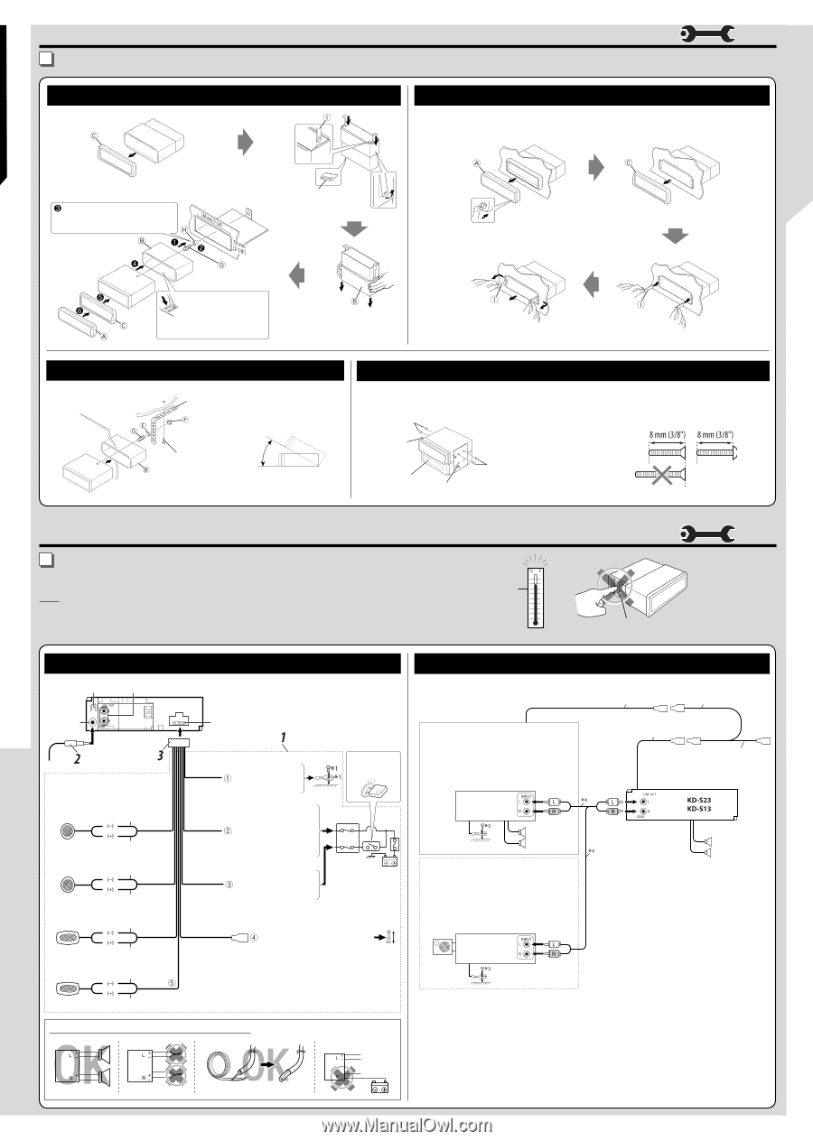
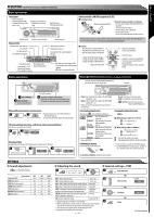
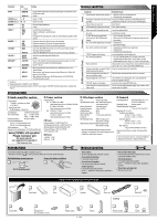
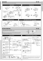
INSTALLATION / CONNECTION INSTALLATION If you are not sure how to install this unit correctly, consult your JVC car audio dealer. In dash-mounting Removing the unit Before removing the unit, release the rear section. Do the required electrical connections. When you stand the unit, be careful not to damage the fuse on the rear. Bend the appropriate tabs to hold the sleeve firmly in place. Dashboard When using the optional stay Fire wall Stay (option) Screw (option) Install the unit at an angle of less than 30˚. When installing the unit without using the sleeve In a Toyota car for example, first remove the car radio and install the unit in its place. Flat type screws -M5 × 8 mm (M5 × 3/8")* * Not supplied for this unit. Bracket* Pocket Bracket* Flat type screws -M5 × 8 mm (M5 × 3/8")* ELECTRICAL CONNECTIONS Make sure to disconnect the battery's negative terminal. • Be sure to ground this unit to the car's chassis again after installation. Note: It is recommended to connect to the speakers with maximum power of more than 45 W (both at the rear and at the front, with an impedance of 4 Ω to 8 Ω). If the maximum power is less than 45 W, change "AMP GAIN" setting to prevent the speakers from being damaged (see "General settings-PSM"). Rear ground terminal Line out Typical connections Antenna terminal 15 A fuse Connect only the front speakers if your speaker system is two-speaker system. White with black stripe Front speaker (left) White Gray with black stripe Front speaker (right) Gray Green with black stripe Rear speaker (left) Green Purple with black stripe Black To metallic body or chassis of the car Ignition switch Yellow *2 Red To a live terminal in the fuse block connecting to the car battery (bypassing the ignition switch) (constant 12 V) To an accessory terminal in the fuse block Fuse block Blue with white stripe To the remote lead of other equipment or automatic antenna if any (200 mA max.) High Heat sink Connecting the external amplifier or subwoofer Set "L/O MODE" to "REAR" (See "General settings-PSM.") You can connect a power amplifier for rear speakers. Remote lead Y-connector *1 Remote lead (blue with white stripe) To the remote lead of other equipment or automatic antenna if any JVC Amplifier Rear speakers Set "L/O MODE" to "WOOFER" (See "General settings-PSM.") You can also connect a subwoofer to the REAR LINE OUT terminals. Front speakers JVC Amplifier Subwoofer Rear speaker (right) Purple PRECAUTIONS on power supply and speaker connections *1 Not supplied for this unit. *2 Before checking the operation of this unit prior to installation, this lead must be connected, otherwise power cannot be turned on. *3 Firmly attach the ground wire to the metallic body or to the chassis of the car-to the place uncoated with paint (if coated with paint, remove the paint before attaching the wire). Failure to do so may cause damage to the unit. *4 Signal cord (not supplied for this unit) 4 - EN
-
 1
1 -
 2
2 -
 3
3 -
 4
4
 |
 |