JVC KY-F75U KY-F75U 52 page instruction manual (3MB)
JVC KY-F75U - 3-ccd Sxga Digital Imaging Camera Manual
 |
View all JVC KY-F75U manuals
Add to My Manuals
Save this manual to your list of manuals |
JVC KY-F75U manual content summary:
- JVC KY-F75U | KY-F75U 52 page instruction manual (3MB) - Page 1
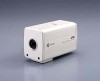
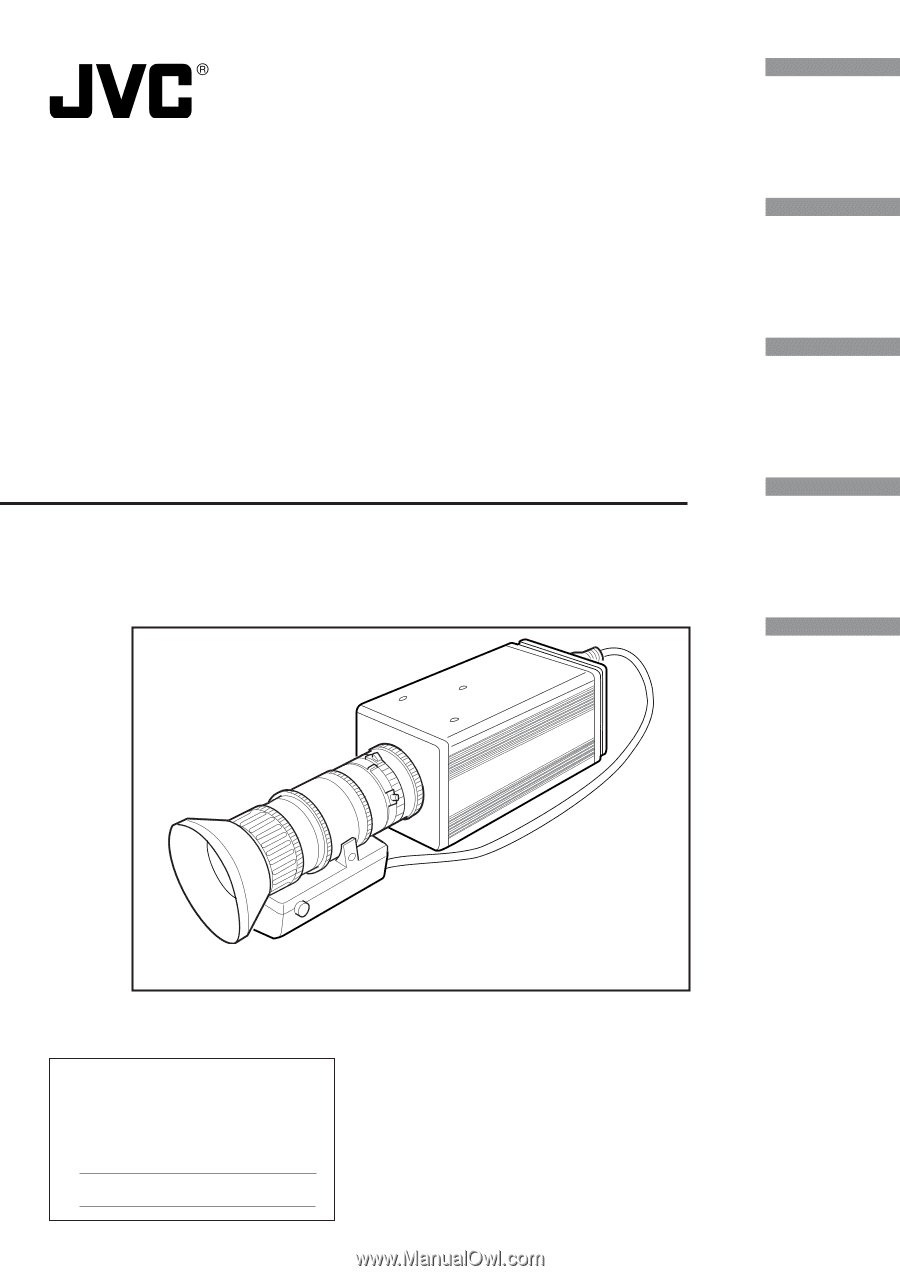
Introduction Preparations 3CCD Digital Camera 3CCD Digitale Kamera 3CCD Caméra numérique KY-F75 INSTRUCTIONS BEDIENUNGSANLEITUNG MANUEL D'INSTRUCTIONS Recording Settings Others Illustration with optional lens attachment. For Customer Use: Enter below the Serial No. which is located on the - JVC KY-F75U | KY-F75U 52 page instruction manual (3MB) - Page 2
to your home, consult your dealer or local power company. For appliance designed to operate from battery power, refer to the operating instructions. 10. This appliance system is equipped with a 3-wire grounding type plug (a plug having a third (grounding) pin). This plug will only fit into - JVC KY-F75U | KY-F75U 52 page instruction manual (3MB) - Page 3
qualified service personnel under following conditions: a. When the power cord or plug is damaged or frayed. b. If liquid has been spilled into the appliance. c. If the appliance has been exposed to rain or water. d. If the appliance does not operate normally by following the operating instructions - JVC KY-F75U | KY-F75U 52 page instruction manual (3MB) - Page 4
750 EDIFICIO CAN CASTANYER 08190 SANT CUGAT DEL VALLES (BARCELONA) SPAIN TEL : (93)5653210 6. JVC BELGIUM S.A./N.V. RUE DE LA PETITE LLE 3, KLEINEILANDSTRAAT, BRUXELLES 1070 BRUSSEL, BELGIUM TEL : (02)529-4211 8. JVC SVENSKA AB VEDDESTAVAGEN 15, S-175 62 JARFALLA-STOCKHOLM, SWEDEN TEL : (08)7950400 - JVC KY-F75U | KY-F75U 52 page instruction manual (3MB) - Page 5
SAFETY PRECAUTIONS FOR USA AND CANADA This symbol indicates type B equipment classified in accordance with IEC Publication. 601-1 Safety of medical electrical equipment. For Sweden VARNING Explosionsfara vid felaktigt batteribyte. Använd samma batterityp eller en ekvivalent typ som rekommenderas - JVC KY-F75U | KY-F75U 52 page instruction manual (3MB) - Page 6
you for purchasing the JVC KY-F75 Digital Camera. These instructions are for KY-F75U. The instructions are given in three SHOCK, DO NOT REMOVE COVER (OR BACK). NO USER SERVICEABLE PARTS INSIDE. REFER SERVICING TO QUALIFIED SERVICE PERSONNEL. The lightning flash with arrowhead symbol, within an - JVC KY-F75U | KY-F75U 52 page instruction manual (3MB) - Page 7
SAFETY PRECAUTIONS This equipment is in conformity with the provisions and protection requirements of the corresponding European Directives. This equipment is designed for professional video appliances and can be used in the following environments. • residential area (in houses) or rural area • - JVC KY-F75U | KY-F75U 52 page instruction manual (3MB) - Page 8
setting the lens 15 Connecting the AC adapter 16 Mounting the camera 18 Fall prevention 19 3. Recording Opening and closing the KY-LINK] application software 21 Freezing the image 22 Capturing the still image on the computer (Capture 23 Characters and symbols used in this instruction - JVC KY-F75U | KY-F75U 52 page instruction manual (3MB) - Page 9
-ROM for details. Wire clamp (5 pcs.) For clamping cables on the rear. INSTRUCTIONS MEMO To allow control of the camera and allow the camera image to be shown, the IEEE1394 host adapter and the exclusive application software [KY-LINK] must be installed in the computer. Use the separately sold KA - JVC KY-F75U | KY-F75U 52 page instruction manual (3MB) - Page 10
. Ⅵ Cleaning When clean the equipment please use dry cleaning cloth or wet cleaning cloth with small amount of alcohol. Do not spill any liquid into KY-F75. E6 - JVC KY-F75U | KY-F75U 52 page instruction manual (3MB) - Page 11
the bracket can also be mounted on the top of the camera. Mounting the camera ( ੬ page E18) » Locking screws for the camera mounting bracket (M2.6 × 6mm, 3 units) ¿ Screw holes for mounting the camera (1/4-inch) Used when mounting the camera to a fixer or rotating platform. CAUTION Always use the - JVC KY-F75U | KY-F75U 52 page instruction manual (3MB) - Page 12
REMOTE LENS IEEE1394 DC IN POWER SEE INSTRUCTION MANUAL ᕥ ᕩ ᕥ [IEEE1394] digital output connector Digital output connector for video signal. Used when power is supplied to the camera. ᕩ [DC IN] connector (Mini DIN 8-pin, female) Power (DC 12V) for the camera is supplied through this inlet. For - JVC KY-F75U | KY-F75U 52 page instruction manual (3MB) - Page 13
- TRG IN L active NC FLASH OUT L active - NC NC GND 12V output (only when power is supplied from AC adapter) NC CAUTION • Consult your JVC dealer concerning the re- mote terminal connection. • Remote cable must use shielded cable. Outer shield of remote cable must to connect 10-pin connector outer - JVC KY-F75U | KY-F75U 52 page instruction manual (3MB) - Page 14
IEEE1394 cable CD-ROM supplied with KY-F75: Exclusive application software [KY-LINK] and drivers for KAFW4IU IEEE1394 Host Adapter Lens Flash the camera to the IEEE1394 cable. The power to the KY-F75 can be supplied through the IEEE1394 connector of the computer. Caution When the KY-F75 is - JVC KY-F75U | KY-F75U 52 page instruction manual (3MB) - Page 15
DC IN] CD-ROM supplied with KY-F75: Exclusive application software [KY-LINK] and drivers for KAFW4IU Control cable Flash Compatible disconnect the IEEE1394 cable, while the application software [KY-LINK] is running. ● When connecting 2 or more cameras to one computer, multiple images can- - JVC KY-F75U | KY-F75U 52 page instruction manual (3MB) - Page 16
IEEE1394 PCI host adapter card: JVC: KA-FW4IU ● The driver is found on the CD-ROM supplied with the KY-F75. Ⅵ To display the camera image and control the camera, the exclusive [KY-LINK] application software must be installed in the computer. The [KY-LINK] application software is found in the CD-ROM - JVC KY-F75U | KY-F75U 52 page instruction manual (3MB) - Page 17
1. Install the IEEE1394 host adapter card KA-FW4IU and the drivers before installation of the [KY-LINK] application software. ● For how to install the KA-FW4IU, refer to the instructions for the KA-FW4IU. Also, for installation of the driver, see the Readme file on the CD-ROM supplied with the - JVC KY-F75U | KY-F75U 52 page instruction manual (3MB) - Page 18
card with the IEEE1394 cable. KY-F75 rear panel REMOTE LENS IEEE1394 DC IN POWER SEE INSTRUCTION MANUAL IEEE1394 cable IEEE1394 Host Adapter , see the instructions for the IEEE1394 host adapter card. • When the motorized lens is used, make sure to supply the power from the camera's [DC IN - JVC KY-F75U | KY-F75U 52 page instruction manual (3MB) - Page 19
. For further details, see the instruction manual for the lens and the lens remote control. Camera head Thread section Mount clamp ring Lens the remote control. 5. Make settings on the setting screen of the application software [KY-LINK] in accordance with the used lens. Ⅵ Iris mode settings on the - JVC KY-F75U | KY-F75U 52 page instruction manual (3MB) - Page 20
used to connect the KY-F75's [DC IN] connector and the [TO CAMERA] connector on the AC adapter (AA-P700). AA-P700 AC 100V AC adapter (separately sold) DC 12V=OUTPUT VIDEO OUTPUT S(Y/C) OUTPUT TO CAMERA REMOTE LENS IEEE1394 EITHER OUTPUT MAX 1.25A SEE INSTRUCTION MANUAL DC IN POWER White - JVC KY-F75U | KY-F75U 52 page instruction manual (3MB) - Page 21
or more after the power switch on the AA-P700 is set to ON before invoking the [KY-LINK] application software. Ⅵ Turning the power OFF Wait for 5 seconds or more after the [KY-LINK] application software is closed before setting the power switch on the AA-P700 to OFF. CAUTION • After the power - JVC KY-F75U | KY-F75U 52 page instruction manual (3MB) - Page 22
, use the rotation prevention hole to prevent the unit from falling and securely mount the unit. < Changing the camera mounting bracket position > When shipped, the camera mounting bracket is mounted on the bottom of the unit. To mount it on the top of the unit, simply remove the 3 locking screws - JVC KY-F75U | KY-F75U 52 page instruction manual (3MB) - Page 23
connect the unit to a strong surface with a wire chain, etc. When connecting such chain, use the bracket locking screw hole on the side which the camera mounting bracket is not mounted. (M2.6 × 6mm) Take special caution to the length of the optional wire as well. • For the fall-preventive wire, use - JVC KY-F75U | KY-F75U 52 page instruction manual (3MB) - Page 24
3. Recording How to record Operations for the various settings of the KY-F75 and camera recording are performed using the [KY-LINK] application software. Digital images are transferred from the camera to the computer at a rate of 7.5 frames per second. When a footswitch or other external trigger - JVC KY-F75U | KY-F75U 52 page instruction manual (3MB) - Page 25
the [OK] button. ● The selected camera image is displayed. (Live image is shown at a rate of 7.5 frames per second.) MEMO For details on the operation of the [KY-LINK] application software, see the Help file for the [KY-LINK] application software. This manual only explains the broad outlines of the - JVC KY-F75U | KY-F75U 52 page instruction manual (3MB) - Page 26
, and ALC is/are used MEMO The freeze function of the KY-F75 is accomplished in the memory of the computer by stopping the output of the camera image. Accordingly, if the trigger is input to the camera while the live-window is not shown, an image will not appear even if the live - JVC KY-F75U | KY-F75U 52 page instruction manual (3MB) - Page 27
button, and then give the image a name and save the file. Closing the KY-LINK application Ⅵ Select [Exit] from the File menu. Caution • Wait for 5 seconds or more after closing the [KY-LINK] before turning the KY-F75 OFF. • Do not turn OFF the power to the camera while the [KY-LINK] is running. E23 - JVC KY-F75U | KY-F75U 52 page instruction manual (3MB) - Page 28
set in the camera the next time the system is started up. Procedure 1. Turn ON the KY-F75 and wait for 5 seconds or more. 2. Start up the [KY-LINK] application software. ( ੬ page E21) 3. Open the Settings screen. ● The Settings screen is displayed by clicking the [Show Control Window] button in - JVC KY-F75U | KY-F75U 52 page instruction manual (3MB) - Page 29
5. Set the items on the Settings screen. For settings on the various setting screens, see pages E26 to E42. 6. Completing the settings on the Settings screen. Click the [X] (Close) button. File [Load], [Save] [Close] button --- Saving the setting values on the computer --- ● Save the setting - JVC KY-F75U | KY-F75U 52 page instruction manual (3MB) - Page 30
4. Settings (continued) Exposure settings screen This screen is used to make settings related to the image level, such as Iris, Shutter, and Sensi- tivity. Shutter settings Iris settings Restart button Valid when the shutter speed is 2 sec or slower in the V. SCAN mode. ALC max settings Sets - JVC KY-F75U | KY-F75U 52 page instruction manual (3MB) - Page 31
to set the iris level when the Iris mode is set to "MANUAL". When an motorized lens is used, this sets the iris level when manual iris control on the camera is used. Increasing the value: Open the iris Decreasing the value: Closes the iris Used to adjust the video level when auto - JVC KY-F75U | KY-F75U 52 page instruction manual (3MB) - Page 32
use a shutter speed of 2 sec or longer, use with the following settings selected: (However, 1.000 sec or longer at the time of V.SCAN.) Iris mode : MANUAL Gain : STEP or V.GAIN • There may be shortage of light when the shutter speed is increased. In this case, adjust the iris or sensitivity - JVC KY-F75U | KY-F75U 52 page instruction manual (3MB) - Page 33
[ ] indicates the factory setting Item Set Value Gain [STEP] ALC V.GAIN Level When "STEP" is selected Level When "V. GAIN" is selected ALC max EEI limit [0dB] +6dB +12dB [0.0dB] +0.2dB +0.4dB • • +12dB [+12dB] +6dB [1/7.5s] 1s Contents Used to switch the sensitivity mode. STEP: The - JVC KY-F75U | KY-F75U 52 page instruction manual (3MB) - Page 34
and WHITE BALANCE are set. * Regard the values as reference values. COLOR TEMP WHITE BALANCE 2000K 3200K COLOR TEMP 5600K 5200K 15000K 3200K PRESET AUTO MANUAL 5600K PRESET AUTO - JVC KY-F75U | KY-F75U 52 page instruction manual (3MB) - Page 35
value: Red tint of screen becomes weaker The blue color in the white balance can be adjusted when [White bal.] is set to "AUTO" or "MANUAL". Increasing the value: Blue tint of screen becomes stronger Decreasing the value: Blue tint of screen becomes weaker Click this button to perform auto white - JVC KY-F75U | KY-F75U 52 page instruction manual (3MB) - Page 36
4. Settings (continued) White balance settings screen (continued) [ ] indicates the factory setting Item Set Value Shading [OFF] ON Contents Used to set whether to perform white shading adjustment. OFF: no white shading adjustment ON: the white shading can be adjusted. Level (R) Level (G) - JVC KY-F75U | KY-F75U 52 page instruction manual (3MB) - Page 37
bal item to AUTO1 or AUTO2. 5. Click the Auto white button. ● The KY-F75 automatically adjusts the white balance. * When a slow the shutter speed has launch the auto white balance function, or set the item [White bal] to "MANUAL" or "PRESET". • Pressing the [Auto White] button in the FREEZE condition - JVC KY-F75U | KY-F75U 52 page instruction manual (3MB) - Page 38
can occur due to the combination of lenses and the optical system that 3CCD cameras are equipped with. If this happens, perform adjustment as described in the following. Waveform window button KY-LINK screen tool bar Video signal level Setting screen V button R button G button B button 1. Shoot - JVC KY-F75U | KY-F75U 52 page instruction manual (3MB) - Page 39
Process settings screen This screen is used to make settings related to the picture quality, such as detail compensation, gamma, and white spot compensation. Detail settings Gamma settings Flare setting ABL setting Master black setting DSP bypass setting Nega setting Noise sup. setting [ ] - JVC KY-F75U | KY-F75U 52 page instruction manual (3MB) - Page 40
However, the gradation of bright areas becomes poorer. Selects whether the camera image should be negative signal. ON: Conversion to negative signal OFF: Conversion to negative signal is not made. Selects whether DSP (Digital Signal Processing) should be bypassed. NORMAL: Not bypassed. BYPASS: - JVC KY-F75U | KY-F75U 52 page instruction manual (3MB) - Page 41
[ ] indicates the factory setting Item Master black Set Value - 99 : [0] • 99 Flare [ON] OFF Level (R) When "ON" is selected. Level (B) When "ON" is selected. ABL - 32 - 31 • [0] • 31 - 32 - 31 • [0] • 31 [ON] OFF Level When "ON" is selected. Pixel comp. - 32 - 31 • [0] • 31 [OFF] ON Pixel - JVC KY-F75U | KY-F75U 52 page instruction manual (3MB) - Page 42
temperatures. To moderate this phenomenon, this camera is provided with a white spot compensation will be closed automatically.) 3. Display the [KY-LINK] application software's Process setting screen. 4. Set the Pixel spot detection, the image in the live window will become a still picture, but this - JVC KY-F75U | KY-F75U 52 page instruction manual (3MB) - Page 43
Color matrix settings screen Used to set the color tone of the camera image. Selects the color matrix. Slider bar: Valid when ON is selected as the Color matrix. Make adjustments by dragging the slider bars with the mouse. Fine adjustment can be made with the keyboard's [ǟ] and [Ǟ] keys. E39 - JVC KY-F75U | KY-F75U 52 page instruction manual (3MB) - Page 44
4. Settings (continued) Color matrix settings screen (continued) [ ] indicates the factory setting Item Color matrix Set Value ON [OFF] R - G [0] 1 R - G • • G - R (+) • 31 G - R (-) Contents Used to set whether or not colour matrix values remain standard. ON: the colour matrix becomes - JVC KY-F75U | KY-F75U 52 page instruction manual (3MB) - Page 45
connected to the [LENS] connector, the setting automatically becomes "MANUAL". Used to set the iris level when the Iris mode is set to "MANUAL". When an motorized lens is used, this sets the iris level when manual iris control on the camera is used. Increasing the value: Opens the iris Decreasing - JVC KY-F75U | KY-F75U 52 page instruction manual (3MB) - Page 46
, when KY-LINK is started up, it recalls and sets the camera to the values valid when it was closed down the previous time. Consequently, the settings saved in the camera with the Save button are made invalid. Item Freeze cancel Test pattern Pattern level When "BAR" is selected. Set Value [MANUAL - JVC KY-F75U | KY-F75U 52 page instruction manual (3MB) - Page 47
" ( ੬ page E28, Shutter item) ● In response to the trigger input, the KY-F75 outputs a flash signal for the CCD accumulation period of the next frame. ● The 1/7.5 s or faster. ● When the FREEZE cancel mode is set to "MANUAL", FLASH will not be output in response to the trigger input for FREEZE - JVC KY-F75U | KY-F75U 52 page instruction manual (3MB) - Page 48
5. Others (continued) Synchronizing flash and trigger (continued) Ⅵ When the shutter mode is "RANDOM" • CCD accumulation is performed in sync with the trigger input, and this period is output as the FLASH signal. • At the same shutter speeds the delay from the trigger input to the FLASH output is - JVC KY-F75U | KY-F75U 52 page instruction manual (3MB) - Page 49
in the range of 2 graduations of the aperture under dark lighting and 8 graduations under bright lighting. When the IRIS mode is set to manual, the sensitivity and electronic shutter change continuously while the iris setting stays fixed. ( ੬ page E27 Iris mode) This feature holds the advantage of - JVC KY-F75U | KY-F75U 52 page instruction manual (3MB) - Page 50
5906.836s C mount IEEE1394 - 1995 (IIDC 1394-based Digital Camera Specification Ver. 1.30 standard) 7.5 frames/s 10 bits MB or more empty hard disk space (space for application software install) G OS: Windows 98SE/Me/2000pro/XP G Video circuit: Circuit capable of full-color dis- Service parts) E46 - JVC KY-F75U | KY-F75U 52 page instruction manual (3MB) - Page 51
External dimensions (unit: mm) 70 1 C-Mount 150 142.5 C-MOUNT DIGITAL CAMERA KY-F75U 88 80 41.5 14 1/4-inch screw Design and specifications are subject to change without notice. E47 - JVC KY-F75U | KY-F75U 52 page instruction manual (3MB) - Page 52
VICTOR COMPANY OF JAPAN, LIMITED is a registered trademark owned by VICTOR COMPANY OF JAPAN, LTD. is a registered trademark in Japan, the U.S.A., the U.K. and many other countries. © 2002 VICTOR COMPANY OF JAPAN, LIMITED Printed in Japan LWT0059-001A KY-F75 3CCD Digital Camera
-
 1
1 -
 2
2 -
 3
3 -
 4
4 -
 5
5 -
 6
6 -
 7
7 -
8
-
9
-
10
-
11
-
12
-
13
-
14
-
15
-
16
-
17
-
18
-
19
-
20
-
21
-
22
-
23
-
24
-
25
-
26
-
27
-
28
-
29
-
30
-
31
-
32
-
33
-
34
-
35
-
36
-
37
-
38
-
39
-
40
-
41
-
42
-
43
-
44
-
45
-
46
-
47
-
48
-
49
-
50
-
51
-
52
 |
 |
INSTRUCTIONS
BEDIENUNGSANLEITUNG
MANUEL D’INSTRUCTIONS
3CCD Digital Camera
3CCD Digitale Kamera
3CCD Caméra numérique
KY-F75
Illustration with optional lens attachment.
This instruction book is made from 100%
recycled paper.
LWT0059-001A
For Customer Use:
Enter below the Serial No. which is
located on the unit. Retain this
information for future reference.
Model No.
KY-F75
Serial No.
Introduction
Preparations
Recording
Settings
Others