JVC TH-A25 Instruction Manual - Page 13
DBS Tuner, Center unit, MD Recorder, Cassette Deck, Now - manual
 |
UPC - 046838260377
View all JVC TH-A25 manuals
Add to My Manuals
Save this manual to your list of manuals |
Page 13 highlights
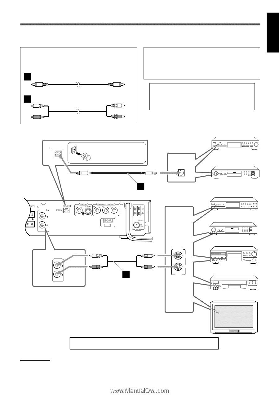
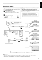
English Audio component connection Connect other components to the center unit with the audio cord. Use the cord supplied with the other component or purchase one at an electric appliance store. A Optical digital cord (not supplied) B Audio cord (not supplied) Illustrations of the input/output terminals below are typical examples. When you connect other components, refer also to their manuals since the terminal name actually printed on the rear vary among the components. If you connect a sound-enhancing device such as a graphic equalizer between the source component and the center unit, the sound output through this system may be distorted. DIGITAL IN OPTICAL Before connecting an optical digital cord, unplug the protective plug. A Center unit AUDIO IN L R REAR AUX 110- 220- 127V 240V AUDIO IN B AUX DIGITAL OPTICAL OUT AUDIO LEFT RIGHT OUT DBS Tuner MD Recorder DBS Tuner MD Recorder Cassette Deck VCR TV Now, you can plug the power cord of the center unit into the AC outlet. Notes: • Keep the power cord away from the connecting cords and the antenna. The power cord may cause noise or screen interference. • Connecting to a TV through a VCR, or to a TV with a built-in VCR, may cause distortion of picture. • If the AC outlets do not match the AC plug, use the supplied AC plug adapter (not supplied for Hong Kong). 9
-
 1
1 -
2
-
3
-
4
-
5
-
6
-
7
-
 8
8 -
 9
9 -
 10
10 -
 11
11 -
 12
12 -
 13
13 -
 14
14 -
 15
15 -
 16
16 -
 17
17 -
 18
18 -
19
-
20
-
21
-
22
-
23
-
24
-
25
-
26
-
27
-
28
-
29
-
30
-
31
-
32
-
33
-
34
-
35
-
36
-
37
-
38
-
39
-
40
-
41
-
42
-
43
-
44
-
45
-
46
-
47
-
48
-
49
-
50
-
51
-
52
-
53
-
54
-
55
-
56
-
57
-
58
-
59
-
60
-
61
-
62
-
63
-
64
-
65
-
66
-
67
-
68
-
69
-
70
-
71
-
72
-
73
-
74
-
75
-
76
-
77
-
78
-
79
-
80
-
81
-
82
-
83
-
84
-
85
-
86
-
87
-
88
-
89
-
90
-
91
-
92
-
93
-
94
-
95
-
96
-
97
-
98
-
99
-
100
-
101
-
102
-
103
-
104
-
105
-
106
-
107
-
108
-
109
-
110
-
111
-
112
-
113
-
114
-
115
-
116
-
117
-
118
-
119
-
120
-
121
-
122
-
123
-
124
-
125
-
126
-
127
-
128
-
129
-
130
-
131
-
132
-
133
-
134
-
135
-
136
-
137
-
138
-
139
-
140
-
141
-
142
-
143
-
144
 |
 |