JVC TH-A25 Instruction Manual - Page 57
AM antenna connection, Center unit
 |
UPC - 046838260377
View all JVC TH-A25 manuals
Add to My Manuals
Save this manual to your list of manuals |
Page 57 highlights
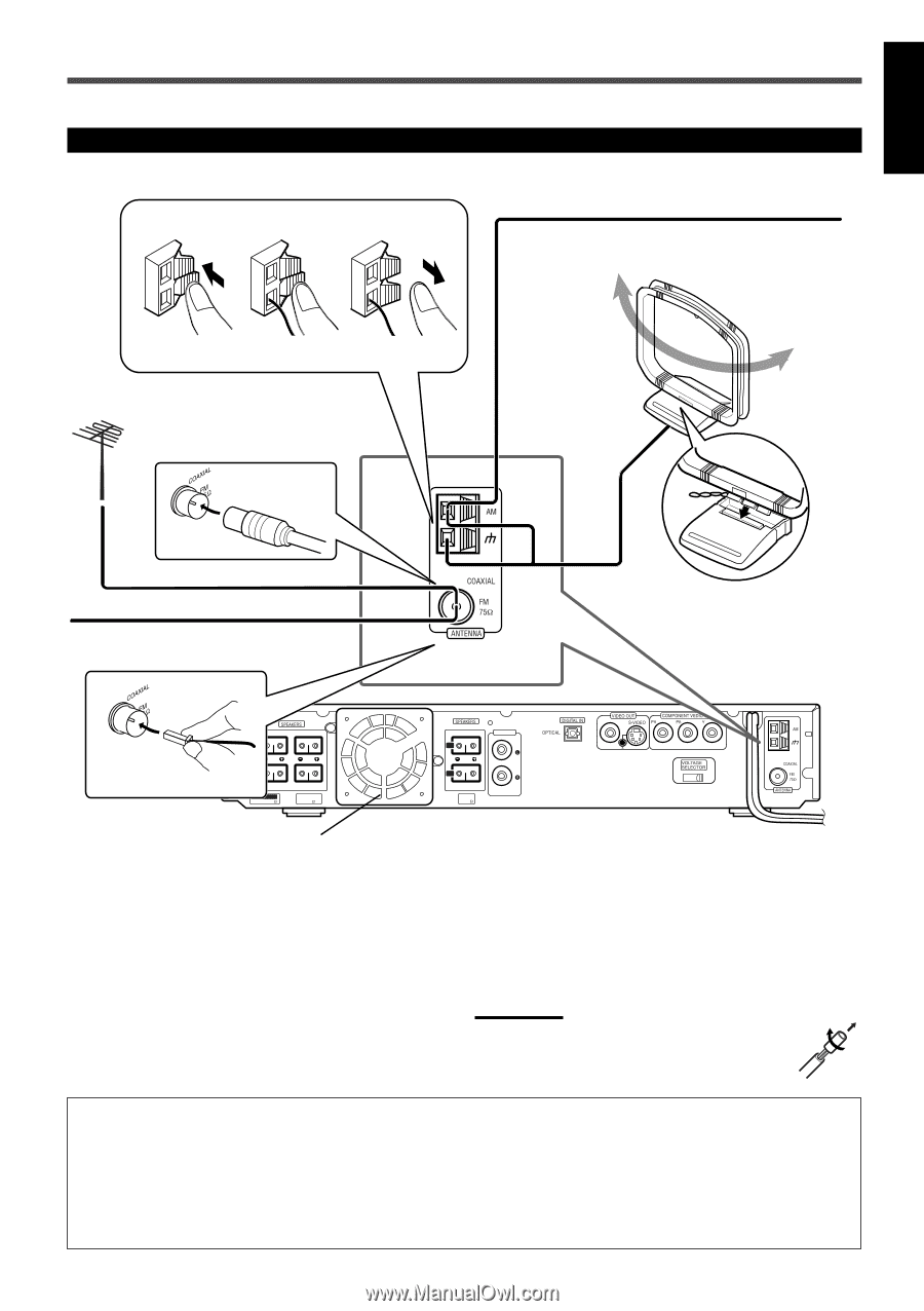
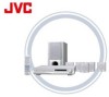
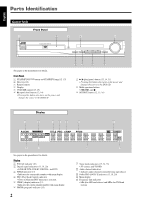
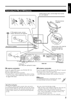
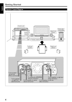
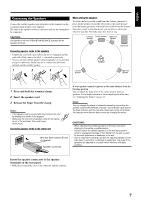
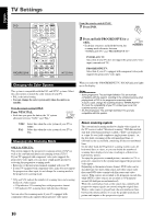
English Connecting the FM and AM Antennas 1 2 3 If AM reception is poor, connect single vinyl-covered wire (not supplied). AM Loop antenna (supplied) If FM reception is poor, connect outdoor FM antenna (not supplied). FM antenna (supplied) Snap the tabs on the loop into the slots of the base to assemble the AM Loop antenna. CENTER L R FRONT IMPEDANCE WOOFER:MIN 3 WOOFER FRONT/CENTER MIN 6 AUDIO IN L R REAR REAR MIN 6 AUX Cooling fan (See "About the cooling fan" below.) Center unit 110- 220- 127V 240V FM antenna connection Connect the supplied FM antenna to the COAXIAL FM 75 Ω terminal as temporary measure. Extend the supplied FM antenna horizontally. • If reception is poor, connect an outdoor antenna. Before attaching a 75 Ω coaxial cable (with a standard type connector), disconnect the supplied FM antenna. AM antenna connection Connect the supplied AM Loop antenna to the AM and H terminals. Turn the loop until you have the best reception. • If reception is poor, connect an outdoor single vinyl-covered wire to the AM terminal. (Keep the AM Loop antenna connected.) Notes: If the AM Loop antenna wire is covered with vinyl, remove the vinyl by twisting it as shown in the diagram. About the cooling fan A cooling fan is mounted on the rear panel of the center unit to prevent abnormal temperature inside the center unit, thus assuring normal operation of the unit. The cooling fan automatically starts rotating to intake external cool air when the internal temperature goes up. For safety, observe the following carefully. • Make sure there is good ventilation around the center unit. Poor ventilation could overheat and damage the center unit. • DO NOT block the cooling fan and the ventilation openings or holes. (If they are blocked by a newspaper or cloth, etc., the heat may not be able to get out.) • DO NOT touch the speaker cords to the cooling fan. 5
-
 1
1 -
2
-
3
-
4
-
5
-
6
-
7
-
8
-
9
-
10
-
11
-
12
-
13
-
14
-
15
-
16
-
17
-
18
-
19
-
20
-
21
-
22
-
23
-
24
-
25
-
26
-
27
-
28
-
29
-
30
-
31
-
32
-
33
-
34
-
35
-
36
-
37
-
38
-
39
-
40
-
41
-
42
-
43
-
44
-
45
-
46
-
47
-
48
-
49
-
50
-
51
-
 52
52 -
 53
53 -
 54
54 -
 55
55 -
 56
56 -
 57
57 -
 58
58 -
 59
59 -
 60
60 -
 61
61 -
 62
62 -
63
-
64
-
65
-
66
-
67
-
68
-
69
-
70
-
71
-
72
-
73
-
74
-
75
-
76
-
77
-
78
-
79
-
80
-
81
-
82
-
83
-
84
-
85
-
86
-
87
-
88
-
89
-
90
-
91
-
92
-
93
-
94
-
95
-
96
-
97
-
98
-
99
-
100
-
101
-
102
-
103
-
104
-
105
-
106
-
107
-
108
-
109
-
110
-
111
-
112
-
113
-
114
-
115
-
116
-
117
-
118
-
119
-
120
-
121
-
122
-
123
-
124
-
125
-
126
-
127
-
128
-
129
-
130
-
131
-
132
-
133
-
134
-
135
-
136
-
137
-
138
-
139
-
140
-
141
-
142
-
143
-
144
 |
 |