JVC TK-C1530U Instructions
JVC TK-C1530U - CCTV Camera Manual
 |
UPC - 046838027925
View all JVC TK-C1530U manuals
Add to My Manuals
Save this manual to your list of manuals |
JVC TK-C1530U manual content summary:
- JVC TK-C1530U | Instructions - Page 1
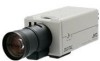
COLOR VIDEO CAMERA TK-C1530U/E TK-C1531EG INSTRUCTIONS For Customer Use: Enter below the Serial No. which is located on the body. Retain this information for future reference. Model No. TK-C1530U/E,TK-C1531EG Serial No. LST0459-001C - JVC TK-C1530U | Instructions - Page 2
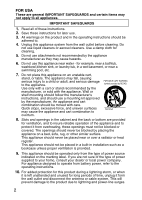
power supplied to your home, consult your dealer or local power company. For appliance designed to operate from battery power, refer to the operating instructions. 10. For added protection for this product during a lightning storm, or when it is left unattended and unused for long periods of time - JVC TK-C1530U | Instructions - Page 3
service personnel under the following conditions: a. When the power cord or plug is damaged or frayed. b. If liquid has been spilled into the appliance. c. If the appliance has been exposed to rain or water. d. If the appliance does not operate normally by following the operating instructions - JVC TK-C1530U | Instructions - Page 4
. The exclamation point within an equilateral triangle is intended to alert theuser to the presence of important operating and maintenance (servicing) instructions in the literature accompanying the appliance. WARNING: TO REDUCE THE RISK OF FIRE OR ELECTRIC SHOCK, DO NOT EXPOSE THIS APPLIANCE - JVC TK-C1530U | Instructions - Page 5
, if not installed and used in accordance with the instructions, may cause harmful interference to radio communications. However, there radio/TV technician for help. CAUTION CHANGES OR MODIFICATIONS NOT APPROVED BY JVC COULD VOID USER'S AUTHORITY TO OPERATE THE EQUIPMENT. THIS DEVICE COMPLIES WITH - JVC TK-C1530U | Instructions - Page 6
municipal office, your household waste disposal service or the shop where you purchased of this product, please visit our web page www.jvc-europe.com to obtain information about the take-back of to design modifications, data given in this instruction book are subject to possible change without prior - JVC TK-C1530U | Instructions - Page 7
inside. Refer servicing to qualified service personnel. Dear Customer, This apparatus is in conformance with the valid European directives and standards regarding electromagnetic compatibility and electrical safety. European representative of Victor Company of Japan Limited.is: JVC Technology Centre - JVC TK-C1530U | Instructions - Page 8
this product. (These instructions are for TK-C1530U/E and TK-C1531EG.) Before beginning to operate this unit, please read the instruction manual carefully in order to make sure that the best possible performance is obtained. Features Ⅵ Realizing a High Picture Quality This camera realizes 540 TV - JVC TK-C1530U | Instructions - Page 9
ADJUSTMENT screen 49 PRIVATE MASK screen 50 COMMUNICATION screen 51 MAINTENANCE screen 52 FACTORY SETTING screen 53 Detailed setting Camera title setting 54 Manual adjustment of white balance 56 Output of B&W/Color switching signal 58 Control by B&W/Color switching signal from external 60 - JVC TK-C1530U | Instructions - Page 10
sure to use a housing or the like. ⅷ Do not install or use the camera in the following places. ● In a place exposed to rain or moisture. ● In color. Maintenance ⅷ Turn off the power before performing maintenance. ⅷ Clean the camera with a soft cloth. Wiping it with thinner or benzene may melt the - JVC TK-C1530U | Instructions - Page 11
ⅷ When a high brightness object is shot, sometimes undulations can be observed on the vertical lines of the object. However, this phenomenon is peculiar to the camera and is not a malfunction. ⅷ Caution for operating the VIDEO IRIS lens If the LEVEL dial of the VIDEO IRIS lens is set to a low level - JVC TK-C1530U | Instructions - Page 12
is required, loosen the back focus fastening screw J by turning it anti-clockwise. After the adjustment, tighten the fastening screw by turning it clockwise. This camera is factory-adjusted to a suitable position with CS-mount lens. (A Pg. 28) B Lens Mount To attach the lens. This is suitable for CS - JVC TK-C1530U | Instructions - Page 13
Note: ● Do not use a screw that is longer than the specified length. It may damage the internal parts. I Camera-mounting bracket The bracket has been attached on the bottom of the camera before shipment. It can also be attached on the top according to the circumstance. (A Pg. 26) J [BF LOCK] Back - JVC TK-C1530U | Instructions - Page 14
CLASS 2 ONLY(U TYPE) ISOLATED POWER ONLY(E TYPE) SEE INSTRUCTION MANUAL POWER + ô DC12V d 1 2 AC24V H INT LL RX TERM-OFF ON MENU SET VIDEO OUT SELECTOR S R Q P O N Ⅵ TK-C1531EG T L M SEE INSTRUCTION MANUAL POWER INT LL RX TERM-OFF ON MENU SET VIDEO OUT SELECTOR S R Q P O N 14 - JVC TK-C1530U | Instructions - Page 15
K [AC24V,DC12V] Power input terminal To connect to AC 24 V or DC 12 V power supply. (A Pg. 22) L [TX+ A ,TX- B ,RX+ C ,RX- D ] Control signal connection terminal Terminal for inputting or outputting signals with electrical characteristics conforming to the EIATIA RS-422A or RS-485 standard. M [AUX, - JVC TK-C1530U | Instructions - Page 16
synchronization to the power frequency. (Default setting: INT) R [POWER] Power indicator lamp This lamp lights up when power is supplied to the camera. S Mounting Screw for Fall Prevention Wire Use this screw when mounting the fall prevention wire to this unit. (Fall prevention wire is not - JVC TK-C1530U | Instructions - Page 17
Switch) Power Cable TK-C1530U/E : AC24 V or DC12 V TK-C1531EG : AC220 V-240V Control Signal Cable Video Signal Cable Av Pk L H ALC LEVEL Camera 8 DIGITAL MACHINE used before connecting the cables. ● Read through the "Instruction Manual" of the devices to be used carefully before connecting. - JVC TK-C1530U | Instructions - Page 18
. Confirm switch settings on the monitor screen using the following methods. 1. Confirm that the image from the camera to be checked is displayed on the monitor. 2. Turn ON the power of the camera to be checked. The image is displayed on the monitor screen as shown below. (When MACHINE ID is - JVC TK-C1530U | Instructions - Page 19
the lens. Connecting the back panel (A Pg. 22) Connect the control signal cable, video signal coaxial cable and the like. Mounting the camera (A Pg. 25) Mount the camera to the mounting location. Adjusting the back focus (A Pg. 28) Adjust the back focus. Adjusting the lens (A Pg. 30) Adjust the lens - JVC TK-C1530U | Instructions - Page 20
Setup Mounting the lens 1 (a) F (b) 3 VIDEO DC 2 IRIS VIDEO DC COLOR VIDEO CAMERA LEVEL 13 24 4 20 4 pin plug 3 1 4 2 - JVC TK-C1530U | Instructions - Page 21
value that is shown in the table below. Note: ● Never use one that exceeds the dimension (a) as it will damage the inner part of the camera and will not allow normal installation. This will result in a malfunction. Lens C-mount lens CS-mount lens Flange back (b) 17.526 mm 12.5 mm Dimension - JVC TK-C1530U | Instructions - Page 22
supply (TK-C1530U/E) Connect to AC 220 V240 V power supply (TK-C1531EG) CLASS 2 ONLY(U TYPE) ISOLATED POWER ONLY(E TYPE) SEE INSTRUCTION MANUAL POWER connected to a GND terminal. Connect to the TO CAMERA terminal of RM-P2580E Connecting the power cable Ⅵ TK-C1530 (AC24 V or DC12 V) Connect the AC - JVC TK-C1530U | Instructions - Page 23
not connect an AC 24 V cable to a commercial power supply. The camera will be damaged. If the wrong cable is connected, the internal circuit may be damaged. Do not use the camera. Bring it to your nearest JVC dealer for inspection. Ⅵ TK-C1531EG (AC 220 V-240 V) Connect the power supply cable to the - JVC TK-C1530U | Instructions - Page 24
ms. The recognition of alarm signal may not be guaranteed if less than 200 ms. CLASS 2 ONLY(U TYPE) ISOLATED POWER ONLY(E TYPE) SEE INSTRUCTION MANUAL POWER + ô DC12V d 1 2 AC24V H INT LL RX TERM-OFF ON MENU SET VIDEO OUT SELECTOR IN Z GND Z Please use a shilded cable. Ⅵ Alarm output - JVC TK-C1530U | Instructions - Page 25
-mounting bracket fixing screws (x2: M2.6 x 6 mm) Rotation-preventive hole Camera-mounting bracket IRIS VIDEO DC COLOR VIDEO CAMERA LEVEL 7 mm or less Note: ● Use a camera-mounting screw with a length shorter than 7 mm from the camera-mounting face. Do not use a screw that is longer than the - JVC TK-C1530U | Instructions - Page 26
bracket is originally mounted at the bottom of the camera before shipment but it can also be mounted on top of the camera. 1 Camera-mounting bracket 2 Camera-mounting bracket fastening screws To mount the cameramounting bracket on top of the camera, use the screw holes on the back panel. 3 COLOR - JVC TK-C1530U | Instructions - Page 27
/tilt unit and the like, make sure to install it firmly using a rotation-preventive hole to prevent fall. ● To prevent fall, connect the camera to a section with sufficient strength (ceiling slab or channel) using a fall prevention wire. ● Pay attention to the length, strength, routing and material - JVC TK-C1530U | Instructions - Page 28
Setup Adjusting the back focus This camera is adjusted to a optimum wide range for CS-mount lens before shipment but readjustment is required when using zoom lens or C-mount lens or when - JVC TK-C1530U | Instructions - Page 29
focus fastening screw by turning it clockwise. With a zoom lens If the image is out of focus when zooming (telephoto - wide angle), adjust the camera as follows. 1. Loosen the back focus fastening screw by turning it anti-clockwise with a + screwdriver. 2. Shooting an object or a picture with fine - JVC TK-C1530U | Instructions - Page 30
combination. If the image is unnatural, adjust it. ● Also read the instruction manual of the lens. Ⅵ With a VIDEO automatic iris lens (Automatic iris control lens with built-in EE amplifier) Set the switch at the side of the camera to AVIDEOB and adjust the LEVEL dial on the lens. LEVEL adjustment - JVC TK-C1530U | Instructions - Page 31
Clockwise (Towards H) Memo: ● If the LEVEL sensitivity adjustment is turned excessively to L, the sensitivity increases because of the AGC function of the camera and the image looks grainy. ● Depending on the lens used, if the LEVEL dial is turned excessively to L, the hunting phenomenon (floppy - JVC TK-C1530U | Instructions - Page 32
object is changed, press the SET button for a while and adjust the white balance again. CLASS 2 ONLY(U TYPE) ISOLATED POWER ONLY(E TYPE) SEE INSTRUCTION MANUAL POWER + ô DC12V d 1 2 AC24V H INT LL RX TERM-OFF ON MENU SET VIDEO OUT SELECTOR 2 SET button 3 AWC OPERATION AWC OK Ⅵ Error - JVC TK-C1530U | Instructions - Page 33
1. Place a white object at the center of the screen, under the same lighting condition as the object to be shot and zoom in to fill the screen with white. 2. Press the SET button for approx. one second. Auto white balance adjustment begins. During operation, AAWC OPERATIONB is displayed on the - JVC TK-C1530U | Instructions - Page 34
Setting Menu basic operation CLASS 2 ONLY(U TYPE) ISOLATED POWER ONLY(E TYPE) SEE INSTRUCTION MANUAL POWER + ô DC12V d 1 2 AC24V H INT LL RX TERM-OFF ON MENU SET VIDEO OUT SELECTOR MENU button SET button and SELECTOR switch 1. Press the MENU button - JVC TK-C1530U | Instructions - Page 35
changed, a change mark (Z) is displayed. The change mark (Z) disappears when the changed setting is saved. Change mark (Z) TITLE/VIDEO SCENE Z CAMERA TITLE EDIT.. W. BALANCE ATW SHUTTER.. GAIN.. B&W/COLOR.. EZBLC MODE AREA1 IRIS MODE AUTO S.E.C. OFF RETURN Memo: ● To change the - JVC TK-C1530U | Instructions - Page 36
in scene files (A Pg. 64) CAMERA TITLE EDIT When AAWCB is selected AWC EXECUTE W.BALANCE SHUTTER GAIN B&W/COLORZ W.BALANCE ADJUST MODE MANUAL SPEED AUTO LIMIT AWC SET R GAIN B GAIN MODE MAX GAIN FIX GAIN ZTK-C1530U only COLOUR is displayed for TK-C1530E/TK-C1531EG BLC MODE IRIS MODE S.E.C. - JVC TK-C1530U | Instructions - Page 37
ID When AONB is selected MASK EDIT This will not be displayed when the menu is activated using RM-P2580E and external communication. Use the camera switch to set this item. CCD SPOT SCAN CANCEL EXECUTE CANCEL CLEAR(WITHOUT TITLE) CLEAR(ALL) - JVC TK-C1530U | Instructions - Page 38
sets the signal input or output of the AUX terminal. B&W OUT : A signal is output when the camera switches to B&W or Color mode. SCENE IN : Depending on the input signal of the AUX terminal, the camera can switch between scene files (A, B only). IR IN : Depending on the input signal of the AUX - JVC TK-C1530U | Instructions - Page 39
DE) This is the Auto-Tracking White Balance mode. (Automatic color temperature tracking.) The camera adjusts the white balance automatically according to the color temperature of the illumination. This mode supports an even wider range of color temperature than ATW. Use this mode when white balance - JVC TK-C1530U | Instructions - Page 40
becomes. [Setting:0 to 255] This item sets the electronic shutter. Select the mode of the electronic shutter. MANUAL: This operates in the shutter speed set in the MANUAL SPEED item. AUTO : This automatically switches the shutter speed according to brightness. The fastest value of a shutter - JVC TK-C1530U | Instructions - Page 41
SPEED Functions and settings (continued) This sets a shutter speed when MANUAL is set. TK-C1530U [Setting: NORMAL, 1/100, 1/250, 1/500, 1/1000, 1/2000, 1/4000, 1/10000] [Default setting: NORMAL] TK-C1530E/TK-C1531EG [Setting: NORMAL, 1/120, 1/250, 1/500, 1/1000, 1/2000, 1/4000, 1/10000] [Default - JVC TK-C1530U | Instructions - Page 42
Setting TITLE/VIDEO screen (continued) Item GAIN Functions and settings This item sets the gain. Memo: ● If the gain is increased, the screen appears grainy in a dark place. MODE Select the gain adjustment mode. Sensitivity increases electronically for an object with low illumination. AGC ( - JVC TK-C1530U | Instructions - Page 43
Item GAIN MAX GAIN FIX GAIN Functions and settings (continued) This item sets a maximum gain of the AGC (Automatic Gain Control). 0(OFF) : No AGC function. HIGH : Increase the gain up to a maximum of 26dB according to the illumination of an object. SUPER : Increase the gain up to a maximum of 32dB - JVC TK-C1530U | Instructions - Page 44
TK-C1530U and ACOLOURB is displayed for TK-C1530E/TK-C1531EG. From this point onwards, ACOLORB will be used for indication. Item B&W/COLOR (TK-C1530U) B&W/ COLOUR (TK-C1530E/ TK the camera permanently to Color mode. B&W : Sets the camera permanently to B&W mode. AUTO : The camera automatically - JVC TK-C1530U | Instructions - Page 45
and settings B&W/COLOR (continued) MODE [Default setting: COLOR] (continu ZDisplay for TK-C1530U. For TK-C1530E/ ed) TK-C1531EG, COLOUR is displayed. Memo: To ensure a successful B&W/Color switching ● If sensor (available separately) to the alarm terminal of this camera before switching. 45 - JVC TK-C1530U | Instructions - Page 46
to AAUTOB, this function sets the signal level of the object where the camera will switch to B&W mode. LOW : Switches to B&W mode when the object indicates high illumination. [Default setting: NORMAL] ZDisplay for TK-C1530U. For TK-C1530E/ TK-C1531EG, COLOUR is displayed. Memo: ● When MODE item of - JVC TK-C1530U | Instructions - Page 47
Item Functions and settings B&W/COLOR (continued) COLOR OVERLAY (TK-C1530U) COLOUR OVERLAY (TK-C1530E/ TK-C1531EG) This function gives a pseudo color to the image under natural lighting such as moonlight or low brightness light. Color reproducibility is poor under artificial - JVC TK-C1530U | Instructions - Page 48
. AUTO : Automatic iris is enabled. OPEN : Forces the automatic iris to open. [Default setting: AUTO] Memo: ● This setting does not function when a manual iris lens is used. S.E.C (Smart Edge Control) This item emphasizes images with very fine and detailed parts. This will increase the visual - JVC TK-C1530U | Instructions - Page 49
screen Item V.PHASE Functions and settings This adjusts the vertical synchronization to those of other cameras when a selector switch for the synchronizing system on the back of the camera is at ALLB. TK-C1530U This item can only operate in a region with a power frequency of 60 Hz. [Setting: -131 - JVC TK-C1530U | Instructions - Page 50
Setting PRIVATE MASK screen Item MASK No.1 MASK No.2 MASK No.3 MASK No.4 Functions and settings This function masks parts of an image in gray display such that the masked parts will not be shown on the screen. Select AONB and press the SET button. The MASK EDIT screen appears and mask settings - JVC TK-C1530U | Instructions - Page 51
. [Default setting: P TO P] MACHINE ID This is set when the STYLE item is set to AMULTIDROPB. This number identifies individual cameras in a group. This item does not operate properly if an ID number is repeated within a system. When used in combination with RM-P2580E, set the - JVC TK-C1530U | Instructions - Page 52
is 32. ● White spots may not be compensated due to its properties. ● As white spot compensation is interpolated from the surrounding pixels, the camera may not acquire accurate image information when the object has very fine pattern. ● The result of white spot compensation is maintained until the - JVC TK-C1530U | Instructions - Page 53
FACTORY SETTING screen The values set on the menu are returned to the default settings. Item CANCEL CLEAR(WITH OUT TITLE) Functions and settings Does not return to the default setting. The screen returns to the main menu. Returns settings except titles to the default setting. Memo: ● Once default - JVC TK-C1530U | Instructions - Page 54
camera. (Maximum 24 characters) CLASS 2 ONLY(U TYPE) ISOLATED POWER ONLY(E TYPE) SEE INSTRUCTION MANUAL POWER + ô DC12V d 1 2 AC24V H INT LL RX TERM-OFF ON MENU SET VIDEO OUT SELECTOR MENU button SET button and SELECTOR switch 1. Select the item CAMERA E CAMERA TITLE - JVC TK-C1530U | Instructions - Page 55
steps 2. to 3. It is possible to use up to 24 characters to input the camera title. 5. Press the MENU button The new camera title is saved and the top menu (TITLE/VIDEO screen) is displayed. To set multiple camera titles, repeat steps 1. to 5. Ⅵ How to operate Menu operation CLR+SET CANCEL+SET - JVC TK-C1530U | Instructions - Page 56
balance When automatic adjustment of the white balance results in a "reddish screen", adjust the white balance manually. CLASS 2 ONLY(U TYPE) ISOLATED POWER ONLY(E TYPE) SEE INSTRUCTION MANUAL POWER + ô DC12V d 1 2 AC24V H INT LL RX TERM-OFF ON MENU SET VIDEO OUT SELECTOR MENU button - JVC TK-C1530U | Instructions - Page 57
2. Press the SELECTOR switch up or down (J, K) and select the hue to be adjusted (R GAIN or B GAIN). 3. Press the SELECTOR switch left or right (H, I) to change the setting. R GAIN : Adjusts the R (red) hue during AWC. The larger the number, the redder the color becomes. [Setting 0 to 255] B GAIN : - JVC TK-C1530U | Instructions - Page 58
Detailed setting Output of B&W/Color switching signal It is possible to output B&W/Color switching signal from the AUX terminal on the back of this camera. B&W/Color switching signal is output by setting both the AUX MODE and B&W/COLOR items. Ⅵ Set the AUX MODE item to AB&W OUTB 1. Select the item - JVC TK-C1530U | Instructions - Page 59
switch up or down (J, K) and select MODE. 3. Press the SELECTOR switch left or right (H, I) and set to AUTO. TITLE/VIDEO SCENE Z CAMERA TITLE EDIT.. W. BALANCE AWC SHUTTER.. GAIN.. E B&W/COLOR.. BLC MODE OFF IRIS MODE AUTO S.E.C. OFF RETURN SUB MENU TITLE/VIDEO screen - JVC TK-C1530U | Instructions - Page 60
illumination of this camera. Consult your nearby JVC's dealer on the connecting devices. Example) AUX MODE : IR IN INPUT POLARITY : In the case of MAKE (A Pg. 38) B&W : MAKE signal Color : BREAK signal CLASS 2 ONLY(U TYPE) ISOLATED POWER ONLY(E TYPE) SEE INSTRUCTION MANUAL POWER + ô DC12V - JVC TK-C1530U | Instructions - Page 61
Ⅵ When performing only B&W/Color mode switching without changing other video settings 1. Select the item AUX MODE on the AUX FUNCTION screen. 2. Press the SELECTOR switch left or right (H, I) and set to AIR INB. AUX FUNCTION E AUX MODE IR IN INPUT POLARITY MAKE RETURN AUX FUNCTION screen - JVC TK-C1530U | Instructions - Page 62
Detailed setting Private mask setting Perform private mask setting to mask images that you do not want to be shown on the screen in gray. You can set 4 locations in the display screen. Ⅵ Selection of mask number 1. Select the item PRIVATE MASK on the main menu screen and press the SET button. The - JVC TK-C1530U | Instructions - Page 63
Ⅵ Setting a mask area 1. Select a MASK No., use the SELECTOR switch (H, I) to select AONB and press the SET button (If AOFFB is selected, private mask will not be displayed.) The PRIVATE MASK EDIT screen is displayed. 2. Editing the mask Edit left/top or right/bottom of mask respectively. Memo: ● - JVC TK-C1530U | Instructions - Page 64
) AUX MODE : SCENE IN INPUT POLARITY : In the case of MAKE (A Pg. 38) SCENE A (Day) MAKE signal SCENE B (Night) Setting example for day use CAMERA TITLE: DAY GAIN setting MODE : AGC MAX GAIN :HIGH Switch depending on the input signal from AUX BREAK signal Setting example for night use - JVC TK-C1530U | Instructions - Page 65
details, consult your nearby JVC dealer. ● Items MANUAL SPEED AUTO LIMIT AWC SET R GAIN B GAIN GAIN (A Pg. 42) B&W/COLORZ (A Pg. 44) BLC MODE (A Pg. 48) IRIS MODE (A Pg. 48) S.E.C. (A Pg. 48) MODE MAX GAIN FIX GAIN ZDisplay for TK-C1530U. COLOUR is displayed for MODE TK-C1530E/TK-C1530E/ TK - JVC TK-C1530U | Instructions - Page 66
Ⅵ Camera Signaling method TK-C1530U : NTSC TK-C1530E/TK-C1531EG : PAL Image pickup device : 1/3 type IT CCD Color imaging method : Single color-difference line sequential system, 2:1 interlace Imaging area : 4.8 mm (H) ן3.6 mm (V), (diagonal 6 mm) Scanning frequency TK-C1530U : 15 - JVC TK-C1530U | Instructions - Page 67
Operation : -10 I to 50 I (14 g to 122 g) Recommended : 0 I to 40 I (32 g to 104 g) Humidity : Mass TK-C1530U/E : Approx. 480 g TK-C1531EG : Approx. 700 g Accessories TK-C1530U : Instructions 1 Warranty Card 1 Service Information Card 1 TK-C1530E/TK-C1531EG : Instructions 2 67 - JVC TK-C1530U | Instructions - Page 68
Others Specifications (continued) Ⅵ Dimensions [Unit: mm] TK-C1530U/E U1-32 65 4-R5 126 115 35 55 7,5 42 1/4-20UNC 30 68 - JVC TK-C1530U | Instructions - Page 69
TK-C1531EG U1-32 65 4-R5 126 115 35 55 7,5 42 1/4-20UNC 30 T Specifications and appearance of this camera and related products are subject to change for improvements without notice. 69 - JVC TK-C1530U | Instructions - Page 70
© 2007 Victor Company of Japan, Limited LST0459-001C TK-C1530U/E,TK-C1531EG COLOR VIDEO CAMERA
-
 1
1 -
 2
2 -
 3
3 -
 4
4 -
 5
5 -
 6
6 -
 7
7 -
8
-
9
-
10
-
11
-
12
-
13
-
14
-
15
-
16
-
17
-
18
-
19
-
20
-
21
-
22
-
23
-
24
-
25
-
26
-
27
-
28
-
29
-
30
-
31
-
32
-
33
-
34
-
35
-
36
-
37
-
38
-
39
-
40
-
41
-
42
-
43
-
44
-
45
-
46
-
47
-
48
-
49
-
50
-
51
-
52
-
53
-
54
-
55
-
56
-
57
-
58
-
59
-
60
-
61
-
62
-
63
-
64
-
65
-
66
-
67
-
68
-
69
-
70
 |
 |

COLOR VIDEO CAMERA
TK-C1530U/E
TK-C1531EG
INSTRUCTIONS
For Customer Use:
Enter below the Serial No. which is located on the
body. Retain this information for future reference.
Model No.
TK-C1530U/E,TK-C1531EG
Serial No.
LST0459-001C